EP1774177B1 - Kolbenpumpe mit verbessertem wirkungsgrad - Google Patents
Kolbenpumpe mit verbessertem wirkungsgrad Download PDFInfo
- Publication number
- EP1774177B1 EP1774177B1 EP20050764040 EP05764040A EP1774177B1 EP 1774177 B1 EP1774177 B1 EP 1774177B1 EP 20050764040 EP20050764040 EP 20050764040 EP 05764040 A EP05764040 A EP 05764040A EP 1774177 B1 EP1774177 B1 EP 1774177B1
- Authority
- EP
- European Patent Office
- Prior art keywords
- piston
- piston pump
- sealing ring
- pump according
- pressure
- Prior art date
- Legal status (The legal status is an assumption and is not a legal conclusion. Google has not performed a legal analysis and makes no representation as to the accuracy of the status listed.)
- Expired - Fee Related
Links
Images


Classifications
-
- F—MECHANICAL ENGINEERING; LIGHTING; HEATING; WEAPONS; BLASTING
- F04—POSITIVE - DISPLACEMENT MACHINES FOR LIQUIDS; PUMPS FOR LIQUIDS OR ELASTIC FLUIDS
- F04B—POSITIVE-DISPLACEMENT MACHINES FOR LIQUIDS; PUMPS
- F04B53/00—Component parts, details or accessories not provided for in, or of interest apart from, groups F04B1/00 - F04B23/00 or F04B39/00 - F04B47/00
- F04B53/10—Valves; Arrangement of valves
- F04B53/12—Valves; Arrangement of valves arranged in or on pistons
- F04B53/121—Valves; Arrangement of valves arranged in or on pistons the valve being an annular ring surrounding the piston, e.g. an O-ring
-
- B—PERFORMING OPERATIONS; TRANSPORTING
- B60—VEHICLES IN GENERAL
- B60T—VEHICLE BRAKE CONTROL SYSTEMS OR PARTS THEREOF; BRAKE CONTROL SYSTEMS OR PARTS THEREOF, IN GENERAL; ARRANGEMENT OF BRAKING ELEMENTS ON VEHICLES IN GENERAL; PORTABLE DEVICES FOR PREVENTING UNWANTED MOVEMENT OF VEHICLES; VEHICLE MODIFICATIONS TO FACILITATE COOLING OF BRAKES
- B60T8/00—Arrangements for adjusting wheel-braking force to meet varying vehicular or ground-surface conditions, e.g. limiting or varying distribution of braking force
- B60T8/32—Arrangements for adjusting wheel-braking force to meet varying vehicular or ground-surface conditions, e.g. limiting or varying distribution of braking force responsive to a speed condition, e.g. acceleration or deceleration
- B60T8/34—Arrangements for adjusting wheel-braking force to meet varying vehicular or ground-surface conditions, e.g. limiting or varying distribution of braking force responsive to a speed condition, e.g. acceleration or deceleration having a fluid pressure regulator responsive to a speed condition
- B60T8/40—Arrangements for adjusting wheel-braking force to meet varying vehicular or ground-surface conditions, e.g. limiting or varying distribution of braking force responsive to a speed condition, e.g. acceleration or deceleration having a fluid pressure regulator responsive to a speed condition comprising an additional fluid circuit including fluid pressurising means for modifying the pressure of the braking fluid, e.g. including wheel driven pumps for detecting a speed condition, or pumps which are controlled by means independent of the braking system
- B60T8/4031—Pump units characterised by their construction or mounting
-
- F—MECHANICAL ENGINEERING; LIGHTING; HEATING; WEAPONS; BLASTING
- F04—POSITIVE - DISPLACEMENT MACHINES FOR LIQUIDS; PUMPS FOR LIQUIDS OR ELASTIC FLUIDS
- F04B—POSITIVE-DISPLACEMENT MACHINES FOR LIQUIDS; PUMPS
- F04B1/00—Multi-cylinder machines or pumps characterised by number or arrangement of cylinders
- F04B1/04—Multi-cylinder machines or pumps characterised by number or arrangement of cylinders having cylinders in star- or fan-arrangement
- F04B1/0404—Details or component parts
- F04B1/0408—Pistons
-
- F—MECHANICAL ENGINEERING; LIGHTING; HEATING; WEAPONS; BLASTING
- F04—POSITIVE - DISPLACEMENT MACHINES FOR LIQUIDS; PUMPS FOR LIQUIDS OR ELASTIC FLUIDS
- F04B—POSITIVE-DISPLACEMENT MACHINES FOR LIQUIDS; PUMPS
- F04B39/00—Component parts, details, or accessories, of pumps or pumping systems specially adapted for elastic fluids, not otherwise provided for in, or of interest apart from, groups F04B25/00 - F04B37/00
- F04B39/0005—Component parts, details, or accessories, of pumps or pumping systems specially adapted for elastic fluids, not otherwise provided for in, or of interest apart from, groups F04B25/00 - F04B37/00 adaptations of pistons
- F04B39/0016—Component parts, details, or accessories, of pumps or pumping systems specially adapted for elastic fluids, not otherwise provided for in, or of interest apart from, groups F04B25/00 - F04B37/00 adaptations of pistons with valve arranged in the piston
-
- F—MECHANICAL ENGINEERING; LIGHTING; HEATING; WEAPONS; BLASTING
- F04—POSITIVE - DISPLACEMENT MACHINES FOR LIQUIDS; PUMPS FOR LIQUIDS OR ELASTIC FLUIDS
- F04B—POSITIVE-DISPLACEMENT MACHINES FOR LIQUIDS; PUMPS
- F04B49/00—Control, e.g. of pump delivery, or pump pressure of, or safety measures for, machines, pumps, or pumping installations, not otherwise provided for, or of interest apart from, groups F04B1/00 - F04B47/00
- F04B49/22—Control, e.g. of pump delivery, or pump pressure of, or safety measures for, machines, pumps, or pumping installations, not otherwise provided for, or of interest apart from, groups F04B1/00 - F04B47/00 by means of valves
-
- F—MECHANICAL ENGINEERING; LIGHTING; HEATING; WEAPONS; BLASTING
- F04—POSITIVE - DISPLACEMENT MACHINES FOR LIQUIDS; PUMPS FOR LIQUIDS OR ELASTIC FLUIDS
- F04B—POSITIVE-DISPLACEMENT MACHINES FOR LIQUIDS; PUMPS
- F04B53/00—Component parts, details or accessories not provided for in, or of interest apart from, groups F04B1/00 - F04B23/00 or F04B39/00 - F04B47/00
- F04B53/10—Valves; Arrangement of valves
- F04B53/12—Valves; Arrangement of valves arranged in or on pistons
-
- F—MECHANICAL ENGINEERING; LIGHTING; HEATING; WEAPONS; BLASTING
- F04—POSITIVE - DISPLACEMENT MACHINES FOR LIQUIDS; PUMPS FOR LIQUIDS OR ELASTIC FLUIDS
- F04B—POSITIVE-DISPLACEMENT MACHINES FOR LIQUIDS; PUMPS
- F04B7/00—Piston machines or pumps characterised by having positively-driven valving
- F04B7/04—Piston machines or pumps characterised by having positively-driven valving in which the valving is performed by pistons and cylinders coacting to open and close intake or outlet ports
-
- F—MECHANICAL ENGINEERING; LIGHTING; HEATING; WEAPONS; BLASTING
- F05—INDEXING SCHEMES RELATING TO ENGINES OR PUMPS IN VARIOUS SUBCLASSES OF CLASSES F01-F04
- F05B—INDEXING SCHEME RELATING TO WIND, SPRING, WEIGHT, INERTIA OR LIKE MOTORS, TO MACHINES OR ENGINES FOR LIQUIDS COVERED BY SUBCLASSES F03B, F03D AND F03G
- F05B2210/00—Working fluid
- F05B2210/10—Kind or type
- F05B2210/11—Kind or type liquid, i.e. incompressible
-
- Y—GENERAL TAGGING OF NEW TECHNOLOGICAL DEVELOPMENTS; GENERAL TAGGING OF CROSS-SECTIONAL TECHNOLOGIES SPANNING OVER SEVERAL SECTIONS OF THE IPC; TECHNICAL SUBJECTS COVERED BY FORMER USPC CROSS-REFERENCE ART COLLECTIONS [XRACs] AND DIGESTS
- Y10—TECHNICAL SUBJECTS COVERED BY FORMER USPC
- Y10S—TECHNICAL SUBJECTS COVERED BY FORMER USPC CROSS-REFERENCE ART COLLECTIONS [XRACs] AND DIGESTS
- Y10S417/00—Pumps
Definitions
- the present invention relates to a piston pump for conveying hydraulic fluid with an improved efficiency, wherein the piston pump is particularly inexpensive to produce.
- Piston pumps are known from the prior art in different configurations. As piston pumps for vehicle brake systems, radial piston pumps are frequently used, in which at least one piston can be reciprocated by means of an eccentric. Such piston pumps are often used for electronic stability systems (ESP) or electro-hydraulic brake systems (EHB). Since such systems are increasingly used in smaller vehicles, they piston pumps should be very inexpensive to produce. Another requirement for such piston pumps is that they build as small as possible and have the lowest possible weight. As future brake systems operate at higher pressures, the piston pump must continue to be able to provide these desired pressure levels as well.
- ESP electronic stability systems
- EHB electro-hydraulic brake systems
- the known piston pumps usually have between an input valve and an output valve to a pressure chamber in which an operating pressure is built up by the movement of the piston.
- This pressure chamber must be sealed at its piston end against a low pressure region of the piston pump. This is often achieved by means of piston rings or sealing elements arranged in the cylinder.
- the inlet valve is arranged in the pressure chamber and a supply of hydraulic fluid can be done by integrated lines in the piston.
- a spring for a Resetting the piston arranged, which can lead to unfavorable flow conditions in the pressure chamber, and in particular leads to problems due to outgassing of bound in the hydraulic fluid gases and noise problems.
- the object underlying the invention is to improve the sealing effect in the pressure phase of the piston pump in a piston pump with a sealing ring which causes a sealing and a control function for a hydraulic fluid. This object is achieved by a piston pump according to the features of claim 1.
- the piston pump according to the invention for the promotion of hydraulic fluid with the features of claim 1 has the advantage over, in that the sealing ring has at least one projecting portion and one recessed portion at its inner circumference.
- an overflow of the sealing ring in the suction phase of the piston pump can take place at the recessed area between the sealing ring and the piston, ie at the inner circumference of the sealing ring.
- the pressure prevailing in the pressure chamber acts in the radial direction on the inner circumference of the sealing ring, thereby improving its sealing properties.
- the sealing ring is arranged on the piston such that it has an axial play.
- the position of the sealing ring relative to the piston in the axial direction of the piston can be changed by the amount of axial play.
- the sealing ring can thus assume two positions relative to the piston, namely a first position for the suction phase and a second position for the pressure phase.
- the sealing ring is arranged on the piston at a graduated area formed on the pressure chamber-side end region of the piston.
- a plurality of area-like projecting areas and a plurality of area-like recessed areas arranged between the projecting areas are provided on the inner circumference of the sealing ring.
- the arrangement of the protruding or recessed areas is particularly preferably symmetrical. As a result, symmetrical pressure conditions can be ensured on the sealing ring.
- the size and depth of the reset areas depends on the one hand on the inner diameter of the sealing ring and on the other hand also on the desired intake volume or the stroke length of the piston.
- the sealing ring In order to achieve suction of the piston pump as quickly as possible after reversing the direction of the piston after reaching top dead center, the sealing ring has a chamfer on the inner circumference at the edge directed toward the low-pressure region of the piston pump. This chamfer facilitates the opening of the sealing ring for the suction phase, so that a very short response time for the inlet function of the sealing ring is made possible. It should be noted that it is also possible to provide a chamfer on the inner circumference of the sealing ring at the edge facing the pressure space. As a result, improved guidance of the sealing ring on the piston can be made possible.
- a spring element is provided to exert on the sealing ring a spring force in the axial direction.
- the spring element is preferably designed as a leaf spring with one or more projecting spring tongues.
- a particularly compact design is achieved when the spring element is preferably fixed to the piston.
- a fixation of the spring element on the piston can preferably be effected by means of a plate-shaped retaining element, wherein the retaining element is fixed to the pressure chamber side end of the piston and projects beyond the stepped portion of the piston to support the spring element.
- the piston has at least one flattened area on the circumference in order to supply hydraulic fluid from the low-pressure region to the sealing element.
- the piston has at least one flattened area on the circumference in order to supply hydraulic fluid from the low-pressure region to the sealing element.
- three flattened regions are provided on the piston, which are arranged at an equal distance to an adjacent flattened region along the circumference of the piston.
- a return spring for returning the piston is preferably arranged outside the pressure chamber. Since the function of the inlet valve taking over the sealing ring is also not arranged in the pressure chamber, thus a damage chamber optimized pressure chamber can be obtained. Thus, the pressure chamber can be easily designed for the desired pressure conditions and have a simple geometry.
- a cylinder element is preferably provided for this purpose, on the inside of which the sealing ring is guided and on the outside of which the return spring for the piston is guided.
- the return spring can be supported on the piston at a further stepped portion or on protruding noses.
- the return spring is designed as a tapered, in particular conical spiral spring, which is supported on a peripheral groove formed on the piston.
- the return spring for the piston is arranged in an eccentric chamber of the piston pump. Also, an arrangement of the return spring outside of the pressure chamber of the piston pump can be achieved.
- the return spring in the eccentric chamber is preferably attached to the piston and particularly preferably designed as a leaf spring, which is supported on the walls of the eccentric space.
- the piston pump according to the invention is particularly preferably used in brake systems of vehicles, for example for controlling and regulating a pressure in a wheel brake cylinder.
- the piston pump according to the invention is particularly preferably used in conjunction with electronic control and regulation systems of the brake system, such as ESB, EHB, ASR, etc. Since the piston pump according to the invention can be provided in a particularly cost-effective manner, the costs for equipping even smaller vehicles with such brake systems can be significantly reduced.
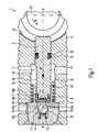
- FIGS. 1 to 6 a piston pump 1 according to a first embodiment of the present invention described.
- the piston pump 1 comprises a piston 3 arranged in a housing 2.
- the housing 2 has a stepped bore 2 a for receiving the piston 3.
- the piston 3 is driven by means disposed in an eccentric 21 eccentric 22 whose direction of rotation is indicated by the arrow D.
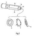
- the piston 3 is from the perspective view in FIG. 2 shown in detail. As can be seen, the piston 3 at its pressure-chamber-side end a stepped portion 3a and three along the circumference of the piston arranged flattened portions 3b. At the stepped portion 3a is, as in particular from the FIGS. 1 . 5 and 6 it can be seen, a sealing ring 4 is arranged.
- the sealing ring 4 is fixed to the stepped portion 3 a of the piston 3 by means of a spring element 7 and a plate-shaped retaining element 8.
- the plate-shaped holding element 8 is by means of an annular Attached mounting area in a recess 3d of the piston by means of a press fit.
- the piston pump 1 further comprises a pressure chamber 9, which is arranged between the sealing ring 4 and an outlet valve 11.
- a pressure chamber 9 which is arranged between the sealing ring 4 and an outlet valve 11.
- the return valve 11 comprises a ball 12 and a return spring 13.
- the return spring 13 is supported in a closure element 14, wherein the closure element 14 closes the stepped bore 2a of the housing 2 in a fluid-tight manner.
- the discharge valve 11 is followed by two pressure lines 15, to which the pressurized fluid from the pressure chamber 9 is supplied.
- the cylinder member 10 includes a plate-shaped base portion 10a having a flange-shaped cylinder ring 10b integrally formed thereon.
- the cylinder ring 10b has an inner peripheral surface 10c and an outer peripheral surface 10d.
- a central passage opening 10e is provided in the cylinder element 10, which is closed or released by means of the outlet valve 11.
- a return spring 16 is provided, which on the one hand is supported on the cylinder element 10 and on the other hand on a projecting portion 3c on the piston 3 (see. FIG. 1 ).
- supply lines 17 are further formed, which supply hydraulic fluid to a low pressure region 18.
- the return spring 16 for the piston 3 is also in the low pressure region 18 of Piston pump arranged.
- a sealing ring 19 and a guide ring 20 are further arranged in a groove-shaped recess in the piston on the piston 3.
- FIG. 3a shows a plan view of the sealing ring 4.
- the sealing ring 4 is formed as a closed ring and has at its inner periphery 4 projecting portions 5 and four recessed areas 6.
- the protruding areas 5 and the recessed areas 6 are each formed in a planar manner.
- FIG. 3b shows a sectional view of the sealing ring 4 along the line IV-IV. How out FIG. 3b can be seen, 5 relatively broad chamfers 5a on the low pressure side region of the sealing ring 4 and relatively wide chamfers 5b formed on the pressure chamber side portion of the sealing ring 4 at the projecting areas.
- the low-pressure side chamfers 5a allow a quick response of the sealing ring 4, if this is to take over the function of an inlet valve.
- the sealing ring 4 is arranged on the stepped portion 3a of the piston 3, that it is movable in the axial direction XX of the piston with a predetermined clearance S.
- the movement of the sealing ring 4 is limited on the one hand by the stepped portion 3a and on the other hand by the fixed to the piston 3 holding member 8, which has a diameter which is greater than the diameter of the stepped, pressure chamber side end of the piston 3.
- the spring element 7 is still arranged.
- the spring element 7 is in detail in the FIGS.
- the spring element 7 exerts a spring force in the axial direction XX on the sealing ring 4.
- the sealing ring 4 is preferably made of a plastic material, in particular of PA66 or PEEK or of a ceramic material.
- FIG. 5 shows the beginning of the suction phase of the piston pump, in which the piston 3 moves in the direction of arrow A.
- the sealing ring 4 is in the in FIG. 5 shown first position, so that hydraulic fluid, which is located in the low pressure region 18, the sealing ring 4 can flow over. This is in FIG. 5 indicated by the arrows.
- the exhaust valve 11 is in the closed position.
- the hydraulic fluid from the low-pressure region 18 flows over the sealing ring 4 at the inner circumference of the sealing ring 4 at the recessed areas 6 and passes through the spaces between the spring tongues 7b of the spring element 7 in the pressure chamber 9.
- the spring tongues 7b thus serve as a stop for the sealing ring. 4 , so that between the plate-shaped holding element 8 and the sealing ring 4, a gap remains free, through which the hydraulic fluid can flow into the pressure chamber 9.
- the spring element 7 exerts a spring force F F in the direction of movement A of the piston on the sealing element, but this spring force is smaller than that between the sealing ring 4 and the inner circumference 10c of the cylinder member 10 existing friction force F K , which acts against the spring force.
- the sealing ring 4 is during the intake of the piston pump in the in FIG. 5 shown position to suck hydraulic fluid.
- the sealing ring 4 allows that after the reversal of the direction of the piston 3 after reaching the bottom dead center, the connection between the pressure chamber 9 and the low-pressure region 18 is closed, since the sealing ring 4 both on the inner circumference 10c of the cylinder member 10 and the stepped portion 3a of the piston 3 seals. If the piston 3 moves further in the direction of arrow B, thus an ever-increasing pressure in the pressure chamber 9 is built up. Therefore, the exhaust valve 11 remains closed until the pressure in the pressure chamber 9 is greater than the pressure in the pressure lines 15. As soon as the pressure in the pressure chamber 9 exceeds the pressure in the pressure lines 15, the outlet valve 11 opens, so that the connection between the pressure chamber 9 and the pressure lines 15 is released via the passage opening 10e.
- the sealing ring 4 can fulfill both the sealing function during the pressure phase between the pressure chamber 9 and the rear pressure region 18 of the piston pump, and also fulfill the intake valve function during the intake phase of the piston pump. As a result, it is no longer necessary to provide a separate inlet valve for the pressure chamber 9, but a single component takes over both functions. The overflow of the sealing ring 4 in the suction takes place on the inner circumference. It should be noted that for a uniform pressure distribution on the sealing ring 4, the projecting portions 5 and the recessed portions 6 are preferably arranged symmetrically to the central axis of the sealing ring.
- the response of the seal ring 4 during the transition from the suction phase to the pressure phase and from the pressure phase to the suction phase respectively improved.
- the losses of the piston pump 1 can be reduced and an improved efficiency can be obtained.
- the inventive arrangement of the return spring 16 for the piston 3 outside the pressure chamber 9 allows the geometry of the pressure chamber 9 to be optimized can, since no return element for the piston must be arranged in the pressure chamber. In particular, this improved flow conditions in the pressure chamber 9 can be realized.
- the piston pump according to the invention is very easy to install, since on the one hand, the number of components could be reduced and on the other hand, for example, the sealing ring 4 with the spring element 7 and the support member 8 can be pre-assembled on the piston 3.
- the holding element 8 can be fastened by means of a press fit or by caulking in the recess 3d of the piston 3.
- FIG. 7 a piston pump 1 according to a second embodiment of the invention described. Identical or functionally identical parts are denoted by the same reference numerals as in the first embodiment.
- the piston pump 1 of the second embodiment substantially corresponds to that of the first embodiment, wherein instead of a cylindrical return spring 16 in the second embodiment, a tapered return spring 16 is used.
- the pressure-chamber-side end of the securely tapered return spring 16 is supported again on the cylinder element 10 and the The eccentric end of the tapered return spring 16 is supported on a circumferential groove 23, which is formed in the piston 3.
- the tapered return spring 16 of the second embodiment is particularly preferably wound directly on the piston 3, so that the assembly of the return spring 16 on the piston 3 can be automated.
- the piston pump 1 of FIG. 7 is shown in the pressure phase, the exhaust valve 11 is still closed and the pressure in the pressure chamber 9 with increasing movement of the piston 3 in the direction of its top dead center is constantly increasing.
- this embodiment corresponds to the first embodiment, so that reference may be made to the description given there.
- FIG. 8 shows a piston pump 1 according to a third embodiment of the present invention. Identical or functionally identical parts are again denoted by the same reference numerals as in the first embodiment.
- the sealing ring 4 is also formed as an inlet valve in the third embodiment.
- the piston pump 1 is in FIG. 8 thereby shown in their intake phase.
- a return spring for the piston 3 is formed in the third embodiment as a leaf spring 24, which is arranged in the eccentric chamber 21 of the piston pump 1.
- the Leaf spring 24 is attached to the eccentric end of the piston 3 in a groove 26 in the piston 3 and is supported against the wall of the eccentric 21 from.
- the arrangement of the return element in the eccentric 21 can continue to dispense with the cylinder member 10 of the previous embodiments. How out FIG. 8 it can be seen seals the sealing ring 4 directly against a portion of the stepped bore 2a in the housing 2 from. Instead of the cylinder element 10 in the previous embodiments, therefore, only one plate 25 for limiting the pressure chamber 9 must be arranged, which has a central passage opening 25a, which is closed or released by the outlet valve 11. Thus, the number of components of the piston pump 1 according to the third embodiment can be further reduced, so that in particular the manufacturing and assembly costs can be further reduced. Otherwise, the third embodiment corresponds to the previous embodiments, so that reference may be made to the description given there.
Applications Claiming Priority (2)
| Application Number | Priority Date | Filing Date | Title |
|---|---|---|---|
| DE200410037140 DE102004037140A1 (de) | 2004-07-30 | 2004-07-30 | Kolbenpumpe mit verbessertem Wirkungsgrad |
| PCT/EP2005/053377 WO2006013143A1 (de) | 2004-07-30 | 2005-07-14 | Kolbenpumpe mit verbessertem wirkungsgrad |
Publications (2)
| Publication Number | Publication Date |
|---|---|
| EP1774177A1 EP1774177A1 (de) | 2007-04-18 |
| EP1774177B1 true EP1774177B1 (de) | 2010-02-17 |
Family
ID=34972876
Family Applications (1)
| Application Number | Title | Priority Date | Filing Date |
|---|---|---|---|
| EP20050764040 Expired - Fee Related EP1774177B1 (de) | 2004-07-30 | 2005-07-14 | Kolbenpumpe mit verbessertem wirkungsgrad |
Country Status (7)
| Country | Link |
|---|---|
| US (1) | US20080310979A1 (ja) |
| EP (1) | EP1774177B1 (ja) |
| JP (1) | JP4651049B2 (ja) |
| KR (1) | KR101077506B1 (ja) |
| CN (1) | CN100460679C (ja) |
| DE (2) | DE102004037140A1 (ja) |
| WO (1) | WO2006013143A1 (ja) |
Families Citing this family (12)
| Publication number | Priority date | Publication date | Assignee | Title |
|---|---|---|---|---|
| DE102007049152A1 (de) * | 2007-10-12 | 2009-04-16 | Robert Bosch Gmbh | Hydraulische Kolbenpumpe |
| CN102575655A (zh) * | 2009-10-05 | 2012-07-11 | 舍弗勒技术股份两合公司 | 液压的泵装置 |
| DE102009047217A1 (de) * | 2009-11-27 | 2011-06-01 | Robert Bosch Gmbh | Kolbenplumpe |
| DE102010001237A1 (de) * | 2009-12-01 | 2011-06-09 | Continental Teves Ag & Co. Ohg | Kolbenpumpe |
| DE102009054520A1 (de) * | 2009-12-10 | 2011-06-16 | Robert Bosch Gmbh | Kolbenpumpe |
| DE102010040889A1 (de) * | 2010-09-16 | 2012-03-22 | Robert Bosch Gmbh | Pumpenaggregat |
| JP5579686B2 (ja) * | 2011-11-17 | 2014-08-27 | 日信工業株式会社 | プランジャポンプ |
| US9702350B2 (en) * | 2012-01-19 | 2017-07-11 | Ge Oil & Gas Compression Systems, Llc | Valveless reciprocating compressor |
| FI20125250L (fi) * | 2012-03-09 | 2013-09-10 | Waertsilae Finland Oy | Kaasunvaihtoventtiilijärjestely ja kaasunvaihtoventtiili |
| EP2746566A1 (en) * | 2012-12-18 | 2014-06-25 | Delphi International Operations Luxembourg S.à r.l. | Pump Unit |
| JP5915601B2 (ja) | 2013-07-24 | 2016-05-11 | 株式会社アドヴィックス | ピストンポンプ |
| KR102413429B1 (ko) | 2017-08-08 | 2022-06-28 | 주식회사 만도 | 브레이크 시스템용 피스톤 펌프 |
Family Cites Families (20)
| Publication number | Priority date | Publication date | Assignee | Title |
|---|---|---|---|---|
| US3224378A (en) * | 1964-01-09 | 1965-12-21 | George C Graham | Fluid pressure piston seal and valve |
| US3661479A (en) * | 1969-12-03 | 1972-05-09 | Kloeckner Humboldt Deutz Ag | Seal for reciprocating machine elements |
| JPS492561Y1 (ja) * | 1972-06-01 | 1974-01-22 | ||
| JPS539924Y2 (ja) * | 1972-06-13 | 1978-03-16 | ||
| JPS60114280U (ja) * | 1984-01-10 | 1985-08-02 | 株式会社 丸山製作所 | 強制弁式ピストンポンプ |
| CN85106444B (zh) * | 1985-08-27 | 1987-07-22 | 吉·豪谢尔的约胡姆股份有限公司豪欣科机器制造厂 | 径向活塞泵 |
| DE4140066A1 (de) * | 1991-12-05 | 1993-06-09 | Alfred Teves Gmbh, 6000 Frankfurt, De | Betaetigungseinheit fuer eine hydraulische bremsanlage |
| EP0631050B1 (en) * | 1993-06-25 | 1997-12-17 | Denso Corporation | Pump |
| JPH084650A (ja) * | 1994-06-16 | 1996-01-09 | Akebono Brake Ind Co Ltd | ポンプ |
| DE19503945A1 (de) * | 1995-02-07 | 1996-08-08 | Bosch Gmbh Robert | Federbelastetes Rückschlagventil |
| CN1155923A (zh) * | 1995-05-31 | 1997-07-30 | 罗伯特·博施有限公司 | 活塞泵 |
| ES2393276T3 (es) * | 1998-02-17 | 2012-12-20 | Nikkiso Company, Ltd. | Bomba de diafragma |
| US6220833B1 (en) * | 1999-01-06 | 2001-04-24 | Continental Teves, Inc. | Elimination of inlet valve for ABS pump |
| DE19918126B4 (de) * | 1999-04-22 | 2007-09-13 | Robert Bosch Gmbh | Kolbenpumpe |
| IT248789Y1 (it) * | 1999-11-30 | 2003-02-20 | Knorr Bremse Systeme | Pompa volumetrica alternativa, particolarmente per un gruppo dicomando servoassistito di un innesto a frizione per un autoveicolo |
| CN1161545C (zh) * | 2000-02-17 | 2004-08-11 | Lg电子株式会社 | 往复压缩机的吸气阀装置 |
| DE10013858A1 (de) * | 2000-03-21 | 2001-09-27 | Continental Teves Ag & Co Ohg | Kolbenpumpe mit Ventil-Montageeinheit |
| US6764286B2 (en) * | 2001-10-29 | 2004-07-20 | Kelsey-Hayes Company | Piston pump with pump inlet check valve |
| KR100491602B1 (ko) * | 2002-05-11 | 2005-05-27 | 삼성광주전자 주식회사 | 왕복동식 압축기의 이중 실린더장치 |
| US7104613B2 (en) * | 2004-07-28 | 2006-09-12 | Kelsey-Hayes Company | Pump with reciprocating high pressure seal and valve for vehicle braking systems |
-
2004
- 2004-07-30 DE DE200410037140 patent/DE102004037140A1/de not_active Withdrawn
-
2005
- 2005-07-14 EP EP20050764040 patent/EP1774177B1/de not_active Expired - Fee Related
- 2005-07-14 DE DE200550009044 patent/DE502005009044D1/de active Active
- 2005-07-14 WO PCT/EP2005/053377 patent/WO2006013143A1/de active Application Filing
- 2005-07-14 CN CNB2005800256407A patent/CN100460679C/zh not_active Expired - Fee Related
- 2005-07-14 KR KR1020077002391A patent/KR101077506B1/ko not_active IP Right Cessation
- 2005-07-14 JP JP2007523058A patent/JP4651049B2/ja not_active Expired - Fee Related
- 2005-07-14 US US11/658,267 patent/US20080310979A1/en not_active Abandoned
Also Published As
| Publication number | Publication date |
|---|---|
| US20080310979A1 (en) | 2008-12-18 |
| CN1993550A (zh) | 2007-07-04 |
| WO2006013143A1 (de) | 2006-02-09 |
| KR20070038535A (ko) | 2007-04-10 |
| JP4651049B2 (ja) | 2011-03-16 |
| DE102004037140A1 (de) | 2006-03-23 |
| CN100460679C (zh) | 2009-02-11 |
| DE502005009044D1 (ja) | 2010-04-01 |
| JP2008507661A (ja) | 2008-03-13 |
| EP1774177A1 (de) | 2007-04-18 |
| KR101077506B1 (ko) | 2011-10-28 |
Similar Documents
| Publication | Publication Date | Title |
|---|---|---|
| EP1774177B1 (de) | Kolbenpumpe mit verbessertem wirkungsgrad | |
| EP2336546B1 (de) | Kraftstoff-Hochdruckpumpe | |
| EP1774174B1 (de) | Kolbenpumpe mit kompakter haltevorrichtung für eine rückstellfeder | |
| DE19653895A1 (de) | Pumpe, insbesondere für eine hydraulische Bremsschlupfregelanlage | |
| WO2007147693A2 (de) | Kolbenpumpe | |
| EP1774176B1 (de) | Kolbenpumpe mit verbesserter druckaufbaudynamik | |
| EP0840856A1 (de) | Kolbenpumpe | |
| EP2519743B1 (de) | Kolbenpumpe mit einem einlassventil | |
| DE102010064114B4 (de) | Pumpe mit einer Drossel | |
| DE10129449A1 (de) | Kraftstoffhochdruckpumpe für Brennkraftmaschine mit verbessertem Teillastverhalten | |
| EP1319831B1 (de) | Kraftstoffhochdruckpumpe mit integrierter Sperrflügel-Vorförderpumpe | |
| EP3371430B1 (de) | Kühlmittelpumpe für eine verbrennungskraftmaschine | |
| DE102009047727A1 (de) | Kolbenpumpe mit einem Schließkörper am Einlassventil | |
| EP1759948B1 (de) | Kolbenpumpe | |
| EP0509077A1 (de) | Kolbenpumpe, insbesondere radialkolbenpumpe. | |
| WO2017198360A1 (de) | Kraftstoffhochdruckpumpe | |
| DE102004037145B4 (de) | Kolbenpumpe mit kompaktem Aufbau | |
| EP2212554B1 (de) | Radialkolbenpumpe | |
| WO2002012728A1 (de) | Axialschubausgleichseinrichtung | |
| WO2003078840A1 (de) | Spülventil | |
| DE102013215953A1 (de) | Hochdruckpumpe | |
| DE102004027511A1 (de) | Leckagefreie Kolbenpumpe | |
| EP1454061A1 (de) | Flügelzellenpumpe | |
| DE102007008766A1 (de) | Pumpeinrichtung |
Legal Events
| Date | Code | Title | Description |
|---|---|---|---|
| PUAI | Public reference made under article 153(3) epc to a published international application that has entered the european phase |
Free format text: ORIGINAL CODE: 0009012 |
|
| 17P | Request for examination filed |
Effective date: 20070228 |
|
| AK | Designated contracting states |
Kind code of ref document: A1 Designated state(s): DE FR GB IT |
|
| DAX | Request for extension of the european patent (deleted) | ||
| RBV | Designated contracting states (corrected) |
Designated state(s): DE FR GB IT |
|
| 17Q | First examination report despatched |
Effective date: 20071213 |
|
| GRAP | Despatch of communication of intention to grant a patent |
Free format text: ORIGINAL CODE: EPIDOSNIGR1 |
|
| GRAC | Information related to communication of intention to grant a patent modified |
Free format text: ORIGINAL CODE: EPIDOSCIGR1 |
|
| GRAS | Grant fee paid |
Free format text: ORIGINAL CODE: EPIDOSNIGR3 |
|
| GRAA | (expected) grant |
Free format text: ORIGINAL CODE: 0009210 |
|
| AK | Designated contracting states |
Kind code of ref document: B1 Designated state(s): DE FR GB IT |
|
| REG | Reference to a national code |
Ref country code: GB Ref legal event code: FG4D Free format text: NOT ENGLISH |
|
| REF | Corresponds to: |
Ref document number: 502005009044 Country of ref document: DE Date of ref document: 20100401 Kind code of ref document: P |
|
| PLBE | No opposition filed within time limit |
Free format text: ORIGINAL CODE: 0009261 |
|
| STAA | Information on the status of an ep patent application or granted ep patent |
Free format text: STATUS: NO OPPOSITION FILED WITHIN TIME LIMIT |
|
| 26N | No opposition filed |
Effective date: 20101118 |
|
| PG25 | Lapsed in a contracting state [announced via postgrant information from national office to epo] |
Ref country code: IT Free format text: LAPSE BECAUSE OF FAILURE TO SUBMIT A TRANSLATION OF THE DESCRIPTION OR TO PAY THE FEE WITHIN THE PRESCRIBED TIME-LIMIT Effective date: 20100217 |
|
| PGFP | Annual fee paid to national office [announced via postgrant information from national office to epo] |
Ref country code: GB Payment date: 20130723 Year of fee payment: 9 Ref country code: FR Payment date: 20130719 Year of fee payment: 9 |
|
| GBPC | Gb: european patent ceased through non-payment of renewal fee |
Effective date: 20140714 |
|
| REG | Reference to a national code |
Ref country code: FR Ref legal event code: ST Effective date: 20150331 |
|
| PG25 | Lapsed in a contracting state [announced via postgrant information from national office to epo] |
Ref country code: GB Free format text: LAPSE BECAUSE OF NON-PAYMENT OF DUE FEES Effective date: 20140714 Ref country code: FR Free format text: LAPSE BECAUSE OF NON-PAYMENT OF DUE FEES Effective date: 20140731 |
|
| REG | Reference to a national code |
Ref country code: DE Ref legal event code: R084 Ref document number: 502005009044 Country of ref document: DE |
|
| PGFP | Annual fee paid to national office [announced via postgrant information from national office to epo] |
Ref country code: DE Payment date: 20200924 Year of fee payment: 16 |
|
| REG | Reference to a national code |
Ref country code: DE Ref legal event code: R119 Ref document number: 502005009044 Country of ref document: DE |
|
| PG25 | Lapsed in a contracting state [announced via postgrant information from national office to epo] |
Ref country code: DE Free format text: LAPSE BECAUSE OF NON-PAYMENT OF DUE FEES Effective date: 20220201 |