EP1772947A2 - Antrieb für ein Mobilfahrzeug - Google Patents
Antrieb für ein Mobilfahrzeug Download PDFInfo
- Publication number
- EP1772947A2 EP1772947A2 EP06019119A EP06019119A EP1772947A2 EP 1772947 A2 EP1772947 A2 EP 1772947A2 EP 06019119 A EP06019119 A EP 06019119A EP 06019119 A EP06019119 A EP 06019119A EP 1772947 A2 EP1772947 A2 EP 1772947A2
- Authority
- EP
- European Patent Office
- Prior art keywords
- spur gear
- drive
- sensor
- mobile vehicle
- speed
- Prior art date
- Legal status (The legal status is an assumption and is not a legal conclusion. Google has not performed a legal analysis and makes no representation as to the accuracy of the status listed.)
- Granted
Links
- 230000001419 dependent effect Effects 0.000 claims 1
- 230000007547 defect Effects 0.000 description 3
- 230000006698 induction Effects 0.000 description 2
- 230000005540 biological transmission Effects 0.000 description 1
- 238000001514 detection method Methods 0.000 description 1
Images

Classifications
-
- H—ELECTRICITY
- H02—GENERATION; CONVERSION OR DISTRIBUTION OF ELECTRIC POWER
- H02K—DYNAMO-ELECTRIC MACHINES
- H02K7/00—Arrangements for handling mechanical energy structurally associated with dynamo-electric machines, e.g. structural association with mechanical driving motors or auxiliary dynamo-electric machines
- H02K7/10—Structural association with clutches, brakes, gears, pulleys or mechanical starters
- H02K7/116—Structural association with clutches, brakes, gears, pulleys or mechanical starters with gears
-
- B—PERFORMING OPERATIONS; TRANSPORTING
- B60—VEHICLES IN GENERAL
- B60K—ARRANGEMENT OR MOUNTING OF PROPULSION UNITS OR OF TRANSMISSIONS IN VEHICLES; ARRANGEMENT OR MOUNTING OF PLURAL DIVERSE PRIME-MOVERS IN VEHICLES; AUXILIARY DRIVES FOR VEHICLES; INSTRUMENTATION OR DASHBOARDS FOR VEHICLES; ARRANGEMENTS IN CONNECTION WITH COOLING, AIR INTAKE, GAS EXHAUST OR FUEL SUPPLY OF PROPULSION UNITS IN VEHICLES
- B60K7/00—Disposition of motor in, or adjacent to, traction wheel
- B60K7/0007—Disposition of motor in, or adjacent to, traction wheel the motor being electric
-
- B—PERFORMING OPERATIONS; TRANSPORTING
- B60—VEHICLES IN GENERAL
- B60L—PROPULSION OF ELECTRICALLY-PROPELLED VEHICLES; SUPPLYING ELECTRIC POWER FOR AUXILIARY EQUIPMENT OF ELECTRICALLY-PROPELLED VEHICLES; ELECTRODYNAMIC BRAKE SYSTEMS FOR VEHICLES IN GENERAL; MAGNETIC SUSPENSION OR LEVITATION FOR VEHICLES; MONITORING OPERATING VARIABLES OF ELECTRICALLY-PROPELLED VEHICLES; ELECTRIC SAFETY DEVICES FOR ELECTRICALLY-PROPELLED VEHICLES
- B60L3/00—Electric devices on electrically-propelled vehicles for safety purposes; Monitoring operating variables, e.g. speed, deceleration or energy consumption
- B60L3/0023—Detecting, eliminating, remedying or compensating for drive train abnormalities, e.g. failures within the drive train
- B60L3/0038—Detecting, eliminating, remedying or compensating for drive train abnormalities, e.g. failures within the drive train relating to sensors
-
- H—ELECTRICITY
- H02—GENERATION; CONVERSION OR DISTRIBUTION OF ELECTRIC POWER
- H02K—DYNAMO-ELECTRIC MACHINES
- H02K11/00—Structural association of dynamo-electric machines with electric components or with devices for shielding, monitoring or protection
- H02K11/20—Structural association of dynamo-electric machines with electric components or with devices for shielding, monitoring or protection for measuring, monitoring, testing, protecting or switching
- H02K11/21—Devices for sensing speed or position, or actuated thereby
-
- B—PERFORMING OPERATIONS; TRANSPORTING
- B60—VEHICLES IN GENERAL
- B60K—ARRANGEMENT OR MOUNTING OF PROPULSION UNITS OR OF TRANSMISSIONS IN VEHICLES; ARRANGEMENT OR MOUNTING OF PLURAL DIVERSE PRIME-MOVERS IN VEHICLES; AUXILIARY DRIVES FOR VEHICLES; INSTRUMENTATION OR DASHBOARDS FOR VEHICLES; ARRANGEMENTS IN CONNECTION WITH COOLING, AIR INTAKE, GAS EXHAUST OR FUEL SUPPLY OF PROPULSION UNITS IN VEHICLES
- B60K17/00—Arrangement or mounting of transmissions in vehicles
- B60K17/04—Arrangement or mounting of transmissions in vehicles characterised by arrangement, location or kind of gearing
- B60K17/043—Transmission unit disposed in on near the vehicle wheel, or between the differential gear unit and the wheel
- B60K17/046—Transmission unit disposed in on near the vehicle wheel, or between the differential gear unit and the wheel with planetary gearing having orbital motion
-
- B—PERFORMING OPERATIONS; TRANSPORTING
- B60—VEHICLES IN GENERAL
- B60K—ARRANGEMENT OR MOUNTING OF PROPULSION UNITS OR OF TRANSMISSIONS IN VEHICLES; ARRANGEMENT OR MOUNTING OF PLURAL DIVERSE PRIME-MOVERS IN VEHICLES; AUXILIARY DRIVES FOR VEHICLES; INSTRUMENTATION OR DASHBOARDS FOR VEHICLES; ARRANGEMENTS IN CONNECTION WITH COOLING, AIR INTAKE, GAS EXHAUST OR FUEL SUPPLY OF PROPULSION UNITS IN VEHICLES
- B60K7/00—Disposition of motor in, or adjacent to, traction wheel
- B60K2007/0038—Disposition of motor in, or adjacent to, traction wheel the motor moving together with the wheel axle
-
- B—PERFORMING OPERATIONS; TRANSPORTING
- B60—VEHICLES IN GENERAL
- B60K—ARRANGEMENT OR MOUNTING OF PROPULSION UNITS OR OF TRANSMISSIONS IN VEHICLES; ARRANGEMENT OR MOUNTING OF PLURAL DIVERSE PRIME-MOVERS IN VEHICLES; AUXILIARY DRIVES FOR VEHICLES; INSTRUMENTATION OR DASHBOARDS FOR VEHICLES; ARRANGEMENTS IN CONNECTION WITH COOLING, AIR INTAKE, GAS EXHAUST OR FUEL SUPPLY OF PROPULSION UNITS IN VEHICLES
- B60K7/00—Disposition of motor in, or adjacent to, traction wheel
- B60K2007/0061—Disposition of motor in, or adjacent to, traction wheel the motor axle being parallel to the wheel axle
-
- B—PERFORMING OPERATIONS; TRANSPORTING
- B60—VEHICLES IN GENERAL
- B60L—PROPULSION OF ELECTRICALLY-PROPELLED VEHICLES; SUPPLYING ELECTRIC POWER FOR AUXILIARY EQUIPMENT OF ELECTRICALLY-PROPELLED VEHICLES; ELECTRODYNAMIC BRAKE SYSTEMS FOR VEHICLES IN GENERAL; MAGNETIC SUSPENSION OR LEVITATION FOR VEHICLES; MONITORING OPERATING VARIABLES OF ELECTRICALLY-PROPELLED VEHICLES; ELECTRIC SAFETY DEVICES FOR ELECTRICALLY-PROPELLED VEHICLES
- B60L2220/00—Electrical machine types; Structures or applications thereof
- B60L2220/40—Electrical machine applications
- B60L2220/46—Wheel motors, i.e. motor connected to only one wheel
-
- B—PERFORMING OPERATIONS; TRANSPORTING
- B60—VEHICLES IN GENERAL
- B60L—PROPULSION OF ELECTRICALLY-PROPELLED VEHICLES; SUPPLYING ELECTRIC POWER FOR AUXILIARY EQUIPMENT OF ELECTRICALLY-PROPELLED VEHICLES; ELECTRODYNAMIC BRAKE SYSTEMS FOR VEHICLES IN GENERAL; MAGNETIC SUSPENSION OR LEVITATION FOR VEHICLES; MONITORING OPERATING VARIABLES OF ELECTRICALLY-PROPELLED VEHICLES; ELECTRIC SAFETY DEVICES FOR ELECTRICALLY-PROPELLED VEHICLES
- B60L2240/00—Control parameters of input or output; Target parameters
- B60L2240/40—Drive Train control parameters
- B60L2240/42—Drive Train control parameters related to electric machines
- B60L2240/421—Speed
-
- Y—GENERAL TAGGING OF NEW TECHNOLOGICAL DEVELOPMENTS; GENERAL TAGGING OF CROSS-SECTIONAL TECHNOLOGIES SPANNING OVER SEVERAL SECTIONS OF THE IPC; TECHNICAL SUBJECTS COVERED BY FORMER USPC CROSS-REFERENCE ART COLLECTIONS [XRACs] AND DIGESTS
- Y02—TECHNOLOGIES OR APPLICATIONS FOR MITIGATION OR ADAPTATION AGAINST CLIMATE CHANGE
- Y02T—CLIMATE CHANGE MITIGATION TECHNOLOGIES RELATED TO TRANSPORTATION
- Y02T10/00—Road transport of goods or passengers
- Y02T10/60—Other road transportation technologies with climate change mitigation effect
- Y02T10/64—Electric machine technologies in electromobility
Definitions
- the invention relates to a drive for a mobile vehicle according to the closer defined in the preamble of claim 1.
- Generic drives consist of an electric motor, which drives a drive wheel via at least one reduction gear, wherein the rotational speed of the electric drive machine is often used as an input variable of a speed control.
- Electric induction machines a precise knowledge of the rotor speed is necessary to allow a sensitive control.
- sensor bearings which output the speed of the rotor, which in case of failure of this sensor bearing the complete drive must be dismantled.
- the DE 40 10 742 C1 discloses a generic drive of a truck, in which an electric motor via a spur gear and a planetary gear drives a drive wheel, and the drive wheel is braked via a brake.
- the present invention has for its object to provide a drive for a mobile vehicle, in particular an industrial truck, in which an electric motor drives a drive gear via a reduction gear, the drive has a sensitive speed control, and thus speed control, and the drive, in particular Its overall length is compact.
- the object is achieved with a, the characterizing features of the main claim, generic drive for a mobile vehicle.
- the drive has an electric drive motor which drives a vehicle wheel via at least one reduction gear, wherein the axis of rotation of the drive motor is arranged at a distance from the axis of rotation of the vehicle wheel.
- the drive has a rotational speed sensor which penetrates the housing of the drive and is operatively connected to a rotating component of the drive in such a way that the sensor outputs the rotational speed of the drive motor shaft or of a component which is in constant speed ratio therewith. Since the speed sensor penetrates the housing in which the reduction gear is arranged, it can be easily replaced in case of a defect without having to disassemble the drive. Especially with industrial trucks, it is necessary to leave the drive installed in the vehicle and still be able to replace the speed sensor.
- the speed sensor is therefore either in the region of the extension of the axis of rotation of the drive shaft of the electric motor, based on the drive pinion, arranged on the opposite side of the electric motor or radially on the circumference of the driven spur gear of a spur gear, wherein the drive shaft of the electric motor drives the first spur gear. This makes it possible to replace the speed sensors even when installed in the vehicle drive.
- the drive motor shaft drives a first spur gear on whose axial surface, which is located on the side facing away from the drive motor, a di-pole is arranged, which is in operative connection with a sine-cosine position sensor, which in the extension of the axis of rotation of the drive motor is arranged.
- This sensor outputs speed signals that directly reflect the speed of the drive motor shaft. With incremental speed detection, at least 64 pulses per rotor revolution are output. Often the number of impulses is higher.
- the sine cosine position sensor detects the "position", So the current angular position of the rotor. A speed is generated from the position.
- the drive motor drives a first spur gear of a reduction gear stage, which drives a further spur gear whose teeth are in operative connection with a speed sensor.
- This speed sensor is arranged either in the axial region or in the radial region on the circumference of the further spur gear adjacent to the toothing in order to output pulses which reflect the rotational speed of the further spur gear.
- An electronic control unit determines, based on the reduction gear ratio of the first and second spur gear and the pulses of the sensor, the rotational speed of the electric motor shaft.
- the shaft of the electric drive motor drives a first spur gear, which drives a further spur gear.
- An encoder wheel is rotatably connected to the further spur gear and is in operative connection with an axially arranged thereon speed sensor.
- the speed sensors which are in operative connection with the further spur gear or the encoder wheel, penetrate the gearbox housing and can partially protrude from the gearbox housing. This makes it possible, in the event of a defect of the sensor to dismantle this in a simple manner. If the sensor is arranged in the area of the footprint of the vehicle wheel, it is possible to design the transmission housing in such a way that the speed sensor is protected against damage. For this purpose, it is possible to arrange Gußrippen in the range of the speed sensor.
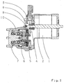
- An electric drive motor 1 drives with its shaft 2 a first spur gear 3 of a spur gear 4.
- the first spur gear 3 drives a further spur gear 5, which drives a hub 7 via a planetary gear 6, which drives a drive wheel (not shown).
- a di-pole 8 is in operative connection with the first spur gear 3 or is connected to it in a torque-proof manner.
- the di-pole 8 rotates and the sine-cosine position sensor 9 outputs signals as a function of the rotational speed of the shaft 2.
- the sine-cosine position sensor 9 penetrates the housing 10 and is arranged on the side facing away from the electric drive motor 1 side of the housing 10.
- the sine-cosine position sensor 9 protrudes partially out of the housing 10, which allows an exchange of the sensor 9.
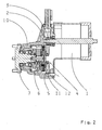
- An electric drive motor 1 drives with its shaft 2 a first spur gear 3 of a spur gear 4.
- the first spur gear 3 drives a further spur gear 5, which drives the hub 7 via a planetary gear 6.
- a speed sensor 11 is arranged, which in the region of the toothing 12, upon rotation of the further spur gear 5, outputs speed pulses.
- the rotational speed sensor 11 penetrates the housing 10 and is arranged radially to the further spur gear 5. A portion of the speed sensor 11 protrudes from the housing 10, whereby a disassembly of the sensor 1 is made possible.
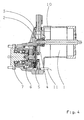
- An electric drive motor 1 drives via its shaft 2, a first spur gear 3 and this another spur gear 5 at.
- a donor wheel 12 is rotatably connected to the further spur gear 5.
- a speed sensor 11 is arranged axially adjacent to the encoder wheel 12 and outputs depending on the speed of the further spur gear 5 speed pulses.
- the rotational speed sensor 11 penetrates the housing 10 and is arranged at a distance from the rotational axis 13 and the rotational axis 14. It is possible, the housing 10 in such a way that housing ribs protect the speed sensor 11 from damage.
- An electric drive motor 11 drives via its shaft 2 a first spur gear 3 and this another spur gear 5 at. Adjacent to the toothing of the further spur gear 5, a rotational speed sensor 11 is axially arranged, which penetrates the housing 10 and thus can be exchanged in a simple manner in the event of a defect.
Landscapes
- Engineering & Computer Science (AREA)
- Power Engineering (AREA)
- Transportation (AREA)
- Mechanical Engineering (AREA)
- Chemical & Material Sciences (AREA)
- Combustion & Propulsion (AREA)
- Microelectronics & Electronic Packaging (AREA)
- Life Sciences & Earth Sciences (AREA)
- Sustainable Development (AREA)
- Sustainable Energy (AREA)
- Arrangement Or Mounting Of Propulsion Units For Vehicles (AREA)
- Connection Of Motors, Electrical Generators, Mechanical Devices, And The Like (AREA)
- Electric Propulsion And Braking For Vehicles (AREA)
Abstract
Description
- Die Erfindung betrifft einen Antrieb für ein Mobilfahrzeug nach der im Oberbegriff von Anspruch 1 näher definierten Art.
- Gattungsgemäße Antriebe bestehen aus einem Elektromotor, welcher über mindestens ein Untersetzungsgetriebe ein Antriebsrad antreibt, wobei die Drehzahl der elektrischen Antriebsmaschine häufig als Eingangsgröße einer Geschwindigkeitsregelung verwendet wird. Bei elektrischen Drehfeldmaschinen ist eine genaue Kenntnis der Rotorgeschwindigkeit notwendig, um eine feinfühlige Regelung zu ermöglichen. Häufig werden bei Drehfeldmaschinen Sensorlager verwendet, weiche die Drehzahl des Rotors ausgeben, wobei bei einem Defekt dieses Sensorlagers der komplette Antrieb demontiert werden muß.
- Die
DE 40 10 742 C1 offenbart einen gattungsgemäßen Antrieb eines Flurförderzeuges, bei welchem ein Elektromotor über ein Stirnradgetriebe und ein Planetengetriebe ein Antriebsrad antreibt, und das Antriebsrad über eine Bremse bremsbar ist. - Der vorliegenden Erfindung liegt die Aufgabe zugrunde, einen Antrieb für ein Mobilfahrzeug, insbesondere ein Flurförderzeug, zu schaffen, bei welchem ein Elektromotor über ein Untersetzungsgetriebe ein Antriebsrad antreibt, der Antrieb eine feinfühlige Drehzahlregelung, und somit Geschwindigkeitsregelung, aufweist, und der Antrieb, insbesondere in seiner Baulänge, kompakt ausgeführt ist.
- Die Aufgabe wird mit einem, auch die kennzeichnenden Merkmale des Hauptanspruchs aufweisenden, gattungsgemäßen Antrieb für ein Mobilfahrzeug gelöst.
- Erfindungsgemäß weist der Antrieb einen elektrischen Antriebsmotor auf, welcher über mindestens ein Untersetzungsgetriebe ein Fahrzeugrad antreibt, wobei die Drehachse des Antriebsmotors beabstandet zur Drehachse des Fahrzeugrades angeordnet ist. Der Antrieb weist einen Drehzahlsensor auf, welcher das Gehäuse des Antriebs durchdringt und mit einem drehenden Bauteil des Antriebs so in Wirkverbindung steht, dass der Sensor die Drehzahl der Antriebsmotorwelle oder eines mit dieser in konstantem Drehzahlverhältnis stehenden Bauteils ausgibt. Da der Drehzahlsensor das Gehäuse, in welchem das Untersetzungsgetriebe angeordnet ist, durchdringt, kann er auf einfache Weise bei einem Defekt ausgetauscht werden, ohne den Antrieb demontieren zu müssen. Insbesondere bei Flurförderzeugen ist es notwendig, den Antrieb eingebaut im Fahrzeug zu belassen und dennoch den Drehzahlsensor austauschen zu können. Der Drehzahlsensor ist deshalb entweder im Bereich der Verlängerung der Drehachse der Antriebswelle des Elektromotors, bezogen auf das Antriebsritzel, auf der gegenüberliegenden Seite des Elektromotors oder im radial am Umfang des abtreibenden Stirnrades eines Stirnradgetriebes angeordnet, wobei die Antriebswelle des Elektromotors das este Stirnrad antreibt. Dadurch besteht die Möglichkeit, den Drehzahlsensoren auch bei im Fahrzeug eingebauten Antrieb austauschen zu können.
- In einer weiteren Ausgestaltungsform der Erfindung treibt die Antriebsmotorwelle ein erstes Stirnrad an, an dessen axialer Fläche, welche sich an der dem Antriebsmotor abgewandten Seite befindet, ein Di-Pol angeordnet ist, welcher mit einem Sinus-Cosinus-Lagesensor in Wirkverbindung steht, welcher in der Verlängerung der Drehachse des Antriebsmotors angeordnet ist. Dieser Sensor gibt Drehzahlsignale aus, welche direkt die Drehzahl der Antriebsmotorwelle wiedergeben. Bei einer inkrementellen Drehzahlerfassung werden mindestens 64 Impulse pro Rotorumdrehung ausgegeben. Häufig liegt die Anzahl der Impulse höher. Der Sinus-Cosinus-Lagesensor erfaßt die "Lage", also die aktuelle Winkelstellung des Rotors. Eine Drehzahl wird aus der Lage generiert.
- Bei einer weiteren Ausgestaltungsform der Erfindung treibt der Antriebsmotor ein erstes Stirnrad einer Untersetzungsgetriebestufe an, welches ein weiteres Stirnrad antreibt, dessen Verzahnung mit einem Drehzahlsensor in Wirkverbindung steht. Dieser Drehzahlsensor ist entweder im axialen Bereich oder im radialen Bereich am Umfang des weiteren Stirnrades benachbart zur Verzahnung angeordnet, um Impulse, welche die Drehzahl des weiteren Stirnrades widerspiegeln, auszugeben. Eine elektronische Steuereinheit ermittelt, ausgehend vom Untersetzungsgetriebeverhältnis des ersten und zweiten Stirnrades sowie den Impulsen des Sensors, die Drehzahl der Elektromotorwelle.
- In einer weiteren Ausgestaltungsform der Erfindung treibt die Welle des elektrischen Antriebsmotors ein erstes Stirnrad an, welches ein weiteres Stirnrad antreibt. Ein Geberrad ist drehfest mit dem weiteren Stirnrad verbunden und steht in Wirkverbindung mit einem axial zu diesem angeordneten Drehzahlsensor. Die Drehzahlsensoren, welche mit dem weiteren Stirnrad oder dem Geberrad in Wirkverbindung stehen, durchdringen das Getriebegehäuse und können teilweise aus dem Getriebegehäuse ragen. Hierdurch besteht die Möglichkeit, bei einem Defekt des Sensors diesen auf einfache Weise zu demontieren. Ist der Sensor im Bereich der Aufstandsfläche des Fahrzeugrades angeordnet, so besteht die Möglichkeit, das Getriebegehäuse so auszubilden, dass der Drehzahlsensor vor Beschädigungen geschützt ist. Hierzu besteht die Möglichkeit, Gußrippen im Bereich des Drehzahlsensors anzuordnen.
- Weitere Merkmale sind der Figuren-Beschreibung zu entnehmen.
- Es zeigen:
- Fig. 1
- einen Antrieb mit einem Di-Pol und Sinus-Cosinus-Lagesensor;
- Fig. 2
- einen Antrieb mit einem radial zum weiteren Stirnrad angeordneten Drehzahlsensor;
- Fig. 3
- einen Antrieb mit dem weiteren Stirnrad verbundenen Geberrad und einem Drehzahlsensor und
- Fig. 4
- einen axial zum weiteren Stirnrad angeordneten Drehzahlsensor.
- Ein elektrischer Antriebsmotor 1 treibt mit seiner Welle 2 ein erstes Stirnrad 3 eines Stirnradgetriebes 4 an. Das erste Stirnrad 3 treibt ein weiteres Stirnrad 5 an, welches über ein Planetengetriebe 6 eine Nabe 7 antreibt, welche ein nicht gezeigtes Antriebsrad antreibt. Ein Di-Pol 8 steht mit dem ersten Stirnrad 3 in Wirkverbindung bzw. ist mit diesem drehfest verbunden. Bei Drehung der Welle 2 dreht sich der Di-Pol 8 und der Sinus-Cosinus-Lagesensor 9 gibt Signale in Abhängigkeit der Drehzahl der Welle 2 aus. Der Sinus-Cosinus-Lagesensor 9 durchdringt das Gehäuse 10 und ist auf der dem elektrischen Antriebsmotor 1 abgewandten Seite des Gehäuses 10 angeordnet. Der Sinus-Cosinus-Lagesensor 9 ragt teilweise aus dem Gehäuse 10 heraus, welches einen Austausch des Sensors 9 ermöglicht.
- Ein elektrischer Antriebsmotor 1 treibt mit seiner Welle 2 ein erstes Stirnrad 3 eines Stirnradgetriebes 4 an. Das erste Stirnrad 3 treibt ein weiteres Stirnrad 5 an, welches über ein Planetengetriebe 6 die Nabe 7 antreibt. Am radialen Umfang des weiteren Stirnrades 5 ist ein Drehzahlsensor 11 angeordnet, welcher im Bereich der Verzahnung 12, bei Drehung des weiteren Stirnrades 5, Drehzahlimpulse ausgibt. Der Drehzahlsensor 11 durchdringt das Gehäuse 10 und ist radial zum weiteren Stirnrad 5 angeordnet. Ein Teil des Drehzahlsensors 11 ragt aus dem Gehäuse 10, wodurch eine Demontage des Sensors 1 ermöglicht wird.
- Ein elektrischer Antriebsmotor 1 treibt über seine Welle 2 ein erstes Stirnrad 3 und dieses ein weiteres Stirnrad 5 an. Ein Geberrad 12 ist drehfest mit dem weiteren Stirnrad 5 verbunden. Ein Drehzahlsensor 11 ist axial benachbart zum Geberrad 12 angeordnet und gibt in Abhängigkeit der Drehzahl des weiteren Stirnrades 5 Drehzahlimpulse aus. Der Drehzahlsensor 11 durchdringt das Gehäuse 10 und ist beabstandet zur Drehachse 13 und Drehachse 14 angeordnet. Es besteht die Möglichkeit, das Gehäuse 10 so auszubilden, dass Gehäuserippen den Drehzahlsensor 11 vor Beschädigung schützen.
- Ein elektrischer Antriebsmotor 11 treibt über seine Welle 2 ein erstes Stirnrad 3 und dieses ein weiteres Stirnrad 5 an. Benachbart zur Verzahnung des weiteren Stirnrades 5 ist axial ein Drehzahlsensor 11 angeordnet, welcher das Gehäuse 10 durchdringt und somit auf einfache Art bei einem Defekt ausgetauscht werden kann.
-
- 1
- elektrischer Antriebsmotor
- 2
- Welle
- 3
- erstes Stirnrad
- 4
- Stirnradgetriebe
- 5
- weiteres Stirnrad
- 6
- Planetengetriebe
- 7
- Nabe
- 8
- Di-Pol
- 9
- Sinus-Cosinus-Lagesensor
- 10
- Gehäuse
- 11
- Drehzahlsensor
- 12.
- Geberrad
- 13
- Drehachse
- 14
- Drehachse
Claims (10)
- Antrieb für ein Mobilfahrzeug mit einem elektrischen Antriebsmotor (1), welcher über mindestens ein Untersetzungsgetriebe (4) ein Fahrzeugrad antreibt, wobei die Drehachse (13) des Antriebsmotors (1) beabstandet zur Drehachse (14) des Fahrzeugrades angeordnet ist, dadurch gekennzeichnet, dass drehende Bauteile (3, 5) des Untersetzungsgetriebes mit einem Drehzahlsensor (11) in Wirkverbindung stehen, so dass der Drehzahlsensor (11) Drehzahlsignale ausgibt, welche in Abhängigkeit der Drehzahl des Antriebsmotors (1) stehen, wobei der Drehzahlsensor (11) ohne eine Demontage des Antriebs austauschbar ist.
- Antrieb für ein Mobilfahrzeug nach Anspruch 1, dadurch gekennzeichnet, dass der Antriebsmotor (1) ein Stirnrad (3) antreibt, welches mit einem magnetischen Di-Pol (8) an seiner dem Antriebsmotor (1) abgewandten axialen Fläche verbunden ist, wobei der Di-Pol (8) mit einem Sinus-Cosinus-Lagesensor (9) in Wirkverbindung steht.
- Antrieb für ein Mobilfahrzeug nach Anspruch 2, dadurch gekennzeichnet, dass der Lagesensor (9) in dem Getriebegehäuse (10) im Bereich des Stirnrades (3) angeordnet ist.
- Antrieb für ein Mobilfahrzeug nach Anspruch 1, dadurch gekennzeichnet, dass der Drehzahlsensor (11) teilweise aus dem Untersetzungsgetriebegehäuse (10) ragt.
- Antrieb für ein Mobilfahrzeug nach Anspruch 4, dadurch gekennzeichnet, dass der aus dem Untersetzungsgetriebegehäuse (10) ragende Teil des Sensors (11), zumindest in Richtung Fahrzeugradaufstandsfläche, durch Gußrippen des Untersetzungsgetriebegehäuses (10) geschützt ist.
- Antrieb für ein Mobilfahrzeug nach Anspruch 1, dadurch gekennzeichnet, dass der Antriebsmotor (1) ein Stirnrad (3) antreibt, welches mit einem weiteren Stirnrad (5) in Wirkverbindung steht, wobei der Drehzahlsensor (11) im Bereich der Verzahnung des weiteren Stirnrades (5) angeordnet ist und so mit dieser Verzahnung zusammenwirkt, dass er Drehzahlsignale der Drehzahl des weiteren Stirnrades (5) ausgibt.
- Antrieb für ein Mobilfahrzeug nach Anspruch 6, dadurch gekennzeichnet, dass der Sensor (11) radial am Umfang des weiteren Stirnrades (5) angeordnet ist.
- Antrieb für ein Mobilfahrzeug nach Anspruch 6, dadurch gekennzeichnet, dass der Sensor (111) axial im Bereich der Verzahnung des weiteren Stirnrades (5) angeordnet ist.
- Antrieb für ein Mobilfahrzeug nach Anspruch 1, dadurch gekenn- zeichnet, dass der Antriebsmotor (1) ein Stirnrad (3) antreibt, welches mit einem weiteren Stirnrad (5) in Wirkverbindung steht, wobei das weitere Stirnrad (5) drehfest mit einem koaxial zum weiteren Stirnrad (5) angeordneten Geberrad (12) verbunden ist, und ein Drehzahlsensor (11) im Bereich des Geberrades (12) angeordnet ist und so mit diesem Geberrad (12) zusammenwirkt, dass er Drehahlsignale der Drehzahl des weiteren Stirnrades (5) ausgibt.
- Antrieb für ein Mobilfahrzeug nach Anspruch 9, dadurch gekennzeichnet, dass der mit dem Geberrad (12) zusammenwirkende Drehzahlsensor (11) parallel zur Drehachse (14) des Geberrades (12) angeordnet ist.
Applications Claiming Priority (1)
| Application Number | Priority Date | Filing Date | Title |
|---|---|---|---|
| DE102005047953A DE102005047953A1 (de) | 2005-10-06 | 2005-10-06 | Antrieb für ein Mobilfahrzeug |
Publications (3)
| Publication Number | Publication Date |
|---|---|
| EP1772947A2 true EP1772947A2 (de) | 2007-04-11 |
| EP1772947A3 EP1772947A3 (de) | 2010-05-05 |
| EP1772947B1 EP1772947B1 (de) | 2013-11-06 |
Family
ID=37028814
Family Applications (1)
| Application Number | Title | Priority Date | Filing Date |
|---|---|---|---|
| EP06019119.4A Not-in-force EP1772947B1 (de) | 2005-10-06 | 2006-09-13 | Antrieb für ein Mobilfahrzeug |
Country Status (2)
| Country | Link |
|---|---|
| EP (1) | EP1772947B1 (de) |
| DE (1) | DE102005047953A1 (de) |
Cited By (4)
| Publication number | Priority date | Publication date | Assignee | Title |
|---|---|---|---|---|
| EP2267337A3 (de) * | 2009-06-25 | 2011-03-02 | ZF Friedrichshafen AG | Antriebsanordnung für ein Fahrzeug |
| WO2012076175A3 (de) * | 2010-12-10 | 2013-12-05 | Thyssenkrupp Presta Ag | Handmomentensteller |
| CN112467935A (zh) * | 2019-09-09 | 2021-03-09 | 欧玛里斯特有限责任两合公司 | 伺服驱动装置和用于操控伺服驱动装置的制动器的方法 |
| JP2023133347A (ja) * | 2019-02-22 | 2023-09-22 | Ntn株式会社 | インホイールモータ駆動装置 |
Families Citing this family (4)
| Publication number | Priority date | Publication date | Assignee | Title |
|---|---|---|---|---|
| DE102006018818B4 (de) * | 2006-04-22 | 2016-07-21 | Zf Friedrichshafen Ag | Sensoranordnung zur Erfassung der Drehzahl eines Antriebsmotors bzw. der Getriebeeingangsdrehzahl in der Achse eines elektrisch angetriebenen Fahrzeugs |
| DE102007062381A1 (de) * | 2007-12-22 | 2009-06-25 | Robert Bosch Gmbh | Hohlwellenmotor |
| DE102008040890A1 (de) * | 2008-07-31 | 2010-02-04 | Zf Friedrichshafen Ag | Getriebevorrichtung |
| DE102023211290A1 (de) * | 2023-11-14 | 2025-05-15 | Zf Friedrichshafen Ag | Getriebeeinheit für eine Antriebsvorrichtung mit einer Buchse und einem Antriebsritzel, Antriebsvorrichtung für ein Flurförderzeug und Flurförderzeug |
Citations (2)
| Publication number | Priority date | Publication date | Assignee | Title |
|---|---|---|---|---|
| GB2220178A (en) | 1988-06-29 | 1990-01-04 | Aisin Aw Co | Electric wheel drive with planetary reduction gear |
| DE4010742C1 (en) | 1990-04-03 | 1991-06-27 | Carl Hurth Maschinen- Und Zahnradfabrik Gmbh & Co, 8000 Muenchen, De | Gearbox for transport vehicle - has bracket in housing to accommodate sliding brake disc |
Family Cites Families (1)
| Publication number | Priority date | Publication date | Assignee | Title |
|---|---|---|---|---|
| JP2001173761A (ja) * | 1999-12-21 | 2001-06-26 | Suzuki Motor Corp | 自動変速機のセンサ構造 |
-
2005
- 2005-10-06 DE DE102005047953A patent/DE102005047953A1/de not_active Withdrawn
-
2006
- 2006-09-13 EP EP06019119.4A patent/EP1772947B1/de not_active Not-in-force
Patent Citations (2)
| Publication number | Priority date | Publication date | Assignee | Title |
|---|---|---|---|---|
| GB2220178A (en) | 1988-06-29 | 1990-01-04 | Aisin Aw Co | Electric wheel drive with planetary reduction gear |
| DE4010742C1 (en) | 1990-04-03 | 1991-06-27 | Carl Hurth Maschinen- Und Zahnradfabrik Gmbh & Co, 8000 Muenchen, De | Gearbox for transport vehicle - has bracket in housing to accommodate sliding brake disc |
Cited By (4)
| Publication number | Priority date | Publication date | Assignee | Title |
|---|---|---|---|---|
| EP2267337A3 (de) * | 2009-06-25 | 2011-03-02 | ZF Friedrichshafen AG | Antriebsanordnung für ein Fahrzeug |
| WO2012076175A3 (de) * | 2010-12-10 | 2013-12-05 | Thyssenkrupp Presta Ag | Handmomentensteller |
| JP2023133347A (ja) * | 2019-02-22 | 2023-09-22 | Ntn株式会社 | インホイールモータ駆動装置 |
| CN112467935A (zh) * | 2019-09-09 | 2021-03-09 | 欧玛里斯特有限责任两合公司 | 伺服驱动装置和用于操控伺服驱动装置的制动器的方法 |
Also Published As
| Publication number | Publication date |
|---|---|
| DE102005047953A1 (de) | 2007-04-19 |
| EP1772947A3 (de) | 2010-05-05 |
| EP1772947B1 (de) | 2013-11-06 |
Similar Documents
| Publication | Publication Date | Title |
|---|---|---|
| EP2533994B1 (de) | Radnabenantrieb für kraftfahrzeuge | |
| EP0401511A2 (de) | Motor- und Getriebeanornung | |
| WO2015044034A2 (de) | Elektrische maschine und verbindungseinheit für elektrische maschine | |
| EP0452556B1 (de) | Messwertaufnehmer für eine elektromotorisch angetriebene Servolenkung | |
| EP1925533B1 (de) | Kombinierter Lenkwinkel- und Drehmomentsensor | |
| EP2707275B1 (de) | Tretlagereinheit für ein fahrrad | |
| EP1772947B1 (de) | Antrieb für ein Mobilfahrzeug | |
| DE112019000464T5 (de) | Einrichtung zur verwendung beim drehen lenkbarer fahrzeugräder | |
| EP1880923B1 (de) | Lenkantrieb für ein Rad eines Flurförderzeugs mit einer Vorrichtung zur Erfassung des Ist-Winkels des gelenkten Rades | |
| EP1706708B1 (de) | Lenkwinkelsensor | |
| DE102020123965B4 (de) | Spindeltriebanordnung, Lenkeinheit und Fahrwerksaktuator | |
| WO2016050382A1 (de) | Kombiniertes sensorkonzept für lenksysteme von kraftfahrzeugen | |
| DE102012205024A1 (de) | Resolverhalter für eine dynamoelektrische Maschine | |
| WO2013079399A1 (de) | Lenksystem in einem fahrzeug | |
| DE102012105748A1 (de) | Scheibenwischermotor | |
| EP4119378B1 (de) | Radantriebsmodul zur lenkung und zum antrieb eines rades | |
| WO2007122065A1 (de) | Sensoranordnung zur erfassung der drehzahl eines antriebsmotors bzw. der getriebeeingangsdrehzahl in der achse eines elektrisch angetriebenen fahrzeugs | |
| DE102012109119B4 (de) | Vorrichtung zur Erfassung von Informationen über Lenkvorgänge und das Erfassungsverfahren dafür | |
| WO2023117333A1 (de) | Elektromotor mit winkelsensor | |
| DE102008042402A1 (de) | Rotorlagesensorik in einem elektrischen Antriebsmotor | |
| DE102008015274A1 (de) | Sensorbaugruppe für eine Drehmoment- und/oder Drehwinkelsensoranordnung | |
| DE102013214417A1 (de) | Lenkeinheit für ein Steer-by-wire-Steuersystem | |
| DE10315366B4 (de) | Vorrichtung und Synchronmotor | |
| DE102008000313A1 (de) | Überlagerungslenkung | |
| DE102007000974A1 (de) | Überlagerungslenkung |
Legal Events
| Date | Code | Title | Description |
|---|---|---|---|
| PUAI | Public reference made under article 153(3) epc to a published international application that has entered the european phase |
Free format text: ORIGINAL CODE: 0009012 |
|
| AK | Designated contracting states |
Kind code of ref document: A2 Designated state(s): AT BE BG CH CY CZ DE DK EE ES FI FR GB GR HU IE IS IT LI LT LU LV MC NL PL PT RO SE SI SK TR |
|
| AX | Request for extension of the european patent |
Extension state: AL BA HR MK YU |
|
| PUAL | Search report despatched |
Free format text: ORIGINAL CODE: 0009013 |
|
| AK | Designated contracting states |
Kind code of ref document: A3 Designated state(s): AT BE BG CH CY CZ DE DK EE ES FI FR GB GR HU IE IS IT LI LT LU LV MC NL PL PT RO SE SI SK TR |
|
| AX | Request for extension of the european patent |
Extension state: AL BA HR MK RS |
|
| 17P | Request for examination filed |
Effective date: 20100522 |
|
| 17Q | First examination report despatched |
Effective date: 20101130 |
|
| AKX | Designation fees paid |
Designated state(s): AT BE BG CH CY CZ DE DK EE ES FI FR GB GR HU IE IS IT LI LT LU LV MC NL PL PT RO SE SI SK TR |
|
| RIC1 | Information provided on ipc code assigned before grant |
Ipc: H02K 7/116 20060101AFI20110120BHEP Ipc: H02K 11/00 20060101ALI20110120BHEP |
|
| REG | Reference to a national code |
Ref country code: DE Ref legal event code: R079 Ref document number: 502006013324 Country of ref document: DE Free format text: PREVIOUS MAIN CLASS: H02K0007116000 Ipc: B60K0017040000 |
|
| RIC1 | Information provided on ipc code assigned before grant |
Ipc: H02K 11/00 20060101ALI20130322BHEP Ipc: B60K 7/00 20060101AFI20130322BHEP Ipc: H02K 7/116 20060101ALI20130322BHEP |
|
| RIC1 | Information provided on ipc code assigned before grant |
Ipc: H02K 11/00 20060101ALI20130411BHEP Ipc: B60K 17/04 20060101AFI20130411BHEP Ipc: H02K 7/116 20060101ALI20130411BHEP Ipc: B60K 7/00 20060101ALI20130411BHEP |
|
| GRAP | Despatch of communication of intention to grant a patent |
Free format text: ORIGINAL CODE: EPIDOSNIGR1 |
|
| INTG | Intention to grant announced |
Effective date: 20130628 |
|
| GRAS | Grant fee paid |
Free format text: ORIGINAL CODE: EPIDOSNIGR3 |
|
| GRAA | (expected) grant |
Free format text: ORIGINAL CODE: 0009210 |
|
| AK | Designated contracting states |
Kind code of ref document: B1 Designated state(s): AT BE BG CH CY CZ DE DK EE ES FI FR GB GR HU IE IS IT LI LT LU LV MC NL PL PT RO SE SI SK TR |
|
| REG | Reference to a national code |
Ref country code: GB Ref legal event code: FG4D Free format text: NOT ENGLISH |
|
| REG | Reference to a national code |
Ref country code: CH Ref legal event code: EP |
|
| REG | Reference to a national code |
Ref country code: AT Ref legal event code: REF Ref document number: 639210 Country of ref document: AT Kind code of ref document: T Effective date: 20131215 |
|
| REG | Reference to a national code |
Ref country code: IE Ref legal event code: FG4D Free format text: LANGUAGE OF EP DOCUMENT: GERMAN |
|
| REG | Reference to a national code |
Ref country code: DE Ref legal event code: R096 Ref document number: 502006013324 Country of ref document: DE Effective date: 20140102 |
|
| REG | Reference to a national code |
Ref country code: NL Ref legal event code: VDEP Effective date: 20131106 |
|
| REG | Reference to a national code |
Ref country code: LT Ref legal event code: MG4D |
|
| PG25 | Lapsed in a contracting state [announced via postgrant information from national office to epo] |
Ref country code: NL Free format text: LAPSE BECAUSE OF FAILURE TO SUBMIT A TRANSLATION OF THE DESCRIPTION OR TO PAY THE FEE WITHIN THE PRESCRIBED TIME-LIMIT Effective date: 20131106 Ref country code: LT Free format text: LAPSE BECAUSE OF FAILURE TO SUBMIT A TRANSLATION OF THE DESCRIPTION OR TO PAY THE FEE WITHIN THE PRESCRIBED TIME-LIMIT Effective date: 20131106 Ref country code: IS Free format text: LAPSE BECAUSE OF FAILURE TO SUBMIT A TRANSLATION OF THE DESCRIPTION OR TO PAY THE FEE WITHIN THE PRESCRIBED TIME-LIMIT Effective date: 20140306 Ref country code: FI Free format text: LAPSE BECAUSE OF FAILURE TO SUBMIT A TRANSLATION OF THE DESCRIPTION OR TO PAY THE FEE WITHIN THE PRESCRIBED TIME-LIMIT Effective date: 20131106 Ref country code: SE Free format text: LAPSE BECAUSE OF FAILURE TO SUBMIT A TRANSLATION OF THE DESCRIPTION OR TO PAY THE FEE WITHIN THE PRESCRIBED TIME-LIMIT Effective date: 20131106 |
|
| PG25 | Lapsed in a contracting state [announced via postgrant information from national office to epo] |
Ref country code: ES Free format text: LAPSE BECAUSE OF FAILURE TO SUBMIT A TRANSLATION OF THE DESCRIPTION OR TO PAY THE FEE WITHIN THE PRESCRIBED TIME-LIMIT Effective date: 20131106 Ref country code: LV Free format text: LAPSE BECAUSE OF FAILURE TO SUBMIT A TRANSLATION OF THE DESCRIPTION OR TO PAY THE FEE WITHIN THE PRESCRIBED TIME-LIMIT Effective date: 20131106 |
|
| PG25 | Lapsed in a contracting state [announced via postgrant information from national office to epo] |
Ref country code: PT Free format text: LAPSE BECAUSE OF FAILURE TO SUBMIT A TRANSLATION OF THE DESCRIPTION OR TO PAY THE FEE WITHIN THE PRESCRIBED TIME-LIMIT Effective date: 20140306 |
|
| PG25 | Lapsed in a contracting state [announced via postgrant information from national office to epo] |
Ref country code: EE Free format text: LAPSE BECAUSE OF FAILURE TO SUBMIT A TRANSLATION OF THE DESCRIPTION OR TO PAY THE FEE WITHIN THE PRESCRIBED TIME-LIMIT Effective date: 20131106 |
|
| REG | Reference to a national code |
Ref country code: DE Ref legal event code: R097 Ref document number: 502006013324 Country of ref document: DE |
|
| PG25 | Lapsed in a contracting state [announced via postgrant information from national office to epo] |
Ref country code: CZ Free format text: LAPSE BECAUSE OF FAILURE TO SUBMIT A TRANSLATION OF THE DESCRIPTION OR TO PAY THE FEE WITHIN THE PRESCRIBED TIME-LIMIT Effective date: 20131106 Ref country code: SK Free format text: LAPSE BECAUSE OF FAILURE TO SUBMIT A TRANSLATION OF THE DESCRIPTION OR TO PAY THE FEE WITHIN THE PRESCRIBED TIME-LIMIT Effective date: 20131106 Ref country code: RO Free format text: LAPSE BECAUSE OF FAILURE TO SUBMIT A TRANSLATION OF THE DESCRIPTION OR TO PAY THE FEE WITHIN THE PRESCRIBED TIME-LIMIT Effective date: 20131106 Ref country code: PL Free format text: LAPSE BECAUSE OF FAILURE TO SUBMIT A TRANSLATION OF THE DESCRIPTION OR TO PAY THE FEE WITHIN THE PRESCRIBED TIME-LIMIT Effective date: 20131106 Ref country code: IT Free format text: LAPSE BECAUSE OF FAILURE TO SUBMIT A TRANSLATION OF THE DESCRIPTION OR TO PAY THE FEE WITHIN THE PRESCRIBED TIME-LIMIT Effective date: 20131106 |
|
| PLBE | No opposition filed within time limit |
Free format text: ORIGINAL CODE: 0009261 |
|
| STAA | Information on the status of an ep patent application or granted ep patent |
Free format text: STATUS: NO OPPOSITION FILED WITHIN TIME LIMIT |
|
| PG25 | Lapsed in a contracting state [announced via postgrant information from national office to epo] |
Ref country code: DK Free format text: LAPSE BECAUSE OF FAILURE TO SUBMIT A TRANSLATION OF THE DESCRIPTION OR TO PAY THE FEE WITHIN THE PRESCRIBED TIME-LIMIT Effective date: 20131106 |
|
| 26N | No opposition filed |
Effective date: 20140807 |
|
| REG | Reference to a national code |
Ref country code: DE Ref legal event code: R097 Ref document number: 502006013324 Country of ref document: DE Effective date: 20140807 |
|
| PG25 | Lapsed in a contracting state [announced via postgrant information from national office to epo] |
Ref country code: SI Free format text: LAPSE BECAUSE OF FAILURE TO SUBMIT A TRANSLATION OF THE DESCRIPTION OR TO PAY THE FEE WITHIN THE PRESCRIBED TIME-LIMIT Effective date: 20131106 |
|
| PG25 | Lapsed in a contracting state [announced via postgrant information from national office to epo] |
Ref country code: MC Free format text: LAPSE BECAUSE OF FAILURE TO SUBMIT A TRANSLATION OF THE DESCRIPTION OR TO PAY THE FEE WITHIN THE PRESCRIBED TIME-LIMIT Effective date: 20131106 Ref country code: LU Free format text: LAPSE BECAUSE OF FAILURE TO SUBMIT A TRANSLATION OF THE DESCRIPTION OR TO PAY THE FEE WITHIN THE PRESCRIBED TIME-LIMIT Effective date: 20140913 |
|
| REG | Reference to a national code |
Ref country code: CH Ref legal event code: PL |
|
| GBPC | Gb: european patent ceased through non-payment of renewal fee |
Effective date: 20140913 |
|
| REG | Reference to a national code |
Ref country code: IE Ref legal event code: MM4A |
|
| REG | Reference to a national code |
Ref country code: FR Ref legal event code: ST Effective date: 20150529 |
|
| PG25 | Lapsed in a contracting state [announced via postgrant information from national office to epo] |
Ref country code: BE Free format text: LAPSE BECAUSE OF NON-PAYMENT OF DUE FEES Effective date: 20140930 |
|
| PG25 | Lapsed in a contracting state [announced via postgrant information from national office to epo] |
Ref country code: LI Free format text: LAPSE BECAUSE OF NON-PAYMENT OF DUE FEES Effective date: 20140930 Ref country code: GB Free format text: LAPSE BECAUSE OF NON-PAYMENT OF DUE FEES Effective date: 20140913 Ref country code: CH Free format text: LAPSE BECAUSE OF NON-PAYMENT OF DUE FEES Effective date: 20140930 |
|
| PG25 | Lapsed in a contracting state [announced via postgrant information from national office to epo] |
Ref country code: IE Free format text: LAPSE BECAUSE OF NON-PAYMENT OF DUE FEES Effective date: 20140913 Ref country code: FR Free format text: LAPSE BECAUSE OF NON-PAYMENT OF DUE FEES Effective date: 20140930 |
|
| REG | Reference to a national code |
Ref country code: AT Ref legal event code: MM01 Ref document number: 639210 Country of ref document: AT Kind code of ref document: T Effective date: 20140913 |
|
| PG25 | Lapsed in a contracting state [announced via postgrant information from national office to epo] |
Ref country code: AT Free format text: LAPSE BECAUSE OF NON-PAYMENT OF DUE FEES Effective date: 20140913 |
|
| PG25 | Lapsed in a contracting state [announced via postgrant information from national office to epo] |
Ref country code: BG Free format text: LAPSE BECAUSE OF FAILURE TO SUBMIT A TRANSLATION OF THE DESCRIPTION OR TO PAY THE FEE WITHIN THE PRESCRIBED TIME-LIMIT Effective date: 20131106 |
|
| PG25 | Lapsed in a contracting state [announced via postgrant information from national office to epo] |
Ref country code: GR Free format text: LAPSE BECAUSE OF FAILURE TO SUBMIT A TRANSLATION OF THE DESCRIPTION OR TO PAY THE FEE WITHIN THE PRESCRIBED TIME-LIMIT Effective date: 20140207 Ref country code: CY Free format text: LAPSE BECAUSE OF FAILURE TO SUBMIT A TRANSLATION OF THE DESCRIPTION OR TO PAY THE FEE WITHIN THE PRESCRIBED TIME-LIMIT Effective date: 20131106 |
|
| PG25 | Lapsed in a contracting state [announced via postgrant information from national office to epo] |
Ref country code: TR Free format text: LAPSE BECAUSE OF FAILURE TO SUBMIT A TRANSLATION OF THE DESCRIPTION OR TO PAY THE FEE WITHIN THE PRESCRIBED TIME-LIMIT Effective date: 20131106 Ref country code: HU Free format text: LAPSE BECAUSE OF FAILURE TO SUBMIT A TRANSLATION OF THE DESCRIPTION OR TO PAY THE FEE WITHIN THE PRESCRIBED TIME-LIMIT; INVALID AB INITIO Effective date: 20060913 |
|
| PGFP | Annual fee paid to national office [announced via postgrant information from national office to epo] |
Ref country code: DE Payment date: 20200901 Year of fee payment: 15 |
|
| REG | Reference to a national code |
Ref country code: DE Ref legal event code: R119 Ref document number: 502006013324 Country of ref document: DE |
|
| PG25 | Lapsed in a contracting state [announced via postgrant information from national office to epo] |
Ref country code: DE Free format text: LAPSE BECAUSE OF NON-PAYMENT OF DUE FEES Effective date: 20220401 |