EP1772680A2 - Dispositif et procédé de traitement d'air dans un canal de conduite d'un dispositif de climatisation - Google Patents
Dispositif et procédé de traitement d'air dans un canal de conduite d'un dispositif de climatisation Download PDFInfo
- Publication number
- EP1772680A2 EP1772680A2 EP06019076A EP06019076A EP1772680A2 EP 1772680 A2 EP1772680 A2 EP 1772680A2 EP 06019076 A EP06019076 A EP 06019076A EP 06019076 A EP06019076 A EP 06019076A EP 1772680 A2 EP1772680 A2 EP 1772680A2
- Authority
- EP
- European Patent Office
- Prior art keywords
- air
- air flow
- flow
- partial
- tlo
- Prior art date
- Legal status (The legal status is an assumption and is not a legal conclusion. Google has not performed a legal analysis and makes no representation as to the accuracy of the status listed.)
- Granted
Links
- 238000004378 air conditioning Methods 0.000 title claims description 21
- 238000000034 method Methods 0.000 title claims description 9
- CBENFWSGALASAD-UHFFFAOYSA-N Ozone Chemical compound [O-][O+]=O CBENFWSGALASAD-UHFFFAOYSA-N 0.000 claims abstract description 24
- 239000000126 substance Substances 0.000 claims description 8
- 230000003750 conditioning effect Effects 0.000 claims description 3
- 238000011144 upstream manufacturing Methods 0.000 claims description 3
- 244000052616 bacterial pathogen Species 0.000 description 7
- 230000001954 sterilising effect Effects 0.000 description 6
- 239000003344 environmental pollutant Substances 0.000 description 5
- 235000019645 odor Nutrition 0.000 description 5
- 231100000719 pollutant Toxicity 0.000 description 5
- 238000004659 sterilization and disinfection Methods 0.000 description 5
- 238000009826 distribution Methods 0.000 description 2
- 239000007800 oxidant agent Substances 0.000 description 2
- 230000001590 oxidative effect Effects 0.000 description 2
- OKTJSMMVPCPJKN-UHFFFAOYSA-N Carbon Chemical compound [C] OKTJSMMVPCPJKN-UHFFFAOYSA-N 0.000 description 1
- 229910052799 carbon Inorganic materials 0.000 description 1
- 239000003054 catalyst Substances 0.000 description 1
- 150000001875 compounds Chemical class 0.000 description 1
- 230000001143 conditioned effect Effects 0.000 description 1
- 238000011109 contamination Methods 0.000 description 1
- 230000001419 dependent effect Effects 0.000 description 1
- 230000006866 deterioration Effects 0.000 description 1
- 238000011161 development Methods 0.000 description 1
- 230000018109 developmental process Effects 0.000 description 1
- 230000000694 effects Effects 0.000 description 1
- 230000008030 elimination Effects 0.000 description 1
- 238000003379 elimination reaction Methods 0.000 description 1
- 238000001914 filtration Methods 0.000 description 1
- 238000010438 heat treatment Methods 0.000 description 1
- 238000002347 injection Methods 0.000 description 1
- 239000007924 injection Substances 0.000 description 1
- 230000010354 integration Effects 0.000 description 1
- 239000000203 mixture Substances 0.000 description 1
- 230000003647 oxidation Effects 0.000 description 1
- 238000007254 oxidation reaction Methods 0.000 description 1
- 238000009420 retrofitting Methods 0.000 description 1
- 238000009827 uniform distribution Methods 0.000 description 1
- 238000009423 ventilation Methods 0.000 description 1
Images

Classifications
-
- A—HUMAN NECESSITIES
- A61—MEDICAL OR VETERINARY SCIENCE; HYGIENE
- A61L—METHODS OR APPARATUS FOR STERILISING MATERIALS OR OBJECTS IN GENERAL; DISINFECTION, STERILISATION OR DEODORISATION OF AIR; CHEMICAL ASPECTS OF BANDAGES, DRESSINGS, ABSORBENT PADS OR SURGICAL ARTICLES; MATERIALS FOR BANDAGES, DRESSINGS, ABSORBENT PADS OR SURGICAL ARTICLES
- A61L2/00—Methods or apparatus for disinfecting or sterilising materials or objects other than foodstuffs or contact lenses; Accessories therefor
- A61L2/02—Methods or apparatus for disinfecting or sterilising materials or objects other than foodstuffs or contact lenses; Accessories therefor using physical phenomena
- A61L2/14—Plasma, i.e. ionised gases
-
- A—HUMAN NECESSITIES
- A61—MEDICAL OR VETERINARY SCIENCE; HYGIENE
- A61L—METHODS OR APPARATUS FOR STERILISING MATERIALS OR OBJECTS IN GENERAL; DISINFECTION, STERILISATION OR DEODORISATION OF AIR; CHEMICAL ASPECTS OF BANDAGES, DRESSINGS, ABSORBENT PADS OR SURGICAL ARTICLES; MATERIALS FOR BANDAGES, DRESSINGS, ABSORBENT PADS OR SURGICAL ARTICLES
- A61L2/00—Methods or apparatus for disinfecting or sterilising materials or objects other than foodstuffs or contact lenses; Accessories therefor
- A61L2/16—Methods or apparatus for disinfecting or sterilising materials or objects other than foodstuffs or contact lenses; Accessories therefor using chemical substances
- A61L2/20—Gaseous substances, e.g. vapours
- A61L2/202—Ozone
-
- B—PERFORMING OPERATIONS; TRANSPORTING
- B01—PHYSICAL OR CHEMICAL PROCESSES OR APPARATUS IN GENERAL
- B01D—SEPARATION
- B01D53/00—Separation of gases or vapours; Recovering vapours of volatile solvents from gases; Chemical or biological purification of waste gases, e.g. engine exhaust gases, smoke, fumes, flue gases, aerosols
- B01D53/32—Separation of gases or vapours; Recovering vapours of volatile solvents from gases; Chemical or biological purification of waste gases, e.g. engine exhaust gases, smoke, fumes, flue gases, aerosols by electrical effects other than those provided for in group B01D61/00
-
- B—PERFORMING OPERATIONS; TRANSPORTING
- B60—VEHICLES IN GENERAL
- B60H—ARRANGEMENTS OF HEATING, COOLING, VENTILATING OR OTHER AIR-TREATING DEVICES SPECIALLY ADAPTED FOR PASSENGER OR GOODS SPACES OF VEHICLES
- B60H3/00—Other air-treating devices
- B60H3/0071—Electrically conditioning the air, e.g. by ionizing
-
- F—MECHANICAL ENGINEERING; LIGHTING; HEATING; WEAPONS; BLASTING
- F24—HEATING; RANGES; VENTILATING
- F24F—AIR-CONDITIONING; AIR-HUMIDIFICATION; VENTILATION; USE OF AIR CURRENTS FOR SCREENING
- F24F8/00—Treatment, e.g. purification, of air supplied to human living or working spaces otherwise than by heating, cooling, humidifying or drying
- F24F8/10—Treatment, e.g. purification, of air supplied to human living or working spaces otherwise than by heating, cooling, humidifying or drying by separation, e.g. by filtering
- F24F8/192—Treatment, e.g. purification, of air supplied to human living or working spaces otherwise than by heating, cooling, humidifying or drying by separation, e.g. by filtering by electrical means, e.g. by applying electrostatic fields or high voltages
-
- B—PERFORMING OPERATIONS; TRANSPORTING
- B01—PHYSICAL OR CHEMICAL PROCESSES OR APPARATUS IN GENERAL
- B01D—SEPARATION
- B01D2251/00—Reactants
- B01D2251/10—Oxidants
- B01D2251/104—Ozone
-
- Y—GENERAL TAGGING OF NEW TECHNOLOGICAL DEVELOPMENTS; GENERAL TAGGING OF CROSS-SECTIONAL TECHNOLOGIES SPANNING OVER SEVERAL SECTIONS OF THE IPC; TECHNICAL SUBJECTS COVERED BY FORMER USPC CROSS-REFERENCE ART COLLECTIONS [XRACs] AND DIGESTS
- Y02—TECHNOLOGIES OR APPLICATIONS FOR MITIGATION OR ADAPTATION AGAINST CLIMATE CHANGE
- Y02A—TECHNOLOGIES FOR ADAPTATION TO CLIMATE CHANGE
- Y02A50/00—TECHNOLOGIES FOR ADAPTATION TO CLIMATE CHANGE in human health protection, e.g. against extreme weather
- Y02A50/20—Air quality improvement or preservation, e.g. vehicle emission control or emission reduction by using catalytic converters
Definitions
- the invention relates to a device for processing a guided in an air duct duct air flow of an air conditioner, in particular for the reduction of pollutants, odors and germs in the air flow. Moreover, the invention relates to a method for conditioning the air flow of an air conditioner.
- the air treatment system for the effective removal of odors, germs and pollutants known.
- gaseous ozone is used as a strong oxidizing agent for killing germs and oxidizing odors.
- the air treatment system comprises an ionization chamber and an ozone catalyst.
- Such an air treatment system is used in an air conditioner for sterilizing the evaporator.
- the air treatment system is integrated at a suitable location in the air conditioning and flows around the air flow.
- the control electronics is arranged outside the air conditioning.
- the disadvantage here is that the supply of ozone is very punctiform. Due to the high flow speeds in the air duct, the ozone can not be distributed sufficiently over the channel cross section become. This leads to an insufficient sterilization of the evaporator.
- the integrated design of the air treatment system leads to an increased pressure drop of the main air flow. Furthermore, it may lead to a deterioration of the noise.
- the invention is therefore based on the object to provide an apparatus and a method for processing an air flow of an air conditioner, which allows an improvement of the air treatment over the prior art.
- the object is achieved by the features of claim 1.
- the object with respect to the method is achieved by the features of the claim.
- an air conditioning module is not an integral part of the air conditioning system, but is arranged in a branch line from the air flow channel for the main air flow, no components are arranged in the main flow. This leads to a reduction in the pressure drop in the main flow compared to the known from the prior art integrated design of the air treatment module.
- the acted upon with a gaseous substance partial air flow over the entire cross section of the air duct is reintroduced into the main air flow and distributed homogeneously. This is a constant and sufficiently good elimination of airborne germs and a sufficiently good Removal of odors and gaseous chemical compounds from the air stream by oxidation allows.
- Another advantage is that the air treatment module can be used in conjunction with conventional air conditioning and ventilation systems.
- the air conditioning module is suitable for retrofitting into an existing system.
- the air treatment module is expediently designed as an ozone module and / or an ionization module.
- the ozone module generates in a conventional manner as a strong oxidant ozone, which is used for sterilization by airborne pollutants are oxidized and killed germs.
- the partial air flow is supplied as a gaseous substance ozone.
- the diverted partial air flow can also be ionized to reduce germs and pollutants.
- this may additionally include an active carbon filter, which is connected downstream of the ozone module.
- the ozone is bound and post-treated with the ozone offset partial air flow.
- the gas-penetrated partial air flow is introduced into the main air flow in front of an evaporator of the air conditioner.
- the executed in the manner of a bypass branch line with the air treatment module arranged therein is arranged in front of the evaporator parallel to the air duct of the air conditioning.
- the branch line is branched off immediately after the blower of the air conditioner.
- the gas-penetrated partial air flow For a homogeneous distribution of the gas-penetrated partial air flow, it can be supplied to the main air flow via a plurality of flow inlets.
- the air duct of a loop with several opening into the air duct flow entries surround.
- a fan is provided to distribute the gas-penetrated partial air flow over the entire ring line.
- the gas-penetrated partial air flow is reintroduced under pressure into the main air flow via the over the entire circumference of the loop, in particular symmetrically distributed flow inputs, which are for example nozzle-shaped.
- the ring line can be replaced by any other shaped form of channels or air ducts.
- the partial air flow can be diverted into the branch line upstream of a component of the air conditioning unit which effects a pressure drop, and be recirculated to the main air flow after the air has been enriched with the gaseous substance, in particular with ozone. Due to the pressure gradient, this creates a flow. It is also possible to use the dynamic pressure portion of the main air flow to flow through the branch or bypass line to divert a partial air flow at a suitable point of the air duct.
- the advantages achieved by the invention are, in particular, that the arrangement of the air treatment module outside of the air conditioning in a branch or bypass line, the air treatment module is not contaminated by flow around air.
- the supply of, for example, treated with ozone partial air flow can be designed so that the offset with ozone partial air flow is distributed homogeneously in the main air flow, so that, for example, the evaporator is uniformly and over the entire surface with the treated air is applied. As a result, an improved sterilization of the evaporator is given.
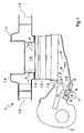
- Figure 1 shows a schematic representation of an air conditioner 1 with several air conditioning modules 1.1 to 1.4, z.
- an evaporator 1.1 As an evaporator 1.1, a heater 1.2, optionally a filter 1.3 and an air duct 1.4.
- the air conditioner 1 extends, for example, in at least two orientations.
- FIG. 1 shows an exemplary embodiment of an extension of the air conditioning system 1 in the X and Y directions.
- the X-direction is understood to mean the orientation of the air conditioning system along the vehicle's longitudinal axis.
- Y-direction is the orientation along the vehicle transverse axis.
- the Z direction is understood to mean the orientation of the air conditioning system 1 along the vertical axis upwards or downwards.
- the air duct 1.4 is arranged for this purpose, for example, as a cross member between the A-pillars of the vehicle.
- Flow inlet side or suction side of the air duct 1.4 runs from a fan 2 coming in the X direction in the evaporator 1.1.
- a partial air flow TL is branched off from the main air flow HL via a branch line 4 and fed to an air treatment module 6.
- the branch line 4 is designed in the manner of a bypass line.
- the air treatment module 6 is designed, for example, as a conventional ozone module for generating ozone O, which admits the diverted partial air flow TL to the ozone O.
- a conventional ozone module is for example from DE 199 19 623 A1 known.
- the offset with the ozone O partial air flow TLO is the air duct 1.4 and thus the main air flow HL before the evaporator 1.1 is supplied again.
- the air treatment module 6 may comprise, in a manner not shown, an ionization module for ionizing the air and / or a filter unit for filtering the air.
- the branch line 4 opens into at least one flow inlet 8.1 for the air duct 4.
- the flow inlet 8.1 is for example designed as a provided with multiple openings 8.1 ring 8, which surrounds the air duct 1.4 ,
- the ring line 8 is arranged at a predetermined and the flow conditions of the main air flow HL consideration point on the air duct 4, so that the main air flow HL and the ozone-displaced partial air flow TLO sufficiently well mixed to a ozone-displaced main air stream HLO and the flow side subsequent components or components of the air conditioner 1, in particular the evaporator 1.1 be largely applied over the entire surface with the mixture of the main air flow HL and ozone-displaced partial air flow TLO. This ensures a constant sterilization of the evaporator 1.1.
- Figure 2 shows the arranged around the air duct 1.4 ring line 8 in cross section.
- FIG. 2 shows the arranged around the air duct 1.4 ring line 8 in cross section.
- several openings 8.1 are provided in the manner of injection points, via which the ozone-displaced partial air flow TLO the main air flow HL is supplied.
- a further auxiliary fan 10 can additionally be arranged in the branch line 4 before or after the air treatment module 6.
- the ring line 8 can be replaced by suitable channels or other air ducts.
- the partial air flow TL at a suitable location of the air duct 1.4, in particular against a pressure drop Afflucted component of the air conditioner 1, z. B. an air filter 1.6, are diverted.
- the supply of the ozone-displaced partial air flow TLO takes place after the air filter 1.6 and before the evaporator 1.1.
- the air treatment module 6 may be arranged in a manner not shown between the air filter 1.6 and the evaporator 1.1 in a branch line 4.
- branch line 4 branches off in a region of the air duct 1.4, which has a corresponding pressure gradient, so that the partial air flow TL can be diverted from the main air flow HL. Also in this embodiment can be dispensed with an auxiliary fan.
- the supply of the ozone-displaced partial air flow TL is preferably carried out before the evaporator 1.1 via one or more flow inputs 8.1.
Applications Claiming Priority (1)
| Application Number | Priority Date | Filing Date | Title |
|---|---|---|---|
| DE102005048229A DE102005048229A1 (de) | 2005-10-07 | 2005-10-07 | Vorrichtung und Verfahren zur Aufbereitung eines in einem Luftführungskanal geführten Luftstroms einer Klimaanlage |
Publications (3)
| Publication Number | Publication Date |
|---|---|
| EP1772680A2 true EP1772680A2 (fr) | 2007-04-11 |
| EP1772680A3 EP1772680A3 (fr) | 2008-03-12 |
| EP1772680B1 EP1772680B1 (fr) | 2014-03-05 |
Family
ID=37667633
Family Applications (1)
| Application Number | Title | Priority Date | Filing Date |
|---|---|---|---|
| EP06019076.6A Active EP1772680B1 (fr) | 2005-10-07 | 2006-09-12 | Dispositif et procédé de traitement d'air dans un canal de conduite d'un dispositif de climatisation |
Country Status (2)
| Country | Link |
|---|---|
| EP (1) | EP1772680B1 (fr) |
| DE (1) | DE102005048229A1 (fr) |
Cited By (1)
| Publication number | Priority date | Publication date | Assignee | Title |
|---|---|---|---|---|
| FR2933907A1 (fr) * | 2008-07-21 | 2010-01-22 | Renault Sas | Systeme de traitement d'air pour vehicule automobile |
Families Citing this family (3)
| Publication number | Priority date | Publication date | Assignee | Title |
|---|---|---|---|---|
| DE102008049278A1 (de) | 2008-09-26 | 2010-04-01 | Behr Gmbh & Co. Kg | Mehrzonenklimaanlage |
| DE102008050814A1 (de) | 2008-10-08 | 2010-04-15 | Behr Gmbh & Co. Kg | Kraftfahrzeugklimaanlage |
| DE102012201388A1 (de) * | 2012-01-31 | 2013-08-01 | Behr Gmbh & Co. Kg | Klimatisierungseinrichtung |
Citations (6)
| Publication number | Priority date | Publication date | Assignee | Title |
|---|---|---|---|---|
| US3750556A (en) * | 1971-08-23 | 1973-08-07 | Air Guard Inc | Air purifying means |
| DE3637702A1 (de) * | 1986-11-05 | 1988-05-19 | Peter Fuchs | Vorrichtung zum absenken des keimspiegels in raumluft mittels ultravioletter strahlung |
| JPH02302536A (ja) * | 1989-05-17 | 1990-12-14 | Daikin Ind Ltd | 空調装置 |
| US5904896A (en) * | 1995-12-08 | 1999-05-18 | A. R. Grindl | Multi-stage zonal air purification system |
| EP1079183A2 (fr) * | 1999-08-26 | 2001-02-28 | Beghelli S.p.A. | Dispositif de climatisation avec assainissement d'air automatique et procédé correspondant |
| US20050168907A1 (en) * | 2000-08-28 | 2005-08-04 | Sharp Kabushiki Kaisha | Air conditioning apparatus and ion generating device for use therein |
Family Cites Families (6)
| Publication number | Priority date | Publication date | Assignee | Title |
|---|---|---|---|---|
| DE19531518A1 (de) * | 1995-08-26 | 1997-02-27 | Benno Kurtz | Verfahren und Vorrichtung zur Frischluft-Neutralisation |
| DE19919623A1 (de) * | 1999-04-29 | 2000-11-02 | T E M Tech Entwicklungen Und M | Luftaufbereitungssystem zum wirksamen Abbau von luftgetragenen Gerüchen, Keimen und Schadstoffen |
| DE10301214B3 (de) * | 2003-01-15 | 2004-04-15 | Carl Freudenberg Kg | Anordnung zur Aufbereitung von Luft |
| DE10317514B3 (de) * | 2003-04-16 | 2004-08-26 | Daimlerchrysler Ag | Klimaanlage |
| JP2005289177A (ja) * | 2004-03-31 | 2005-10-20 | Calsonic Kansei Corp | 空調装置 |
| ITMI20042288A1 (it) | 2004-11-26 | 2005-02-26 | Riccardo Bolzani | Dispositivo di profumazione per impianti di condizionamento |
-
2005
- 2005-10-07 DE DE102005048229A patent/DE102005048229A1/de not_active Withdrawn
-
2006
- 2006-09-12 EP EP06019076.6A patent/EP1772680B1/fr active Active
Patent Citations (6)
| Publication number | Priority date | Publication date | Assignee | Title |
|---|---|---|---|---|
| US3750556A (en) * | 1971-08-23 | 1973-08-07 | Air Guard Inc | Air purifying means |
| DE3637702A1 (de) * | 1986-11-05 | 1988-05-19 | Peter Fuchs | Vorrichtung zum absenken des keimspiegels in raumluft mittels ultravioletter strahlung |
| JPH02302536A (ja) * | 1989-05-17 | 1990-12-14 | Daikin Ind Ltd | 空調装置 |
| US5904896A (en) * | 1995-12-08 | 1999-05-18 | A. R. Grindl | Multi-stage zonal air purification system |
| EP1079183A2 (fr) * | 1999-08-26 | 2001-02-28 | Beghelli S.p.A. | Dispositif de climatisation avec assainissement d'air automatique et procédé correspondant |
| US20050168907A1 (en) * | 2000-08-28 | 2005-08-04 | Sharp Kabushiki Kaisha | Air conditioning apparatus and ion generating device for use therein |
Cited By (2)
| Publication number | Priority date | Publication date | Assignee | Title |
|---|---|---|---|---|
| FR2933907A1 (fr) * | 2008-07-21 | 2010-01-22 | Renault Sas | Systeme de traitement d'air pour vehicule automobile |
| WO2010010289A1 (fr) * | 2008-07-21 | 2010-01-28 | Renault S.A.S. | Systeme de traitement d'air pour vehicule automobile |
Also Published As
| Publication number | Publication date |
|---|---|
| EP1772680B1 (fr) | 2014-03-05 |
| DE102005048229A1 (de) | 2007-04-12 |
| EP1772680A3 (fr) | 2008-03-12 |
Similar Documents
| Publication | Publication Date | Title |
|---|---|---|
| EP1772680B1 (fr) | Dispositif et procédé de traitement d'air dans un canal de conduite d'un dispositif de climatisation | |
| WO2007087848A2 (fr) | Dispositif de déviation, machine comportant un tel dispositif de déviation et procédé de transport et de déviation d'au moins un écheveau de mèche pour filtre | |
| DE102015113785B4 (de) | Kühlluftschnittstelle in einem Gebläsegehäuse | |
| DE102017215462B4 (de) | Klimaanlage eines Fahrzeugs | |
| DE102017215457A1 (de) | Klimaanlage eines Fahrzeugs | |
| EP2937633A1 (fr) | Dispositif de purification d'air, dispositif d'aération et procédé de purification d'air | |
| EP2117856A1 (fr) | Procédé de climatisation d'un véhicule | |
| DE10209837A1 (de) | Klimagebläse | |
| DE102020119222A1 (de) | Luftreinigungseinrichtung, Tiermastanlage und Verwendung | |
| DE102012111148B4 (de) | Dekontaminationsanordnung sowie Verfahren zum Betreiben einer solchen | |
| EP3703869A1 (fr) | Dispositif pour nébuliser un liquide de rinçage | |
| EP3244934B1 (fr) | Système de décontamination | |
| DE102014209452A1 (de) | Klimaanlage mit Bypassvorrichtung | |
| DE10147114B4 (de) | Vorrichtung und Verfahren zum Temperieren und Belüften von Kraftfahrzeugen | |
| DE102012203625A1 (de) | Innenraumfiltersystem | |
| EP3406977B1 (fr) | Purificateur d'air intérieur | |
| EP3065993B1 (fr) | Procédé de climatisation d'un véhicule, en particulier d'un véhicule ferroviaire | |
| DE102008033806A1 (de) | Belüftungseinrichtung mit Duftstoffbehälter | |
| DE102019201012A1 (de) | Kraftfahrzeug | |
| DE102019213430A1 (de) | Trennvorrichtung, Behandlungsanlage, Verfahren zum Trennen zweier Raumbereiche und Verfahren zum Behandeln von Werkstücken | |
| DE102020107981A1 (de) | Vorrichtung zur Desinfektion von Gegenständen oder Feststoffen, vorzugsweise von Schutzausrüstungsteilen, und deren Verwendung | |
| DE102010043334A1 (de) | Klimaanlage für ein Kraftfahrzeug | |
| DE102008039089A1 (de) | Belüftungseinrichtung | |
| DE102020210305A1 (de) | Verfahren zum Betreiben einer Beduftungseinrichtung | |
| DE102019007536A1 (de) | Vorrichtung zur Verbesserung einer Innenraum-Luftqualität in einem Fahrzeug sowie ein Fahrzeug |
Legal Events
| Date | Code | Title | Description |
|---|---|---|---|
| PUAI | Public reference made under article 153(3) epc to a published international application that has entered the european phase |
Free format text: ORIGINAL CODE: 0009012 |
|
| AK | Designated contracting states |
Kind code of ref document: A2 Designated state(s): AT BE BG CH CY CZ DE DK EE ES FI FR GB GR HU IE IS IT LI LT LU LV MC NL PL PT RO SE SI SK TR |
|
| AX | Request for extension of the european patent |
Extension state: AL BA HR MK YU |
|
| PUAL | Search report despatched |
Free format text: ORIGINAL CODE: 0009013 |
|
| AK | Designated contracting states |
Kind code of ref document: A3 Designated state(s): AT BE BG CH CY CZ DE DK EE ES FI FR GB GR HU IE IS IT LI LT LU LV MC NL PL PT RO SE SI SK TR |
|
| AX | Request for extension of the european patent |
Extension state: AL BA HR MK YU |
|
| 17P | Request for examination filed |
Effective date: 20080912 |
|
| AKX | Designation fees paid |
Designated state(s): DE FR GB IT SE |
|
| 17Q | First examination report despatched |
Effective date: 20081113 |
|
| GRAP | Despatch of communication of intention to grant a patent |
Free format text: ORIGINAL CODE: EPIDOSNIGR1 |
|
| INTG | Intention to grant announced |
Effective date: 20130920 |
|
| GRAS | Grant fee paid |
Free format text: ORIGINAL CODE: EPIDOSNIGR3 |
|
| GRAA | (expected) grant |
Free format text: ORIGINAL CODE: 0009210 |
|
| AK | Designated contracting states |
Kind code of ref document: B1 Designated state(s): DE FR GB IT SE |
|
| REG | Reference to a national code |
Ref country code: GB Ref legal event code: FG4D Free format text: NOT ENGLISH |
|
| REG | Reference to a national code |
Ref country code: DE Ref legal event code: R096 Ref document number: 502006013561 Country of ref document: DE Effective date: 20140417 |
|
| PG25 | Lapsed in a contracting state [announced via postgrant information from national office to epo] |
Ref country code: SE Free format text: LAPSE BECAUSE OF FAILURE TO SUBMIT A TRANSLATION OF THE DESCRIPTION OR TO PAY THE FEE WITHIN THE PRESCRIBED TIME-LIMIT Effective date: 20140305 |
|
| REG | Reference to a national code |
Ref country code: DE Ref legal event code: R026 Ref document number: 502006013561 Country of ref document: DE |
|
| PLBI | Opposition filed |
Free format text: ORIGINAL CODE: 0009260 |
|
| PLAX | Notice of opposition and request to file observation + time limit sent |
Free format text: ORIGINAL CODE: EPIDOSNOBS2 |
|
| 26 | Opposition filed |
Opponent name: VALEO SYSTEMES THERMIQUES Effective date: 20141205 |
|
| REG | Reference to a national code |
Ref country code: DE Ref legal event code: R026 Ref document number: 502006013561 Country of ref document: DE Effective date: 20141205 |
|
| RAP2 | Party data changed (patent owner data changed or rights of a patent transferred) |
Owner name: MAHLE BEHR GMBH & CO. KG |
|
| REG | Reference to a national code |
Ref country code: DE Ref legal event code: R082 Ref document number: 502006013561 Country of ref document: DE Representative=s name: GRAUEL, ANDREAS, DIPL.-PHYS. DR. RER. NAT., DE |
|
| PG25 | Lapsed in a contracting state [announced via postgrant information from national office to epo] |
Ref country code: IT Free format text: LAPSE BECAUSE OF FAILURE TO SUBMIT A TRANSLATION OF THE DESCRIPTION OR TO PAY THE FEE WITHIN THE PRESCRIBED TIME-LIMIT Effective date: 20140305 |
|
| REG | Reference to a national code |
Ref country code: DE Ref legal event code: R081 Ref document number: 502006013561 Country of ref document: DE Owner name: MAHLE INTERNATIONAL GMBH, DE Free format text: FORMER OWNER: BEHR GMBH & CO. KG, 70469 STUTTGART, DE Effective date: 20150325 Ref country code: DE Ref legal event code: R081 Ref document number: 502006013561 Country of ref document: DE Owner name: MAHLE INTERNATIONAL GMBH, DE Free format text: FORMER OWNER: BEHR GMBH & CO. KG, 70469 STUTTGART, DE Effective date: 20140306 Ref country code: DE Ref legal event code: R082 Ref document number: 502006013561 Country of ref document: DE Representative=s name: GRAUEL, ANDREAS, DIPL.-PHYS. DR. RER. NAT., DE Effective date: 20150325 |
|
| PLAF | Information modified related to communication of a notice of opposition and request to file observations + time limit |
Free format text: ORIGINAL CODE: EPIDOSCOBS2 |
|
| GBPC | Gb: european patent ceased through non-payment of renewal fee |
Effective date: 20140912 |
|
| PLBB | Reply of patent proprietor to notice(s) of opposition received |
Free format text: ORIGINAL CODE: EPIDOSNOBS3 |
|
| PG25 | Lapsed in a contracting state [announced via postgrant information from national office to epo] |
Ref country code: GB Free format text: LAPSE BECAUSE OF NON-PAYMENT OF DUE FEES Effective date: 20140912 |
|
| REG | Reference to a national code |
Ref country code: DE Ref legal event code: R100 Ref document number: 502006013561 Country of ref document: DE |
|
| PLCK | Communication despatched that opposition was rejected |
Free format text: ORIGINAL CODE: EPIDOSNREJ1 |
|
| REG | Reference to a national code |
Ref country code: FR Ref legal event code: PLFP Year of fee payment: 11 |
|
| PLBN | Opposition rejected |
Free format text: ORIGINAL CODE: 0009273 |
|
| STAA | Information on the status of an ep patent application or granted ep patent |
Free format text: STATUS: OPPOSITION REJECTED |
|
| 27O | Opposition rejected |
Effective date: 20160622 |
|
| REG | Reference to a national code |
Ref country code: FR Ref legal event code: PLFP Year of fee payment: 12 |
|
| REG | Reference to a national code |
Ref country code: FR Ref legal event code: PLFP Year of fee payment: 13 |
|
| PGFP | Annual fee paid to national office [announced via postgrant information from national office to epo] |
Ref country code: FR Payment date: 20180924 Year of fee payment: 13 |
|
| PG25 | Lapsed in a contracting state [announced via postgrant information from national office to epo] |
Ref country code: FR Free format text: LAPSE BECAUSE OF NON-PAYMENT OF DUE FEES Effective date: 20190930 |
|
| REG | Reference to a national code |
Ref country code: DE Ref legal event code: R079 Ref document number: 502006013561 Country of ref document: DE Free format text: PREVIOUS MAIN CLASS: F24F0003160000 Ipc: F24F0008000000 |
|
| PGFP | Annual fee paid to national office [announced via postgrant information from national office to epo] |
Ref country code: DE Payment date: 20230920 Year of fee payment: 18 |