EP1772637A2 - Saugfuß für Geräteträger oder dergleichen - Google Patents
Saugfuß für Geräteträger oder dergleichen Download PDFInfo
- Publication number
- EP1772637A2 EP1772637A2 EP06020824A EP06020824A EP1772637A2 EP 1772637 A2 EP1772637 A2 EP 1772637A2 EP 06020824 A EP06020824 A EP 06020824A EP 06020824 A EP06020824 A EP 06020824A EP 1772637 A2 EP1772637 A2 EP 1772637A2
- Authority
- EP
- European Patent Office
- Prior art keywords
- housing
- separating element
- membrane
- edge
- suction membrane
- Prior art date
- Legal status (The legal status is an assumption and is not a legal conclusion. Google has not performed a legal analysis and makes no representation as to the accuracy of the status listed.)
- Granted
Links
- 239000012528 membrane Substances 0.000 claims abstract description 28
- 229910052751 metal Inorganic materials 0.000 claims abstract description 9
- 239000002184 metal Substances 0.000 claims abstract description 9
- 230000007246 mechanism Effects 0.000 claims abstract description 4
- 239000011888 foil Substances 0.000 claims abstract description 3
- 239000000463 material Substances 0.000 claims description 7
- 239000004952 Polyamide Substances 0.000 claims description 6
- 229920002647 polyamide Polymers 0.000 claims description 6
- 239000004033 plastic Substances 0.000 claims description 5
- 229920003023 plastic Polymers 0.000 claims description 5
- 239000004014 plasticizer Substances 0.000 claims description 4
- 239000000853 adhesive Substances 0.000 claims description 2
- 238000004026 adhesive bonding Methods 0.000 claims description 2
- 230000001070 adhesive effect Effects 0.000 claims description 2
- 239000004744 fabric Substances 0.000 claims description 2
- 239000004753 textile Substances 0.000 claims description 2
- 229920012485 Plasticized Polyvinyl chloride Polymers 0.000 claims 1
- 229920000915 polyvinyl chloride Polymers 0.000 claims 1
- 230000005855 radiation Effects 0.000 abstract description 3
- 210000002445 nipple Anatomy 0.000 description 7
- 230000002745 absorbent Effects 0.000 description 3
- 239000002250 absorbent Substances 0.000 description 3
- 244000261422 Lysimachia clethroides Species 0.000 description 1
- 229910052782 aluminium Inorganic materials 0.000 description 1
- XAGFODPZIPBFFR-UHFFFAOYSA-N aluminium Chemical compound [Al] XAGFODPZIPBFFR-UHFFFAOYSA-N 0.000 description 1
- 230000015572 biosynthetic process Effects 0.000 description 1
- 238000002788 crimping Methods 0.000 description 1
- 230000007423 decrease Effects 0.000 description 1
- 230000001419 dependent effect Effects 0.000 description 1
- 238000004049 embossing Methods 0.000 description 1
- 229920001690 polydopamine Polymers 0.000 description 1
Images
Classifications
-
- F—MECHANICAL ENGINEERING; LIGHTING; HEATING; WEAPONS; BLASTING
- F16—ENGINEERING ELEMENTS AND UNITS; GENERAL MEASURES FOR PRODUCING AND MAINTAINING EFFECTIVE FUNCTIONING OF MACHINES OR INSTALLATIONS; THERMAL INSULATION IN GENERAL
- F16B—DEVICES FOR FASTENING OR SECURING CONSTRUCTIONAL ELEMENTS OR MACHINE PARTS TOGETHER, e.g. NAILS, BOLTS, CIRCLIPS, CLAMPS, CLIPS OR WEDGES; JOINTS OR JOINTING
- F16B47/00—Suction cups for attaching purposes; Equivalent means using adhesives
- F16B47/006—Suction cups for attaching purposes; Equivalent means using adhesives the suction cups being activated by the rotation of a cranked lever arm
-
- F—MECHANICAL ENGINEERING; LIGHTING; HEATING; WEAPONS; BLASTING
- F16—ENGINEERING ELEMENTS AND UNITS; GENERAL MEASURES FOR PRODUCING AND MAINTAINING EFFECTIVE FUNCTIONING OF MACHINES OR INSTALLATIONS; THERMAL INSULATION IN GENERAL
- F16B—DEVICES FOR FASTENING OR SECURING CONSTRUCTIONAL ELEMENTS OR MACHINE PARTS TOGETHER, e.g. NAILS, BOLTS, CIRCLIPS, CLAMPS, CLIPS OR WEDGES; JOINTS OR JOINTING
- F16B47/00—Suction cups for attaching purposes; Equivalent means using adhesives
-
- B—PERFORMING OPERATIONS; TRANSPORTING
- B60—VEHICLES IN GENERAL
- B60R—VEHICLES, VEHICLE FITTINGS, OR VEHICLE PARTS, NOT OTHERWISE PROVIDED FOR
- B60R11/00—Arrangements for holding or mounting articles, not otherwise provided for
- B60R2011/0042—Arrangements for holding or mounting articles, not otherwise provided for characterised by mounting means
- B60R2011/0049—Arrangements for holding or mounting articles, not otherwise provided for characterised by mounting means for non integrated articles
- B60R2011/005—Connection with the vehicle part
- B60R2011/0056—Connection with the vehicle part using suction cups
Definitions
- the invention relates to a squeegee for equipment carrier or the like, as often found in motor vehicles for holding small computers (so-called PDAs), mobile navigation devices, mobile phones and the like.
- PDAs small computers
- mobile navigation devices mobile phones and the like.
- For mounting such device holder in the vehicle is often or mainly the windshield, because it provides an absolutely smooth surface and it allows the attachment of the respective device in the field of vision of the driver.
- the squeegee usually consists of a housing made of hard plastic and a suction membrane forming the bottom of a soft plastic.
- the nipple membrane is centrally connected to a shaft of an actuating mechanism, with which the nipple membrane by means of an actuating lever between an inoperative position and a suction position is movable.
- the nipple membrane is usually made of PVC, which must necessarily contain plasticizer. Especially when exposed to heat, so in particular sunlight, occurs unwanted release of plasticizer from the PVC material of the absorbent membrane instead. This leads, inter alia, that the absorbent membrane, especially at local temperatures from about 60 ° C, glued to the edge of the housing. This obstructs the mobility of the nipple membrane, impairs the function of the squeegee, and sooner or later makes the squeegee unusable.
- the object of the invention is to remedy this problem.
- a separating element is arranged between the edge of the housing and the suction membrane, which prevents the adhesive membrane from sticking to the edge of the housing.
- the separating element is extended to a lining of the housing inner wall and formed as a reflective element to reflect heat radiation.
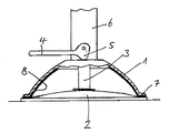
- the suction shown schematically in the drawing which is shown in its working position, ie its suction position, consists of a housing 1 made of hard plastic, a suction membrane 2 made of PVC, and an actuating mechanism, one with its lower end to the central region of the suction membrane 2 connected to the shaft 3 and thus connected via a joint 4 operating lever 4 with an eccentric cam 5 supported on the housing.
- a connecting element 6 Connected to the housing 1, for example by integral formation, is a connecting element 6, in the exemplary embodiment in the form of a sleeve for connecting the suction foot to another component, for example a gooseneck.
- a spring for biasing the nipple membrane in its rest position is not shown and may be housed within the sleeve 6 and act on the upper end of the shaft 3.
- a separating element 8 is arranged, which is fixed to the housing 1.
- the separating element 8 covers at least the edge region 7 of the housing 1, which is supported in the suction position of the squeegee at the top of the suction membrane 2.
- the separating element 8 may, in particular if it is designed as a reflective separating element, extend from the edge 7 inwardly over a part of the inner wall or the entire inner wall of the housing 1, as shown in the embodiment.
- the separating element 8 may be made of metal as a reflective element which reflects radiation, in particular of aluminum, as a thin metal sheet or as a metal foil, and may be produced by gluing, mechanically, e.g. by crimping the edge or indenting the edge at individual circumferential locations, or otherwise connecting the housing edge or housing inner panel.
- the cooperating with the nipple membrane surface area of the metal separator may also be profiled, for example with a Noppcn tenugung or preferably with a groove embossing of radially extending ribs / grooves, which is achieved that the actual contact area between the (heat-conducting) metal and the PVC nipple membrane decreases becomes.
- the separating element may be designed as a ring limited only to the edge of the housing in the form of a thin annular disk of polyamide, since polyamide does not bond with PVC.
- a polyamide ring can be clipped onto the edge of the housing like a shoe or pressed into it.
- a conceivable design of the whole polyamide housing, however, would not be desirable, since polyamide on the one hand looks visually not good and on the other can be glued with no other plastic, which creates assembly problems.
- separating elements 8 are possible, for example, an intermediate layer of textile fabric or the like. Possible further materials can also be determined by tests. It is only important that a sticking of the PVC material of the absorbent membrane is avoided in the release of plasticizers by heat with the edge of the housing.
Landscapes
- Engineering & Computer Science (AREA)
- General Engineering & Computer Science (AREA)
- Mechanical Engineering (AREA)
- Hooks, Suction Cups, And Attachment By Adhesive Means (AREA)
- External Artificial Organs (AREA)
- Accommodation For Nursing Or Treatment Tables (AREA)
- Table Devices Or Equipment (AREA)
- Packages (AREA)
- Sheets, Magazines, And Separation Thereof (AREA)
- Manipulator (AREA)
Abstract
Description
- Die Erfindung betrifft einen Saugfuß für Geräteträger oder dergleichen, wie sie häufig in Kraftfahrzeugen zur Halterung von Kleincomputern (sogenannten PDAs), mobilen Navigationsgeräten, Mobiltelefonen und dergleichen Anwendung finden. Zum Anbringen solcher Gerätehalter im Fahrzeug dient häufig oder vorwiegend die Windschutzscheibe, weil sie eine absolut glatte Fläche bietet und sie das Anbringen des jeweiligen Geräts im Blickfeld des Fahrers ermöglicht.
- Das Anbringen des Saugfußes eines solchen Gerätehalters an der Windschutzscheibe bedeutet aber auch, daß der Saugfuß in besonders starkem Maße der Sonneneinstrahlung ausgesetzt ist, was für Fahrt und Stand des Fahrzeugs gleichermaßen gilt. Der Saugfuß besteht üblicherweise aus einem Gehäuse aus hartem Kunststoff und einer dessen Boden bildenden Saugermembran aus einem weichen Kunststoff. Die Saugermembran ist mittig mit einem Schaft eines Betätigungsmechanismus verbunden, mit welchem die Saugermembran mittels eines Betätigungshebels zwischen einer unwirksamen Stellung und einer Saugstellung bewegbar ist.
- Die Saugermembran besteht üblicherweise aus PVC, das notwendigerweise Weichmacher enthalten muß. Gerade bei Wärmeeinwirkung, also insbesondere bei Sonneneinstrahlung, tritt ein unerwünschtes Freisetzen von Weichmacher aus dem PVC-Material der Saugermembran statt. Dies führt unter anderem dazu, daß die Saugermembran, namentlich bei lokalen Temperaturen ab etwa 60°C, mit dem Gehäuserand verklebt. Dies behindert die Beweglichkeit der Saugermembran, beeinträchtigt die Funktion des Saugfußes, und führt über kurz oder lang zum Unbrauchbarwerden des Saugfußes.
- Aufgabe der Erfindung ist es, diesem Problem abzuhelfen.
- Diese Aufgabe wird gemäß der Erfindung durch die im Anspruch 1 angegebene Anordnung gelöst. Vorteilhafte Ausgestaltungen der Erfindung sind Gegenstand der Unteransprüche.
- Erfindungsgemäß wird zwischen dem Gehäuserand und der Saugermembran ein Trennelement angeordnet, das die Verklebung der Saugermembran mit dem Gehäuserand verhindert. Mehrere Ausführungsmöglichkeiten dazu sind nachstehend in der Beispielsbeschreibung erläutert.
- In vorteilhafter Weiterbildung der Erfindung ist das Trennelement zu einer Auskleidung der Gehäuseinnenwand erweitert und als reflektives Element ausgebildet, um Wärmeeinstrahlung zu reflektieren.
- Die Erfindung wird nachstehend unter Bezugnahme auf die anliegende schematische Zeichnung mehr im einzelnen beschrieben, die einen schematisierten vereinfachten Schnitt durch einen Saugfuß nach der Erfindung zeigt.
- Der in der Zeichnung schematisch dargestellte Saugfuß, der in seiner Arbeitsstellung, also seiner Saugstellung, dargestellt ist, besteht aus einem Gehäuse 1 aus hartem Kunststoff, einer Saugermembran 2 aus PVC, und einem Betätigungsmechanismus, der einen mit seinem unteren Ende mit dem Mittenbereich der Saugermembran 2 verbundenen Schaft 3 und einem damit über ein Gelenk 4 verbundenen Betätigungshebel 4 mit einem sich auf dem Gehäuse abstützenden Exzenternocken 5 umfaßt. Mit dem Gehäuse 1 beispielsweise durch einstückige Ausbildung verbunden ist ein Anschlusselement 6, beim Ausführungsbeispiel in Gestalt einer Hülse zur Verbindung des Saugfußes mit einer anderen Komponente, beispielsweise einen Schwanenhals. Eine Feder zur Vorspannung der Saugermembran in ihrer Ruhestellung ist nicht dargestellt und kann innerhalb der Hülse 6 untergebracht sein und auf das obere Ende des Schafts 3 wirken.
- Zwischen dem unteren Rand 7 des Gehäuses 1 und der Saugermembran 2 ist ein Trennelement 8 angeordnet, das am Gehäuse 1 fixiert ist. Das Trennelement 8 überdeckt mindestens den Randbereich 7 des Gehäuses 1, der sich in der Saugstellung des Saugfußes an der Oberseite der Saugermembran 2 abstützt. Das Trennelement 8 kann aber, insbesondere wenn es als reflektives Trennelement ausgebildet ist, sich vom Rand 7 aus einwärts über einen Teil der Innenwand oder die ganze Innenwand des Gehäuses 1 erstrecken, wie beim Ausführungsbeispiel dargestellt ist.
- Das Trennelement 8 kann als reflektives Element, das Einstrahlung reflektiert, aus Metall hergestellt sein, insbesondere aus Aluminium, und zwar als dünnes Metallblech oder als Metallfolie, und kann durch Kleben, mechanisch, z.B. durch Umbördeln des Rands oder des Eindrückens des Rands an einzelnen Umfangsstellen, oder auf andere Weise mit dem Gehäuserand oder der Gehäuseinnenwandfläche verbunden werden. Der mit der Saugermembran zusammenwirkende Flächenbereich des metallenen Trennelements kann außerdem profiliert sein, beispielsweise mit einer Noppcnprägung oder vorzugsweise mit einer Rillenprägung von radial verlaufenden Rippen/Rillen, womit erreicht wird, daß die tatsächliche Berührungsfläche zwischen dem (wärmeleitenden) Metall und der PVC-Saugermembran verkleinert wird.
- Alternativ kann das Trennelement als nur auf den Gehäuserand beschränkten Ring in Gestalt einer dünnen Ringscheibe aus Polyamid ausgebildet sein, da Polyamid sich nicht mit PVC verbindet. Ein solcher Polyamidring kann schuhartig auf den Gehäuserand aufgeklipst oder in diesen eingepresst sein. Eine denkbare Ausbildung des ganzen Gehäuses aus Polyamid wäre hingegen nicht wünschenswert, da Polyamid zum einen optisch nicht gut aussieht und zum anderen sich mit keinem anderen Kunststoff verkleben lässt, was Montageprobleme schafft.
- Es versteht sich, daß weitere Ausführungsformen von Trennelementen 8 möglich sind, beispielsweise auch eine Zwischenlage aus textilem Gewebe oder dergleichen. Mögliche weitere Materialien können auch durch Versuche ermittelt werden. Es kommt lediglich darauf an, daß ein Verkleben des PVC-Materials der Saugermembran beim Freisetzen von Weichmachern durch Wärmeeinwirkung mit dem Gehäuserand vermieden wird.
Claims (8)
- Saugfuß für Geräteträger oder dergleichen, bestehend aus einem Gehäuse (1) aus hartem Kunststoff, einer Saugermembran (2) aus weichmacherhaltigem PVC, und einem Betätigungsmechanismus (3, 4) zur Betätigung der Saugermembran (2) zwischen einer Lösestellung und einer Arbeitsstellung, dadurch gekennzeichnet, daß zwischen dem Gehäuse (1) und der Saugermembran (2) ein mindestens den mit der Saugermembran in Berührung kommenden Rand (7) des Gehäuses (1) abdeckendes Trennelement (8) aus einem mit dem PVC-Material der Saugermembran (2) bei Wärmeeinwirkung und/oder Freisetzung von Weichmachern nicht verklebenden Material angeordnet und am Gehäuse fixiert ist.
- Saugfuß nach Anspruch 1, wobei das Trennelement (8) aus Metallblech oder Metallfolie besteht.
- Saugfuß nach Anspruch 2, wobei das Trennelement nicht nur den Gehäuserand (7) überdeckt sondern sich auch teilweise oder ganz über die Innenwand des Gehäuses (1) erstreckt und als Reflektor für einfallende Strahlen dient.
- Saugfuß nach Anspruch 1, wobei das Trennelement (8) aus Polyamid besteht.
- Saugfuß nach einem der Ansprüche 2 bis 4, wobei die der Saugermembran zugewandte Fläche des Trennelements (8) mit einer Profilierung zur Verringerung der tatsächlichen Berührungsfläche zwischen dem Trennelement (8) und der Saugermembran (2) versehen ist.
- Saugfuß nach Anspruch 5, wobei die Profilierung in Gestalt eines radialen Rillen/Rippen-Musters ausgebildet ist.
- Saugfuß nach Anspruch 1, wobei das Trennelement (8) aus einem Gewebe oder anderem textilen Material besteht.
- Saugfuß nach einem der Ansprüche 1 bis 7, wobei das Trennelement (8) durch Verkleben oder mechanische Befestigung wie Einpressen, Anklipsen, Bördeln oder örtliche Verformung mit dem Gehäuse (1) oder Gehäuserand (7) verbunden ist.
Applications Claiming Priority (1)
| Application Number | Priority Date | Filing Date | Title |
|---|---|---|---|
| DE102005047809A DE102005047809A1 (de) | 2005-10-05 | 2005-10-05 | Saugfuß für Geräteträger oder dergleichen |
Publications (3)
| Publication Number | Publication Date |
|---|---|
| EP1772637A2 true EP1772637A2 (de) | 2007-04-11 |
| EP1772637A3 EP1772637A3 (de) | 2008-07-02 |
| EP1772637B1 EP1772637B1 (de) | 2010-12-29 |
Family
ID=37636641
Family Applications (1)
| Application Number | Title | Priority Date | Filing Date |
|---|---|---|---|
| EP06020824A Not-in-force EP1772637B1 (de) | 2005-10-05 | 2006-10-04 | Saugfuß für Geräteträger oder dergleichen |
Country Status (7)
| Country | Link |
|---|---|
| US (2) | US7293750B2 (de) |
| EP (1) | EP1772637B1 (de) |
| KR (1) | KR20070038413A (de) |
| CN (1) | CN1945031B (de) |
| AT (1) | ATE493585T1 (de) |
| DE (3) | DE102005047809A1 (de) |
| TW (1) | TW200724814A (de) |
Cited By (4)
| Publication number | Priority date | Publication date | Assignee | Title |
|---|---|---|---|---|
| USD888979S1 (en) | 2020-01-23 | 2020-06-30 | Lure Enterprises Limited Liability Company | Cupping device |
| USD888972S1 (en) | 2020-01-23 | 2020-06-30 | Lure Enterprises Limited Liability Company | Cupping device |
| USD893038S1 (en) | 2020-01-23 | 2020-08-11 | Lure Enterprises Limited Liability Company | Cupping device |
| USD893037S1 (en) | 2020-01-23 | 2020-08-11 | Lure Enterprises Limited Liability Company | Cupping device |
Families Citing this family (30)
| Publication number | Priority date | Publication date | Assignee | Title |
|---|---|---|---|---|
| US20060249638A1 (en) * | 2005-05-03 | 2006-11-09 | Jim Ehrke | Removably attachable shower bar |
| NL1029660C2 (nl) * | 2005-08-02 | 2007-02-05 | Tomtom Int Bv | Houder voor het plaatsen van een apparaat, zoals een draagframe voor een telefoon of een navigatieapparaat, aan een oppervlak. |
| DE102005047809A1 (de) * | 2005-10-05 | 2007-04-12 | Harald Richter | Saugfuß für Geräteträger oder dergleichen |
| DE202006007395U1 (de) * | 2006-05-08 | 2006-08-31 | Richter, Harald | Vakuumsaughalter mit Lösestellungsarretierung |
| TWI307385B (en) * | 2006-06-01 | 2009-03-11 | Mitac Int Corp | Suction cup structure |
| US7516926B2 (en) * | 2006-06-16 | 2009-04-14 | Comart Corporation | Suction disc unit |
| JP2008051296A (ja) * | 2006-08-28 | 2008-03-06 | Sony Corp | 吸盤 |
| JP4862559B2 (ja) * | 2006-08-28 | 2012-01-25 | ソニー株式会社 | 吸盤 |
| TWM318683U (en) * | 2006-12-22 | 2007-09-11 | Lite On Technology Corp | Suction plate and removable electronic device fastener with the same |
| TWM322483U (en) * | 2007-03-02 | 2007-11-21 | Lite On Technology Corp | Suction device and detachable electronic device rack having the suction device |
| KR100852164B1 (ko) * | 2007-03-13 | 2008-08-13 | 송순영 | 흡착 기구 |
| DE202007006607U1 (de) * | 2007-05-09 | 2007-07-19 | Chen, Lung-Chih, Tanzih | Verbesserte Struktur eines Saugnapfes |
| US8186366B2 (en) * | 2007-11-26 | 2012-05-29 | Montoya Jerry J | Portable manual car wash assembly |
| TWI401383B (zh) * | 2009-05-05 | 2013-07-11 | Htc Corp | 支架及其吸盤 |
| CN102296794A (zh) * | 2011-07-13 | 2011-12-28 | 钱证光 | 瓷砖搬运器 |
| CN104006276B (zh) * | 2014-05-28 | 2016-04-27 | 严虹桥 | 平板电脑用手持辅助装置 |
| USD755585S1 (en) | 2014-07-30 | 2016-05-10 | National Presto Industries, Inc. | Kitchen utensil |
| US9635983B2 (en) | 2014-07-30 | 2017-05-02 | National Presto Industries, Inc. | Countertop device having retention feature |
| USD755583S1 (en) | 2014-07-30 | 2016-05-10 | National Presto Industries, Inc. | Kitchen utensil |
| US10001245B2 (en) * | 2014-12-08 | 2018-06-19 | The Boeing Company | Apparatus and method for coupling an end effector to a structure |
| USD752054S1 (en) | 2015-03-02 | 2016-03-22 | Clingo.Com Llc | Stand for personal electronic devices |
| TWI655991B (zh) * | 2015-03-26 | 2019-04-11 | 吉生機械股份有限公司 | 移動座及具有移動座之軌道裝置 |
| US9664227B2 (en) * | 2016-04-04 | 2017-05-30 | Canshow Industrial Co., Ltd. | Vacuum retaining device capable of reuse |
| CN106018938B (zh) * | 2016-05-18 | 2019-02-19 | 国家电网公司 | 电抗器在线监测装置 |
| USD876316S1 (en) | 2018-05-23 | 2020-02-25 | Annex Products Pty. Ltd. | Car mount |
| US10649492B2 (en) | 2018-05-31 | 2020-05-12 | Annex Products Pty. Ltd. | Mount for handheld electronic devices |
| WO2021097145A1 (en) | 2019-11-11 | 2021-05-20 | KAFANTARIS, Theologos | Method and apparatus for an adaptable suction device |
| US12503062B2 (en) | 2023-08-08 | 2025-12-23 | Annex Products Pty. Ltd. | Suction mount for a handheld electronic device accessory |
| USD1096368S1 (en) | 2023-08-16 | 2025-10-07 | Annex Products Pty Ltd | Suction mount |
| US12385517B1 (en) * | 2024-05-08 | 2025-08-12 | Suzhou Zewo Import Export Co., Ltd. | Suction cup structure |
Family Cites Families (30)
| Publication number | Priority date | Publication date | Assignee | Title |
|---|---|---|---|---|
| US2047658A (en) * | 1935-12-27 | 1936-07-14 | Zaiger Louis | Suction cup |
| US2730325A (en) * | 1950-07-17 | 1956-01-10 | Dusen Engineering Company Van | Vacuum fixture |
| US3863568A (en) * | 1972-03-27 | 1975-02-04 | Us Navy | Suction fastening device |
| DE2553486A1 (de) * | 1975-11-28 | 1977-06-16 | Ever Clean Gmbh | Vibrationsdaempfer fuer windschutzscheiben |
| US4043531A (en) * | 1976-03-08 | 1977-08-23 | The Raymond Lee Organization, Inc. | Fishing pole holder |
| DE7608179U1 (de) * | 1976-03-17 | 1976-07-08 | Jenaer Glaswerk Schott & Gen., 6500 Mainz | Sauger mit asbeststulpe |
| US4580751A (en) * | 1984-07-05 | 1986-04-08 | Panzer Elinor S | Suction cup support particularly for a shower head with handle affixed to a shower hose |
| SE8502049D0 (sv) * | 1985-04-26 | 1985-04-26 | Astra Tech Ab | Vakuumfixerad hallare for industriellt bruk |
| IT8659817V0 (it) * | 1986-10-24 | 1986-10-24 | Perentin Alessandro | Ventosa-spillo, con spillo ad incasso, atta a sorreggere alcuni punti d'appoggio per capi d'abbigliamento su pannelli trasparenti e non, particolarmente indicata per l'allestimento di vetrine, mostre e simili. |
| US4883282A (en) * | 1988-03-07 | 1989-11-28 | Wolf Isobel T | Apparatus for supporting the handicapped or elderly |
| CN2070138U (zh) * | 1990-03-12 | 1991-01-30 | 王虎辰 | 扣碗式真空吸附挂衣钩 |
| US5029786A (en) * | 1990-05-21 | 1991-07-09 | Hans Wu | Suction cup |
| US5039045A (en) * | 1990-05-29 | 1991-08-13 | Adams Mfg. | Suction cup for use in windows |
| US5087005A (en) * | 1991-02-12 | 1992-02-11 | Holoff Richard S | Twist-cam suction cup assembly |
| US6053464A (en) * | 1998-01-13 | 2000-04-25 | Cardarelli; Venanzio | Suction cup attachment system for use in a shower |
| US6143391A (en) * | 1998-12-11 | 2000-11-07 | Apogee Designs, Ltd. | One-piece, dual-material suction cup |
| GB2373019B (en) * | 2001-03-09 | 2005-01-12 | Croydex Group Plc | Mounting means for attachment to a surface |
| US6478271B1 (en) * | 2001-08-07 | 2002-11-12 | Free-Free Industrial Corporation | Mounting sucker |
| US7014233B2 (en) * | 2002-07-09 | 2006-03-21 | Plus Craft Industrial Co., Ltd. | Portable suction device |
| HK1053581A2 (en) * | 2002-08-01 | 2003-10-10 | 金峰塑胶制品有限公司 | Suction-adhesive device |
| DE10311112A1 (de) * | 2003-03-12 | 2004-09-23 | Herbert Richter Metallwaren-Apparatebau Gmbh & Co | Vakuumsauger |
| US6913232B2 (en) * | 2003-06-20 | 2005-07-05 | Herbert Richter | Article support system |
| CN2634975Y (zh) * | 2003-06-20 | 2004-08-25 | 梁世煜 | 带橡胶吸盘的挂钩 |
| KR200338320Y1 (ko) * | 2003-10-11 | 2004-01-13 | 최민우 | 흡착구 |
| US7021593B1 (en) * | 2004-10-26 | 2006-04-04 | Eagle Fan | Vacuum suction apparatus |
| DE202004017034U1 (de) * | 2004-11-04 | 2005-03-24 | Eagle Fan Chu Pei | Vakuumsaugvorrichtung |
| DE202005005863U1 (de) * | 2005-04-12 | 2005-06-16 | Supa Technology Co., Ltd. | Mehrzweck-Befestigungsstütze |
| DE102005047809A1 (de) * | 2005-10-05 | 2007-04-12 | Harald Richter | Saugfuß für Geräteträger oder dergleichen |
| JP4305670B2 (ja) * | 2006-04-20 | 2009-07-29 | ソニー株式会社 | 吸盤 |
| US7458541B1 (en) * | 2007-06-18 | 2008-12-02 | Tai-In Chang | Tissue roll holder |
-
2005
- 2005-10-05 DE DE102005047809A patent/DE102005047809A1/de not_active Withdrawn
-
2006
- 2006-02-10 US US11/351,630 patent/US7293750B2/en not_active Expired - Fee Related
- 2006-09-27 TW TW095135731A patent/TW200724814A/zh unknown
- 2006-09-29 KR KR1020060095361A patent/KR20070038413A/ko not_active Withdrawn
- 2006-09-29 CN CN2006101413539A patent/CN1945031B/zh not_active Expired - Fee Related
- 2006-10-04 DE DE502006008596T patent/DE502006008596D1/de active Active
- 2006-10-04 AT AT06020824T patent/ATE493585T1/de active
- 2006-10-04 EP EP06020824A patent/EP1772637B1/de not_active Not-in-force
- 2006-10-04 DE DE202006020929U patent/DE202006020929U1/de not_active Expired - Lifetime
-
2007
- 2007-09-27 US US11/904,546 patent/US20080017766A1/en not_active Abandoned
Non-Patent Citations (1)
| Title |
|---|
| None |
Cited By (6)
| Publication number | Priority date | Publication date | Assignee | Title |
|---|---|---|---|---|
| USD888979S1 (en) | 2020-01-23 | 2020-06-30 | Lure Enterprises Limited Liability Company | Cupping device |
| USD888972S1 (en) | 2020-01-23 | 2020-06-30 | Lure Enterprises Limited Liability Company | Cupping device |
| USD893038S1 (en) | 2020-01-23 | 2020-08-11 | Lure Enterprises Limited Liability Company | Cupping device |
| USD893037S1 (en) | 2020-01-23 | 2020-08-11 | Lure Enterprises Limited Liability Company | Cupping device |
| USD907787S1 (en) | 2020-01-23 | 2021-01-12 | Lure Enterprises Limited Liability Company | Cupping device |
| USD938601S1 (en) | 2020-01-23 | 2021-12-14 | Lure Enterprises Limited Liability Company | Cupping device |
Also Published As
| Publication number | Publication date |
|---|---|
| DE502006008596D1 (de) | 2011-02-10 |
| US7293750B2 (en) | 2007-11-13 |
| TW200724814A (en) | 2007-07-01 |
| US20070051859A1 (en) | 2007-03-08 |
| ATE493585T1 (de) | 2011-01-15 |
| EP1772637A3 (de) | 2008-07-02 |
| DE102005047809A1 (de) | 2007-04-12 |
| DE202006020929U1 (de) | 2010-12-30 |
| CN1945031B (zh) | 2011-01-19 |
| US20080017766A1 (en) | 2008-01-24 |
| KR20070038413A (ko) | 2007-04-10 |
| EP1772637B1 (de) | 2010-12-29 |
| CN1945031A (zh) | 2007-04-11 |
Similar Documents
| Publication | Publication Date | Title |
|---|---|---|
| EP1772637B1 (de) | Saugfuß für Geräteträger oder dergleichen | |
| EP2006156B1 (de) | Befestigungseinrichtung für einen Innenrückblickspiegel von Kraftfahrzeugen an einer Innenseite einer Windschutzscheibe | |
| DE102008014051B4 (de) | Haftgerät durch Halten von niedrigem Druck | |
| DE10253428B4 (de) | Glasscheibenanordnung für Kfz-Schiebedachsysteme | |
| DE102005046869A1 (de) | Gerätehalter-Saugfuß mit Kolben-Zylinder-Anordnung | |
| CA2716813C (en) | Retaining device, particularly for flat roof drains | |
| DE102008046981B4 (de) | Spiegelelement | |
| DE102012006114A1 (de) | Scheibenbremse | |
| DE3105964C2 (de) | Druckbehälter, insbesondere für Hauptbremszylinder von Kraftfahrzeugen | |
| DE20115352U1 (de) | Unterstützungsstruktur für einen Rotor | |
| EP2867556B1 (de) | Scheibenbremse | |
| EP0832794A3 (de) | Einrichtung zum Befestigen einer Gassack-Abdeckung | |
| DE10131500A1 (de) | Gehäuse für eine Fernbedienung einer elektrischen Anlage | |
| DE10106141B4 (de) | Thermisch gesteuerte Einrichtung zur Betätigung einer Ventilöffnung, insbesondere eines Flüssigkeitsventils | |
| DE102010020615B4 (de) | Sprengring, Linsenhalter und Scheinwerfer | |
| EP2431627B1 (de) | Scheibenbremse mit einer Dichtungseinrichtung | |
| DE102012105835A1 (de) | Pedalkrafteinstellvorrichtung eines Fahrpedals | |
| DE10157264B4 (de) | Druckmittelzylinder und seine Befestigung in einem Fahrzeug | |
| EP1365168B1 (de) | Scheibenbremse für Fahrzeuge, insbesondere Strassenfahrzeuge | |
| DE102005033051B4 (de) | Verfahren zur Herstellung eines Dekorbauteils und Vorrichtung zur Durchführung dieses Verfahrens | |
| EP3472487A1 (de) | Scheibenbremse für ein nutzfahrzeug | |
| DE102006059398B4 (de) | Dichtung | |
| DE19705803A1 (de) | Federelement zur Halterung einer Bremsbelagplatte bei einer Scheibenbremse | |
| DE19739117A1 (de) | Halterung einer Lampe in einer Öffnung eines Reflektors eines Fahrzeugscheinwerfers | |
| EP1493648A3 (de) | Lenkvorrichtung für ein Kraftfahrzeug |
Legal Events
| Date | Code | Title | Description |
|---|---|---|---|
| PUAI | Public reference made under article 153(3) epc to a published international application that has entered the european phase |
Free format text: ORIGINAL CODE: 0009012 |
|
| AK | Designated contracting states |
Kind code of ref document: A2 Designated state(s): AT BE BG CH CY CZ DE DK EE ES FI FR GB GR HU IE IS IT LI LT LU LV MC NL PL PT RO SE SI SK TR |
|
| AX | Request for extension of the european patent |
Extension state: AL BA HR MK YU |
|
| PUAL | Search report despatched |
Free format text: ORIGINAL CODE: 0009013 |
|
| AK | Designated contracting states |
Kind code of ref document: A3 Designated state(s): AT BE BG CH CY CZ DE DK EE ES FI FR GB GR HU IE IS IT LI LT LU LV MC NL PL PT RO SE SI SK TR |
|
| AX | Request for extension of the european patent |
Extension state: AL BA HR MK RS |
|
| 17P | Request for examination filed |
Effective date: 20080728 |
|
| AKX | Designation fees paid |
Designated state(s): AT BE BG CH CY CZ DE DK EE ES FI FR GB GR HU IE IS IT LI LT LU LV MC NL PL PT RO SE SI SK TR |
|
| 17Q | First examination report despatched |
Effective date: 20090727 |
|
| GRAP | Despatch of communication of intention to grant a patent |
Free format text: ORIGINAL CODE: EPIDOSNIGR1 |
|
| GRAS | Grant fee paid |
Free format text: ORIGINAL CODE: EPIDOSNIGR3 |
|
| GRAA | (expected) grant |
Free format text: ORIGINAL CODE: 0009210 |
|
| AK | Designated contracting states |
Kind code of ref document: B1 Designated state(s): AT BE BG CH CY CZ DE DK EE ES FI FR GB GR HU IE IS IT LI LT LU LV MC NL PL PT RO SE SI SK TR |
|
| REG | Reference to a national code |
Ref country code: GB Ref legal event code: FG4D Free format text: NOT ENGLISH |
|
| REG | Reference to a national code |
Ref country code: CH Ref legal event code: EP |
|
| REG | Reference to a national code |
Ref country code: IE Ref legal event code: FG4D Free format text: LANGUAGE OF EP DOCUMENT: GERMAN |
|
| REF | Corresponds to: |
Ref document number: 502006008596 Country of ref document: DE Date of ref document: 20110210 Kind code of ref document: P |
|
| REG | Reference to a national code |
Ref country code: DE Ref legal event code: R096 Ref document number: 502006008596 Country of ref document: DE Effective date: 20110210 |
|
| REG | Reference to a national code |
Ref country code: NL Ref legal event code: VDEP Effective date: 20101229 |
|
| PG25 | Lapsed in a contracting state [announced via postgrant information from national office to epo] |
Ref country code: LT Free format text: LAPSE BECAUSE OF FAILURE TO SUBMIT A TRANSLATION OF THE DESCRIPTION OR TO PAY THE FEE WITHIN THE PRESCRIBED TIME-LIMIT Effective date: 20101229 |
|
| LTIE | Lt: invalidation of european patent or patent extension |
Effective date: 20101229 |
|
| PG25 | Lapsed in a contracting state [announced via postgrant information from national office to epo] |
Ref country code: SI Free format text: LAPSE BECAUSE OF FAILURE TO SUBMIT A TRANSLATION OF THE DESCRIPTION OR TO PAY THE FEE WITHIN THE PRESCRIBED TIME-LIMIT Effective date: 20101229 Ref country code: SE Free format text: LAPSE BECAUSE OF FAILURE TO SUBMIT A TRANSLATION OF THE DESCRIPTION OR TO PAY THE FEE WITHIN THE PRESCRIBED TIME-LIMIT Effective date: 20101229 Ref country code: BG Free format text: LAPSE BECAUSE OF FAILURE TO SUBMIT A TRANSLATION OF THE DESCRIPTION OR TO PAY THE FEE WITHIN THE PRESCRIBED TIME-LIMIT Effective date: 20110329 Ref country code: FI Free format text: LAPSE BECAUSE OF FAILURE TO SUBMIT A TRANSLATION OF THE DESCRIPTION OR TO PAY THE FEE WITHIN THE PRESCRIBED TIME-LIMIT Effective date: 20101229 Ref country code: LV Free format text: LAPSE BECAUSE OF FAILURE TO SUBMIT A TRANSLATION OF THE DESCRIPTION OR TO PAY THE FEE WITHIN THE PRESCRIBED TIME-LIMIT Effective date: 20101229 Ref country code: CY Free format text: LAPSE BECAUSE OF FAILURE TO SUBMIT A TRANSLATION OF THE DESCRIPTION OR TO PAY THE FEE WITHIN THE PRESCRIBED TIME-LIMIT Effective date: 20101229 |
|
| REG | Reference to a national code |
Ref country code: IE Ref legal event code: FD4D |
|
| PG25 | Lapsed in a contracting state [announced via postgrant information from national office to epo] |
Ref country code: IS Free format text: LAPSE BECAUSE OF FAILURE TO SUBMIT A TRANSLATION OF THE DESCRIPTION OR TO PAY THE FEE WITHIN THE PRESCRIBED TIME-LIMIT Effective date: 20110429 Ref country code: CZ Free format text: LAPSE BECAUSE OF FAILURE TO SUBMIT A TRANSLATION OF THE DESCRIPTION OR TO PAY THE FEE WITHIN THE PRESCRIBED TIME-LIMIT Effective date: 20101229 Ref country code: PT Free format text: LAPSE BECAUSE OF FAILURE TO SUBMIT A TRANSLATION OF THE DESCRIPTION OR TO PAY THE FEE WITHIN THE PRESCRIBED TIME-LIMIT Effective date: 20110429 Ref country code: EE Free format text: LAPSE BECAUSE OF FAILURE TO SUBMIT A TRANSLATION OF THE DESCRIPTION OR TO PAY THE FEE WITHIN THE PRESCRIBED TIME-LIMIT Effective date: 20101229 Ref country code: ES Free format text: LAPSE BECAUSE OF FAILURE TO SUBMIT A TRANSLATION OF THE DESCRIPTION OR TO PAY THE FEE WITHIN THE PRESCRIBED TIME-LIMIT Effective date: 20110409 Ref country code: GR Free format text: LAPSE BECAUSE OF FAILURE TO SUBMIT A TRANSLATION OF THE DESCRIPTION OR TO PAY THE FEE WITHIN THE PRESCRIBED TIME-LIMIT Effective date: 20110330 |
|
| PG25 | Lapsed in a contracting state [announced via postgrant information from national office to epo] |
Ref country code: PL Free format text: LAPSE BECAUSE OF FAILURE TO SUBMIT A TRANSLATION OF THE DESCRIPTION OR TO PAY THE FEE WITHIN THE PRESCRIBED TIME-LIMIT Effective date: 20101229 Ref country code: NL Free format text: LAPSE BECAUSE OF FAILURE TO SUBMIT A TRANSLATION OF THE DESCRIPTION OR TO PAY THE FEE WITHIN THE PRESCRIBED TIME-LIMIT Effective date: 20101229 Ref country code: SK Free format text: LAPSE BECAUSE OF FAILURE TO SUBMIT A TRANSLATION OF THE DESCRIPTION OR TO PAY THE FEE WITHIN THE PRESCRIBED TIME-LIMIT Effective date: 20101229 Ref country code: RO Free format text: LAPSE BECAUSE OF FAILURE TO SUBMIT A TRANSLATION OF THE DESCRIPTION OR TO PAY THE FEE WITHIN THE PRESCRIBED TIME-LIMIT Effective date: 20101229 |
|
| PG25 | Lapsed in a contracting state [announced via postgrant information from national office to epo] |
Ref country code: DK Free format text: LAPSE BECAUSE OF FAILURE TO SUBMIT A TRANSLATION OF THE DESCRIPTION OR TO PAY THE FEE WITHIN THE PRESCRIBED TIME-LIMIT Effective date: 20101229 Ref country code: IE Free format text: LAPSE BECAUSE OF FAILURE TO SUBMIT A TRANSLATION OF THE DESCRIPTION OR TO PAY THE FEE WITHIN THE PRESCRIBED TIME-LIMIT Effective date: 20101229 |
|
| PLBE | No opposition filed within time limit |
Free format text: ORIGINAL CODE: 0009261 |
|
| STAA | Information on the status of an ep patent application or granted ep patent |
Free format text: STATUS: NO OPPOSITION FILED WITHIN TIME LIMIT |
|
| 26N | No opposition filed |
Effective date: 20110930 |
|
| REG | Reference to a national code |
Ref country code: DE Ref legal event code: R097 Ref document number: 502006008596 Country of ref document: DE Effective date: 20110930 |
|
| BERE | Be: lapsed |
Owner name: RICHTER, HARALD Effective date: 20111031 |
|
| PG25 | Lapsed in a contracting state [announced via postgrant information from national office to epo] |
Ref country code: MC Free format text: LAPSE BECAUSE OF NON-PAYMENT OF DUE FEES Effective date: 20111031 Ref country code: IT Free format text: LAPSE BECAUSE OF FAILURE TO SUBMIT A TRANSLATION OF THE DESCRIPTION OR TO PAY THE FEE WITHIN THE PRESCRIBED TIME-LIMIT Effective date: 20101229 |
|
| REG | Reference to a national code |
Ref country code: CH Ref legal event code: PL |
|
| GBPC | Gb: european patent ceased through non-payment of renewal fee |
Effective date: 20111004 |
|
| REG | Reference to a national code |
Ref country code: FR Ref legal event code: ST Effective date: 20120629 |
|
| PG25 | Lapsed in a contracting state [announced via postgrant information from national office to epo] |
Ref country code: BE Free format text: LAPSE BECAUSE OF NON-PAYMENT OF DUE FEES Effective date: 20111031 Ref country code: CH Free format text: LAPSE BECAUSE OF NON-PAYMENT OF DUE FEES Effective date: 20111031 Ref country code: LI Free format text: LAPSE BECAUSE OF NON-PAYMENT OF DUE FEES Effective date: 20111031 |
|
| PG25 | Lapsed in a contracting state [announced via postgrant information from national office to epo] |
Ref country code: FR Free format text: LAPSE BECAUSE OF NON-PAYMENT OF DUE FEES Effective date: 20111102 Ref country code: GB Free format text: LAPSE BECAUSE OF NON-PAYMENT OF DUE FEES Effective date: 20111004 |
|
| REG | Reference to a national code |
Ref country code: AT Ref legal event code: MM01 Ref document number: 493585 Country of ref document: AT Kind code of ref document: T Effective date: 20111004 |
|
| PG25 | Lapsed in a contracting state [announced via postgrant information from national office to epo] |
Ref country code: AT Free format text: LAPSE BECAUSE OF NON-PAYMENT OF DUE FEES Effective date: 20111004 |
|
| PG25 | Lapsed in a contracting state [announced via postgrant information from national office to epo] |
Ref country code: LU Free format text: LAPSE BECAUSE OF NON-PAYMENT OF DUE FEES Effective date: 20111004 |
|
| PG25 | Lapsed in a contracting state [announced via postgrant information from national office to epo] |
Ref country code: TR Free format text: LAPSE BECAUSE OF FAILURE TO SUBMIT A TRANSLATION OF THE DESCRIPTION OR TO PAY THE FEE WITHIN THE PRESCRIBED TIME-LIMIT Effective date: 20101229 |
|
| PG25 | Lapsed in a contracting state [announced via postgrant information from national office to epo] |
Ref country code: HU Free format text: LAPSE BECAUSE OF FAILURE TO SUBMIT A TRANSLATION OF THE DESCRIPTION OR TO PAY THE FEE WITHIN THE PRESCRIBED TIME-LIMIT Effective date: 20101229 |
|
| REG | Reference to a national code |
Ref country code: DE Ref legal event code: R082 Ref document number: 502006008596 Country of ref document: DE Representative=s name: FLEUCHAUS & GALLO PARTNERSCHAFT MBB, DE |
|
| PGFP | Annual fee paid to national office [announced via postgrant information from national office to epo] |
Ref country code: DE Payment date: 20141215 Year of fee payment: 9 |
|
| REG | Reference to a national code |
Ref country code: DE Ref legal event code: R119 Ref document number: 502006008596 Country of ref document: DE |
|
| PG25 | Lapsed in a contracting state [announced via postgrant information from national office to epo] |
Ref country code: DE Free format text: LAPSE BECAUSE OF NON-PAYMENT OF DUE FEES Effective date: 20160503 |