EP1769871A2 - Drahtschneidefunkenerosionsbearbeitungsmaschine - Google Patents
Drahtschneidefunkenerosionsbearbeitungsmaschine Download PDFInfo
- Publication number
- EP1769871A2 EP1769871A2 EP06254939A EP06254939A EP1769871A2 EP 1769871 A2 EP1769871 A2 EP 1769871A2 EP 06254939 A EP06254939 A EP 06254939A EP 06254939 A EP06254939 A EP 06254939A EP 1769871 A2 EP1769871 A2 EP 1769871A2
- Authority
- EP
- European Patent Office
- Prior art keywords
- machining
- wire
- workpiece
- plane
- diameter correction
- Prior art date
- Legal status (The legal status is an assumption and is not a legal conclusion. Google has not performed a legal analysis and makes no representation as to the accuracy of the status listed.)
- Granted
Links
- 238000003754 machining Methods 0.000 claims abstract description 208
- 238000012937 correction Methods 0.000 claims abstract description 81
- 238000000034 method Methods 0.000 description 23
- 238000010586 diagram Methods 0.000 description 15
- 239000013598 vector Substances 0.000 description 8
- 238000004070 electrodeposition Methods 0.000 description 2
- 238000002474 experimental method Methods 0.000 description 2
- 239000012530 fluid Substances 0.000 description 2
- 230000014509 gene expression Effects 0.000 description 2
- 230000003247 decreasing effect Effects 0.000 description 1
- 230000002950 deficient Effects 0.000 description 1
- 238000013461 design Methods 0.000 description 1
- 238000012360 testing method Methods 0.000 description 1
- XLYOFNOQVPJJNP-UHFFFAOYSA-N water Substances O XLYOFNOQVPJJNP-UHFFFAOYSA-N 0.000 description 1
Images


Classifications
-
- B—PERFORMING OPERATIONS; TRANSPORTING
- B23—MACHINE TOOLS; METAL-WORKING NOT OTHERWISE PROVIDED FOR
- B23H—WORKING OF METAL BY THE ACTION OF A HIGH CONCENTRATION OF ELECTRIC CURRENT ON A WORKPIECE USING AN ELECTRODE WHICH TAKES THE PLACE OF A TOOL; SUCH WORKING COMBINED WITH OTHER FORMS OF WORKING OF METAL
- B23H7/00—Processes or apparatus applicable to both electrical discharge machining and electrochemical machining
- B23H7/02—Wire-cutting
- B23H7/06—Control of the travel curve of the relative movement between electrode and workpiece
- B23H7/065—Electric circuits specially adapted therefor
Definitions
- the present invention relates to a wire electric discharge machine, and more specifically to a wire electric discharge machine having a taper machining function for machining a workpiece between a first plane and a second plane such that a machining shape on the first plane and a machining shape on the second plane are different.
- FIG. 1 schematically shows such taper machining with cross-sectional planes parallel to the direction of an arrow.
- the movement distance (machining distance) Lu at the upper surface of the workpiece and the movement distance (machining distance) L1 at the lower surface are different.
- the relative speed between the wire electrode and the workpiece or in other words, the machining speed is different on the workpiece upper surface and on the workpiece lower surface.
- the relative speed between the wire electrode and the workpiece is lower, the number of times that the electric discharge is produced is larger, so that a greater electric discharge gap is produced.
- control on the relative speed between the wire electrode and the workpiece is performed by setting an intermediate plane located midway between the upper and lower surfaces of the workpiece and parallel to the upper and lower surfaces, and controlling the relative speed between the wire electrode and the workpiece at this intermediate plane by commands fed according to the program.
- this intermediate plane will be called "speed control plane”.
- the machining distance Lm on the speed control plane is greater than the machining distance Lu at the upper surface and smaller than the machining distance L1 at the lower surface.
- the relative speed between the wire electrode and the workpiece on the speed control plane is a value intermediate between the value at the upper surface and the value at the lower surface.
- the electric discharge gap itself exists no matter whether it is taper machining or not. Normally, the electric discharge gap is estimated as an amount to be added to a difference between the position of the wire and the position of the machining plane coming from the fact that the wire has a finite diameter. Generally, the correction to deal with the deviation comprised of both is called “wire-diameter correction”. In other words, the "wire-diameter correction” intends to rectify a deviation of the "actual machining path" from the "machining path designated by the machining program", estimated as "wire diameter + electric discharge gap".
- wire-diameter correction in taper machining was performed by setting a wire-diameter correction amount suited for the speed control plane and using it as a wire-diameter correction amount common to the workpiece upper and lower surfaces.
- the actual electric discharge gap in taper machining is different on the workpiece upper surface and on the workpiece lower surface.
- FIG. 2 which is a cross-sectional view perpendicular to the direction of the arrow in FIG.
- the present invention provides a technique for easily solving the above problem in the taper machining.
- the present invention intends to improve a wire electric discharge machine having a taper machining function so that wire-diameter correction can be performed properly in the taper machining.
- a wire electric discharge machine of the present invention has a taper machining function for machining a workpiece between a first plane and a second plane such that a machining shape on the first plane and a machining shape on the second plane are not congruent according to a machining program.
- the present invention improves accuracy of the taper machining by properly estimating a difference between electric discharge gaps at the first plane and the second plane in the taper machining, and adjusting the wire-diameter correction amount for the first plane and the second plane based on the estimated difference.
- the wire electric discharge machine comprises: first means for obtaining a first machining path on the first plane and a second machining path on the second plane based on each of command blocks of the machining program; second means for calculating lengths of the first machining path and the second machining path; third means for adjusting a reference wire-diameter correction amount based on the lengths of the first and second machining paths to obtain adjusted wire-diameter correction amounts for the first and second machining paths, respectively; fourth means for correcting the first machining path and the second machining path according to the adjusted wire-diameter correction amounts to obtain corrected first and second machining paths; and fifth means for performing a taper machining by driving upper and lower wire guides relative to the workpiece according to the corrected first and second machining paths.
- the third means may obtain the adjusted wire-diameter correction amount for the first machining path as a sum of the reference wire-diameter correction amount and a product of a reference adjustment amount and a first value obtained by a mathematical operation using the length of the first machining path and a length of a machining path on a speed control plane designated for speed control, and may obtain the adjusted wire-diameter correction amount for the second plane as a sum of the reference wire-diameter correction amount and a product of the reference adjustment amount and a second value obtained by a mathematical operation using the length of the second machining path and the length of the machining path on the speed control plane.
- the first value may be obtained by dividing the length of the first machining path by the length of the machining path on the speed control plane and subtracting the resultant quotient from one
- the second value may be obtained by dividing the length of the second machining path by the length of the machining path on the speed control plane and subtracting the resultant quotient from one.
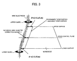
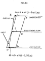
- FIG. 3 schematically shows an example of mathematical operations performed in the electric discharge machine according to the present invention to determine the wire-diameter correction amounts for an upper surface of the workpiece as the first plane and a lower surface of the workpiece as the second plane.
- a reference wire correction amount to be set in advance is determined as d.
- the reference wire correction amount d is a proper value for a wire-diameter correction amount for the speed control plane.
- the reference wire-diameter correction amount d is adjusted for the upper and lower surfaces of the workpiece.
- An adjustment amount for the upper surface is determined to be proportional to (1-Lu/Lm) and an adjustment amount for the lower surface is determined to be proportional to (1-LI/Lm).
- Lu, Lm and Ll are a machining distance at the upper surface, a machining distance on the speed control plane and a machining distance at the lower surface, respectively. Since, as a proportionality coefficient, a reference adjustment amount e is set in advance, the adjustment amounts are e(1-Lu/Lm) and e(1-Lu/Lm). Accordingly, the wire-diameter correction amount for the upper surface of the workpiece is d+e(1-Lu/Lm), while the wire-diameter correction amount for the lower surface of the workpiece is d+e(1-L1/Lm).
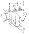
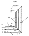
- reference sign 1 denotes a workpiece setting table for setting and fixing a workpiece 3 to be machined, which has an upward-facing setting surface 2 flat to a high accuracy. In machining, the workpiece 3 is set and fixed on the workpiece setting table with its bottom face in contact with the setting surface 2.
- the entire top face (upper surface) 31 is parallel to the bottom face (lower surface) 32.
- a workpiece 3 in the shape of a cuboid is exemplified, so that the entire top face 31 is parallel to the bottom face 32.
- the workpiece 3 can however be such that only part of the top face is parallel to the bottom face.
- Reference sign 4 denotes a wire electrode fed from a wire-electrode feed reel 5 via a power supply roller 6, an upper wire guide 7, etc. for performing electric discharge machining on the workpiece 3. In machining, the wire electrode is stretched between the upper and lower guides by wire connection operation, and a voltage is applied from an electric discharge power source 10 to produce electric discharge between the wire electrode and the workpiece 3.
- the wire electrode 4 is further pulled by a specified pulling force and wound onto a collection reel via a lower guide 8, a guide roller, etc.
- the wire electrode may be collected into a wire collection box instead of being wound onto a collection reel.
- machining fluid such as pouring machining fluid onto a machining location or immersing the whole workpiece 3 in a machining fluid (pure water, for example) is adopted.
- the setting surface 2 of the workpiece setting table 1 extends horizontally (on a plane parallel to the XY plane), and the workpiece setting table 1 can be driven by servo motors for the X and Y axes to move on a plane parallel to the XY plane.
- the upper wire guide can be driven by servo motors for the U and V axes to move on a plane parallel to the XY plane and driven by a servo motor for the Z axis to move perpendicular to the XY plane.
- the direction of movement by the U axis and the direction of movement by the X axis are parallel, while the direction of movement by the V axis and the direction of movement by the Y axis are parallel.
- the machining location can be changed by changing the relative position between the workpiece 3 and the wire electrode 4.
- the direction of the machining cross-sectional plane can be changed by changing the direction in which the wire electrode 4 is stretched.
- These changes can be achieved by combining the movements of the X, Y, U, V and Z axes appropriately.
- the movements of these axes are effected by commands for the axes (X axis command, Y axis command, U axis command, V axis command, Z axis command) fed from a numerical controller.
- the contents of the commands are defined according to a machining program (hereinafter referred to also simply as "program").
- the upper and lower wire guides are arranged at horizontally different positions to stretch the wire electrode 4 at an angle to the Z axis direction.
- the horizontal cross-sectional shape of the workpiece differs depending on the height.
- non-congruent shapes will be called “different shapes”.
- the shapes which are similar but different in size will be called “different shapes”.
- a horizontal plane intended to produce a cross-sectional shape identical to the shape designated by the machining program will be called a program plane
- another horizontal cross-sectional plane apart from the program plane by a distance corresponding to the thickness of the workpiece will be called an auxiliary plane.
- a taper machining plane where the wire electrode operates on the workpiece is defined between the program plane and the auxiliary plane.
- the height of the program plane is given by J relative to the workpiece setting table on which the workpiece is set.
- the distance (with a plus or minus sign) from the height of the program plane to the auxiliary plane is given by I.
- I and J may be directly fed according to the machining program, or entered through an MDI (external input device) prior to machining.
- MDI internal input device
- the upward direction (+Z direction) is considered plus.
- I By feeding zero as I, it is possible to set the program and auxiliary planes at the lower and upper surfaces, respectively.
- a negative value as I By feeding a negative value as I, it is possible to set the program and auxiliary planes at the upper and lower surfaces, respectively.
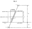
- FIG. 6 shows, in a vertical cross section, an example in which I ⁇ 0 and J>0, where the program plane is located between the workpiece upper and lower surfaces and the auxiliary plane is set at the lower surface.
- H, K and T represent the following amounts:
- the program plane is set at a certain height of the workpiece as shown in FIG. 6.
- the workpiece upper and lower surfaces do not serve directly as the program and auxiliary planes.
- explanation will be given with the program and auxiliary planes fixed at the workpiece lower and upper surfaces, respectively, as shown in FIG. 5.
- an electric-discharge-machining power source determines the machining speed on the basis of the state of electric discharge, where since the machining speed is different on the workpiece upper surface and on the workpiece lower surface (as explained later in detail), it is necessary to specify a horizontal plane at which the machining speed is controlled to be a designated speed (speed control plane).
- speed control plane There are cases in which machining is performed by designating the height of the speed control plane directly.
- the speed control plane is an intermediate plane between the program and auxiliary planes at which the machining speed is a mean.
- a first programming method is a method in which the shape of the workpiece lower surface, the direction of inclination of the taper surface, and the taper angle are designated. On the basis of the designated direction of inclination and taper angle, the machining shape on the workpiece upper surface is calculated, and the upper and lower wire guides are drive-controlled. Generally, similar machining shapes are obtained on the workpiece upper surface and on the workpiece lower surface.
- the direction of inclination of the taper surface the right inclination (represented by code G51) or the left inclination (represented by code G52) relative to the direction of progress of machining can be designated.
- FIG. 7a shows, in a top plan (viewed from the +Z direction), an example of a machining shape obtained by this programming method.
- FIG. 7b exemplifies the command contents corresponding to the machining shape shown in FIG. 7a.
- a second programming method is also called a different-upper-and-lower-shapes machining program. It is a method in which the shape of the workpiece upper surface as well as the shape of the workpiece lower surface is designated directly.
- deviation vectors relating to the workpiece upper and lower surfaces are defined, which makes the program complicated but makes it possible to define a taper surface that cannot be represented simply by an inclination angle.
- this method is used in special taper machining.
- FIG. 8a shows, in a top plan (viewed from the +Z direction), an example of a machining shape obtained by this programming method.
- FIG. 8b exemplifies the command contents corresponding to the machining shape shown in FIG. 8a. Arrows in broken line in FIG. 8a are deviation vectors relating to the workpiece upper and lower surfaces.
- the wire-diameter correction (correction for rectifying a machining shape error due to the wire diameter and the electric discharge gap).
- the proper wire-diameter correction amount on the workpiece upper surface is not the same as that on the workpiece lower surface.
- the shape on the workpiece upper surface needs to be calculated.
- deviation vectors are directly defined in each block.
- FIG. 9 is a diagram for explaining this addition and subtraction, where signs A1, A2, A3 exemplify three points representing a machining shape on the workpiece lower surface, and B1, B2, B3 exemplify three points corresponding to the above three points and representing a machining shape on the workpiece upper surface, where A2 and B2 are corner points.
- shape B2, B3 shape A ⁇ 2 , A ⁇ 3 + U ⁇ 3 , V ⁇ 3 - ( U ⁇ 2 , V ⁇ 2 )
- (U2, V2) is a deviation vector given for points A2, B2, and (U3, V3) is a deviation vector given for points A3, B3.
- the shape on the workpiece upper surface needs to be calculated on the basis of the shape on the workpiece lower surface, direction of inclination, and taper angle defined in the program.
- FIG. 10 is a diagram for explaining this calculation.
- signs A1, A2, A3 exemplify three points representing a machining shape on the workpiece lower surface
- B1, B2, B3 exemplify three points corresponding to the above three points and representing a machining shape on the workpiece upper surface, where A2 and B2 are corner points.
- the shape B1, B2, B3,... on the workpiece upper surface results from offsetting the shape A1, A2, A3,... on the workpiece lower surface by an amount I ⁇ TAN(T) to the left relative to the direction of machining progress (G52 represents the left inclination relative to the direction of machining progress), and can be easily obtained by a known offset calculation.
- the shape C1, C2, C3,... on the speed control plane (see FIGS. 9 and 10) is obtained as a set of points midway between the workpiece lower surface and the workpiece upper surface.
- the shape on the speed control plane can be obtained through proportional distribution.
- the machining distance L1 on the workpiece lower surface, the machining distance Lu on the workpiece upper surface, and the machining distance Lm on the speed control plane in each block of the machining program can be obtained easily.
- the shape A1, A2, A3,... on the workpiece lower surface and the shape B1, B2, B3,... on the workpiece upper surface can be produced by offsetting the machining path by the wire-diameter correction amount, i.e., the sum of the wire radius and the electric discharge gap amount, to the right relative to the direction of machining progress (G42 is a code representing an offset to the right relative to the direction of machining progress) and carrying out electric discharge machining by moving the wire electrode along the machining path thus offset.
- the wire-diameter correction amount i.e., the sum of the wire radius and the electric discharge gap amount
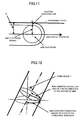
- the wire-diameter correction amount As a method of determining the wire-diameter correction amount, there is a method in which the workpiece machined into a taper shape is actually measured to obtain a value corresponding to the electric discharge gap amount + wire diameter (wire electrode radius) as the wire-diameter correction amount D, as shown in FIG. 11. There is also another method in which the wire-diameter correction amount in vertical machining divided by the cosine for the taper angle is used as a wire-diameter correction amount D in taper machining, as shown in FIG. 12.
- the same wire-diameter correction amount was used for the workpiece upper surface and the workpiece lower surface, which was a cause of decrease in accuracy of taper machining.
- the taper machining accuracy in actual taper machining is increased by using different wire-diameter correction amounts for the workpiece upper surface and the workpiece lower surface.
- the interpolation for a movement path in each block of the machining program needs to be started on the workpiece upper surface and the workpiece lower surface at the same time and finished at both faces at the same time.
- this difference in speed produces a difference in electric discharge gap amount.
- the electric discharge gap amount differs on the workpiece lower surface and on the workpiece upper surface, so that an uncut part remains at the plane where the speed is high and an over-cut is produced at the plane where the speed is low, so that the designated taper-angle face cannot be obtained. It can be thought that the amount of change in electric discharge gap is almost proportional to the frequency of electric discharge, and that the frequency of electric discharge is almost inversely proportional to the machining speed. Accordingly, by using, for the workpiece upper surface and workpiece lower surface, the wire-diameter correction amount decreased in proportion to the difference between the machining speed on the speed control plane and the machining speed at the workpiece upper or lower surface, the taper angle error due to the change in electric discharge gap can be corrected.
- the expressions show that the wire-diameter correction amount can be changed on the basis of the machining distance (Lu at the upper surface and L1 at the lower surface) in each block. Proper values for d and e can be obtained by an experiment such as a machining test.
- the proper values for d and e vary depending on the taper angle.
- a table storing values for d and e corresponding to taper angles consecutive with an appropriate interval is prepared in advance so that d and e values corresponding to an interpolated specified taper angle are obtained on the basis of the table.
- it can be arranged such that only d and e values for the wire electrode in vertical position are stored so that the d and e values divided by the cosine for a taper angle are used in taper machining.
- wire-diameter correction amounts for the workpiece upper surface and the workpiece lower surface are calculated, respectively. Then, as shown in FIG. 15, a shape D1, D2, D3, ... resulting from offsetting the shape A1, A2, A3, ... on the workpiece lower surface to the right relative to the direction of machining progress (G42 represents the right relative to the direction of machining progress) by the wire-diameter correction amount d1 (which differs depending on the block), and a shape E1, E2, E3, ... resulting from offsetting the shape B1, B2, B3, ... on the workpiece upper surface to the right relative to the direction of machining progress by the wire-diameter correction amount du (which differs depending on the block) are obtained.
- the movement paths calculated this way are those on the workpiece upper and lower surfaces.
- the actual movement of the wire electrode according to these movement paths is intended to be achieved through drive control on servo motors which drive the upper and lower wire guides.
- interpolation is required for the upper and lower wire guides so that the wire electrode moves, passing through D1, D2, D3, ... on the workpiece lower surface and passing through E1, E2, E3, ... on the workpiece upper surface.
- the interpolation calculation is performed in each interpolation cycle of a fixed period.
- machining speeds Fm are fed from the electric-discharge-machining power source, successively.
- the machining speeds are values with a sign. If a negative value is fed, so-called backward movement control is performed to cause a backward movement on the machining path to widen the electric discharge gap or remove a short circuit between the workpiece and the wire electrode. The details of the backward movement control will be omitted here.
- Ll, Lu, Lm represent distances according to the machining paths resulting from wire-diameter correction, which are more or less different from the machining distances before the wire-diameter correction, used in calculating wire-diameter correction amounts.
- the wire-diameter correction amounts should be calculated on the basis of the machining distances resulting from the wire-diameter correction.
- the machining distances resulting from the wire-diameter correction are unknown at the stage of calculating the wire-diameter correction amounts, and therefore, the wire-diameter correction amounts are calculated on the basis of the machining distances before the wire-diameter correction.
- the actual wire-diameter correction amount is a minute value of 0.5mm or smaller so that an error can be disregarded.
- movement amounts in the X and Y axis directions on the workpiece upper and lower surfaces can be obtained.
- the wire electrode speed on the speed control plane agrees with the machining speed Fm fed as a command from the electric-discharge-machining power source and taper machining can be performed with an accurate taper angle.
- the control can be performed by feeding differences between the movement amounts for the upper wire guide and the movement amounts for the lower wire guide, expressed by the equations below, to the servo motors for the U and V axes, respectively.
- Gux - Glx ⁇ Wux - ⁇ Wlx ⁇ H + K / I
- Guy - Gly ⁇ Wuy - ⁇ Wly ⁇ H + K / I
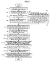
- the numerical controller (see FIG. 4) is only required to perform a procedure shown by the flow chart of FIG. 17, generate commands for the respective axes (X axis/Y axis, U axis/ V axis) as mentioned above, on the basis of this procedure and feed the generated commands to the servo control sections for the X axis/Y axis and the U axis/ V axis.
- the key points of the procedure shown by the flow chart of FIG. 17 have been already explained referring to FIG. 15, etc.
Landscapes
- Chemical & Material Sciences (AREA)
- Chemical Kinetics & Catalysis (AREA)
- Electrochemistry (AREA)
- Engineering & Computer Science (AREA)
- Mechanical Engineering (AREA)
- Electrical Discharge Machining, Electrochemical Machining, And Combined Machining (AREA)
Applications Claiming Priority (1)
| Application Number | Priority Date | Filing Date | Title |
|---|---|---|---|
| JP2005277840A JP4072548B2 (ja) | 2005-09-26 | 2005-09-26 | ワイヤ放電加工機 |
Publications (3)
| Publication Number | Publication Date |
|---|---|
| EP1769871A2 true EP1769871A2 (de) | 2007-04-04 |
| EP1769871A3 EP1769871A3 (de) | 2008-01-23 |
| EP1769871B1 EP1769871B1 (de) | 2010-08-18 |
Family
ID=37734303
Family Applications (1)
| Application Number | Title | Priority Date | Filing Date |
|---|---|---|---|
| EP06254939A Active EP1769871B1 (de) | 2005-09-26 | 2006-09-25 | Drahtschneidefunkenerosionsbearbeitungsmaschine |
Country Status (4)
| Country | Link |
|---|---|
| US (1) | US7371989B2 (de) |
| EP (1) | EP1769871B1 (de) |
| JP (1) | JP4072548B2 (de) |
| CN (1) | CN100506455C (de) |
Cited By (1)
| Publication number | Priority date | Publication date | Assignee | Title |
|---|---|---|---|---|
| EP2213400A1 (de) | 2009-01-29 | 2010-08-04 | Agie Charmilles SA | Verfahren und Vorrichtung für drahtschneidende elektrische Entladungsmaschine |
Families Citing this family (15)
| Publication number | Priority date | Publication date | Assignee | Title |
|---|---|---|---|---|
| PL2008736T3 (pl) * | 2007-06-30 | 2011-11-30 | Trumpf Werkzeugmaschinen Gmbh Co Kg | Obrabiarka i sposób wyrzucania części przedmiotu obrabianego |
| WO2011004426A1 (ja) * | 2009-07-07 | 2011-01-13 | 三菱電機株式会社 | ワイヤ放電加工装置 |
| JP5369205B2 (ja) * | 2012-02-27 | 2013-12-18 | ファナック株式会社 | 切込み加工時、逃げ加工時の加工傷を低減するワイヤ放電加工機およびワイヤ放電加工方法 |
| JP5722382B2 (ja) * | 2013-01-09 | 2015-05-20 | ファナック株式会社 | コーナ部で加工経路の補正を行うワイヤ放電加工機 |
| JP5642819B2 (ja) * | 2013-02-19 | 2014-12-17 | ファナック株式会社 | 接触検出器を使用したテーパ角度補正機能を有するワイヤ放電加工機およびテーパ角度補正方法 |
| JP5705907B2 (ja) * | 2013-04-15 | 2015-04-22 | ファナック株式会社 | テーパ加工を行うワイヤ放電加工機 |
| JP5752196B2 (ja) | 2013-09-03 | 2015-07-22 | ファナック株式会社 | ワイヤ放電加工機用のプログラム作成装置 |
| JP5850894B2 (ja) * | 2013-09-09 | 2016-02-03 | ファナック株式会社 | テーパ加工を行うワイヤ放電加工機を制御する数値制御装置 |
| JP5731613B2 (ja) | 2013-10-18 | 2015-06-10 | ファナック株式会社 | ワイヤ放電加工機およびワイヤ放電加工機の制御装置 |
| JP5800878B2 (ja) * | 2013-10-30 | 2015-10-28 | ファナック株式会社 | 放電加工機 |
| US9878386B2 (en) * | 2013-10-31 | 2018-01-30 | Foundation Of Soongsil University-Industry Cooperation | Eccentric electrode for electric discharge machining, method of manufacturing the same, and micro electric discharge machining apparatus including the same |
| WO2015145529A1 (ja) * | 2014-03-24 | 2015-10-01 | 三菱電機株式会社 | ワイヤ放電加工装置および加工方法 |
| EP3023186A1 (de) * | 2014-11-19 | 2016-05-25 | Fanuc Corporation | Drahterosionsmaschine mit funktion zum ausgleichen von eckfehlern |
| JP6247260B2 (ja) * | 2015-08-24 | 2017-12-13 | ファナック株式会社 | 様々な面の加工が可能なワイヤ放電加工機 |
| JP6490118B2 (ja) * | 2017-01-26 | 2019-03-27 | ファナック株式会社 | 数値制御装置 |
Citations (2)
| Publication number | Priority date | Publication date | Assignee | Title |
|---|---|---|---|---|
| EP0920944A2 (de) * | 1997-12-03 | 1999-06-09 | Fanuc Ltd | Vorrichtung zur Steuerung von Drahtfunkenerosionsprozessen mit Konusbearbeitungskorrekturfähigkeit |
| US20040084419A1 (en) * | 2002-10-24 | 2004-05-06 | Fanuc Ltd. | Wire electric discharge machine |
Family Cites Families (4)
| Publication number | Priority date | Publication date | Assignee | Title |
|---|---|---|---|---|
| JPS6056824A (ja) * | 1983-09-06 | 1985-04-02 | Fanuc Ltd | ワイヤ放電加工方法 |
| JPH08314518A (ja) * | 1995-05-15 | 1996-11-29 | Fanuc Ltd | ワイヤ径補正量指令方式 |
| JP2001269819A (ja) * | 2000-03-24 | 2001-10-02 | Brother Ind Ltd | ワイヤ放電加工機の制御装置及び制御方法 |
| TWI277846B (en) * | 2004-12-23 | 2007-04-01 | Ind Tech Res Inst | Method of 3D electric discharge machining and program generating apparatus therefor |
-
2005
- 2005-09-26 JP JP2005277840A patent/JP4072548B2/ja active Active
-
2006
- 2006-09-21 US US11/524,400 patent/US7371989B2/en active Active
- 2006-09-25 EP EP06254939A patent/EP1769871B1/de active Active
- 2006-09-26 CN CNB200610159935XA patent/CN100506455C/zh active Active
Patent Citations (2)
| Publication number | Priority date | Publication date | Assignee | Title |
|---|---|---|---|---|
| EP0920944A2 (de) * | 1997-12-03 | 1999-06-09 | Fanuc Ltd | Vorrichtung zur Steuerung von Drahtfunkenerosionsprozessen mit Konusbearbeitungskorrekturfähigkeit |
| US20040084419A1 (en) * | 2002-10-24 | 2004-05-06 | Fanuc Ltd. | Wire electric discharge machine |
Cited By (2)
| Publication number | Priority date | Publication date | Assignee | Title |
|---|---|---|---|---|
| EP2213400A1 (de) | 2009-01-29 | 2010-08-04 | Agie Charmilles SA | Verfahren und Vorrichtung für drahtschneidende elektrische Entladungsmaschine |
| US8242403B2 (en) | 2009-01-29 | 2012-08-14 | Agie Charmilles Sa | Wire electric discharge machining method and apparatus |
Also Published As
| Publication number | Publication date |
|---|---|
| EP1769871B1 (de) | 2010-08-18 |
| JP2007083372A (ja) | 2007-04-05 |
| CN100506455C (zh) | 2009-07-01 |
| JP4072548B2 (ja) | 2008-04-09 |
| US7371989B2 (en) | 2008-05-13 |
| EP1769871A3 (de) | 2008-01-23 |
| US20070068905A1 (en) | 2007-03-29 |
| CN1939631A (zh) | 2007-04-04 |
Similar Documents
| Publication | Publication Date | Title |
|---|---|---|
| EP1769871B1 (de) | Drahtschneidefunkenerosionsbearbeitungsmaschine | |
| US7211762B2 (en) | Wire electric discharge machine and wire electric discharge machining method | |
| US8829383B2 (en) | Wire electric discharge machine and wire electric discharge machining method | |
| WO2020026306A1 (ja) | 積層条件制御装置 | |
| EP2532464B1 (de) | Verfahren zum Betreiben einer Drahterodiermaschine zur Herstellung von Schrägen durch Neigen des Werkstücks | |
| EP0155323A1 (de) | Funkenerosionsverfahren des drahttyps | |
| JP4199103B2 (ja) | 数値制御装置及び数値制御方法 | |
| CN104570930B (zh) | 机床以及控制所述机床的数值控制装置 | |
| US5021622A (en) | Wire cut electrical discharge machine | |
| US8924004B2 (en) | Numerical controller for making positioning completion check | |
| EP2295180A2 (de) | Elektrisches Drahterodierverfahren, Vorrichtung dafür, Vorrichtung zur Erzeugung des Drahterodierprogramms und computerlesbares Aufzeichnungsmedium mit darauf gespeichertem Programm zur Erzeugung des Drahterodierprogramms | |
| US9442479B2 (en) | Wire electric discharge machine controller, wire electric discharge machine, and wire electric discharge machining method | |
| US20080201010A1 (en) | Punch machining program generating device, recording medium storing a program for generating a punch machining program, and wire-cut electric discharge machine | |
| US6972389B2 (en) | Method and apparatus for preparing program for die machining | |
| US10427231B2 (en) | Numerical controller | |
| CN112865750A (zh) | 基于fir滤波器的数控系统倍率变化平滑控制方法及装置 | |
| JPS594252B2 (ja) | テ−パ加工方法 | |
| JPS6351811B2 (de) | ||
| JP2000024839A (ja) | ワイヤ放電加工方法および装置 | |
| JPH0724645A (ja) | ワイヤ放電加工装置 | |
| CN110270726B (zh) | 线放电加工机 | |
| JPH04176516A (ja) | ワイヤ放電加工におけるセカンドカット加工方法及びセカンドカット加工制御装置 | |
| KR0168072B1 (ko) | 공구직경에 따른 이동경로 보정방법 | |
| JPS6351810B2 (de) | ||
| JPH10263933A (ja) | ワイヤ放電加工方法およびワイヤ放電加工装置 |
Legal Events
| Date | Code | Title | Description |
|---|---|---|---|
| PUAI | Public reference made under article 153(3) epc to a published international application that has entered the european phase |
Free format text: ORIGINAL CODE: 0009012 |
|
| AK | Designated contracting states |
Kind code of ref document: A2 Designated state(s): AT BE BG CH CY CZ DE DK EE ES FI FR GB GR HU IE IS IT LI LT LU LV MC NL PL PT RO SE SI SK TR |
|
| AX | Request for extension of the european patent |
Extension state: AL BA HR MK YU |
|
| PUAL | Search report despatched |
Free format text: ORIGINAL CODE: 0009013 |
|
| AK | Designated contracting states |
Kind code of ref document: A3 Designated state(s): AT BE BG CH CY CZ DE DK EE ES FI FR GB GR HU IE IS IT LI LT LU LV MC NL PL PT RO SE SI SK TR |
|
| AX | Request for extension of the european patent |
Extension state: AL BA HR MK YU |
|
| RIC1 | Information provided on ipc code assigned before grant |
Ipc: B23H 7/06 20060101AFI20070222BHEP Ipc: B23H 7/02 20060101ALI20071217BHEP |
|
| 17P | Request for examination filed |
Effective date: 20080328 |
|
| 17Q | First examination report despatched |
Effective date: 20080522 |
|
| AKX | Designation fees paid |
Designated state(s): CH LI |
|
| REG | Reference to a national code |
Ref country code: DE Ref legal event code: 8566 |
|
| GRAP | Despatch of communication of intention to grant a patent |
Free format text: ORIGINAL CODE: EPIDOSNIGR1 |
|
| GRAS | Grant fee paid |
Free format text: ORIGINAL CODE: EPIDOSNIGR3 |
|
| GRAA | (expected) grant |
Free format text: ORIGINAL CODE: 0009210 |
|
| AK | Designated contracting states |
Kind code of ref document: B1 Designated state(s): CH LI |
|
| REG | Reference to a national code |
Ref country code: CH Ref legal event code: EP |
|
| REG | Reference to a national code |
Ref country code: CH Ref legal event code: NV Representative=s name: R. A. EGLI & CO. PATENTANWAELTE |
|
| RAP2 | Party data changed (patent owner data changed or rights of a patent transferred) |
Owner name: FANUC CORPORATION |
|
| PLBE | No opposition filed within time limit |
Free format text: ORIGINAL CODE: 0009261 |
|
| STAA | Information on the status of an ep patent application or granted ep patent |
Free format text: STATUS: NO OPPOSITION FILED WITHIN TIME LIMIT |
|
| 26N | No opposition filed |
Effective date: 20110519 |
|
| PGFP | Annual fee paid to national office [announced via postgrant information from national office to epo] |
Ref country code: CH Payment date: 20231001 Year of fee payment: 18 |