EP1769152B1 - Control apparatus for internal combustion engine - Google Patents
Control apparatus for internal combustion engine Download PDFInfo
- Publication number
- EP1769152B1 EP1769152B1 EP05767330A EP05767330A EP1769152B1 EP 1769152 B1 EP1769152 B1 EP 1769152B1 EP 05767330 A EP05767330 A EP 05767330A EP 05767330 A EP05767330 A EP 05767330A EP 1769152 B1 EP1769152 B1 EP 1769152B1
- Authority
- EP
- European Patent Office
- Prior art keywords
- fuel injection
- internal combustion
- combustion engine
- engine
- fuel
- Prior art date
- Legal status (The legal status is an assumption and is not a legal conclusion. Google has not performed a legal analysis and makes no representation as to the accuracy of the status listed.)
- Ceased
Links
- 238000002485 combustion reaction Methods 0.000 title claims description 164
- 239000000446 fuel Substances 0.000 claims abstract description 229
- 238000002347 injection Methods 0.000 claims abstract description 150
- 239000007924 injection Substances 0.000 claims abstract description 150
- 230000007246 mechanism Effects 0.000 claims description 37
- 239000003054 catalyst Substances 0.000 claims description 23
- 230000002159 abnormal effect Effects 0.000 claims description 7
- 230000008859 change Effects 0.000 claims description 2
- 238000001514 detection method Methods 0.000 claims description 2
- 239000002826 coolant Substances 0.000 abstract description 12
- 239000000203 mixture Substances 0.000 description 18
- 230000006835 compression Effects 0.000 description 10
- 238000007906 compression Methods 0.000 description 10
- 230000002349 favourable effect Effects 0.000 description 5
- 238000009825 accumulation Methods 0.000 description 3
- 230000000694 effects Effects 0.000 description 3
- 238000000034 method Methods 0.000 description 3
- 230000008901 benefit Effects 0.000 description 2
- 230000003197 catalytic effect Effects 0.000 description 2
- 239000000567 combustion gas Substances 0.000 description 2
- 238000010586 diagram Methods 0.000 description 2
- 239000002828 fuel tank Substances 0.000 description 2
- 239000007789 gas Substances 0.000 description 2
- 230000008569 process Effects 0.000 description 2
- 238000010792 warming Methods 0.000 description 2
- QVGXLLKOCUKJST-UHFFFAOYSA-N atomic oxygen Chemical compound [O] QVGXLLKOCUKJST-UHFFFAOYSA-N 0.000 description 1
- 238000000889 atomisation Methods 0.000 description 1
- 230000002457 bidirectional effect Effects 0.000 description 1
- 238000001816 cooling Methods 0.000 description 1
- 230000007423 decrease Effects 0.000 description 1
- 230000003247 decreasing effect Effects 0.000 description 1
- 230000009977 dual effect Effects 0.000 description 1
- 230000006870 function Effects 0.000 description 1
- 239000003502 gasoline Substances 0.000 description 1
- 230000006872 improvement Effects 0.000 description 1
- 238000007562 laser obscuration time method Methods 0.000 description 1
- 238000012986 modification Methods 0.000 description 1
- 230000004048 modification Effects 0.000 description 1
- 239000001301 oxygen Substances 0.000 description 1
- 229910052760 oxygen Inorganic materials 0.000 description 1
- 230000035515 penetration Effects 0.000 description 1
- 238000000746 purification Methods 0.000 description 1
- 239000000243 solution Substances 0.000 description 1
- 230000000087 stabilizing effect Effects 0.000 description 1
- 238000011144 upstream manufacturing Methods 0.000 description 1
- 238000009834 vaporization Methods 0.000 description 1
- 230000008016 vaporization Effects 0.000 description 1
Images


Classifications
-
- F—MECHANICAL ENGINEERING; LIGHTING; HEATING; WEAPONS; BLASTING
- F02—COMBUSTION ENGINES; HOT-GAS OR COMBUSTION-PRODUCT ENGINE PLANTS
- F02D—CONTROLLING COMBUSTION ENGINES
- F02D41/00—Electrical control of supply of combustible mixture or its constituents
- F02D41/30—Controlling fuel injection
-
- F—MECHANICAL ENGINEERING; LIGHTING; HEATING; WEAPONS; BLASTING
- F02—COMBUSTION ENGINES; HOT-GAS OR COMBUSTION-PRODUCT ENGINE PLANTS
- F02D—CONTROLLING COMBUSTION ENGINES
- F02D41/00—Electrical control of supply of combustible mixture or its constituents
- F02D41/30—Controlling fuel injection
- F02D41/3011—Controlling fuel injection according to or using specific or several modes of combustion
- F02D41/3076—Controlling fuel injection according to or using specific or several modes of combustion with special conditions for selecting a mode of combustion, e.g. for starting, for diagnosing
-
- F—MECHANICAL ENGINEERING; LIGHTING; HEATING; WEAPONS; BLASTING
- F02—COMBUSTION ENGINES; HOT-GAS OR COMBUSTION-PRODUCT ENGINE PLANTS
- F02B—INTERNAL-COMBUSTION PISTON ENGINES; COMBUSTION ENGINES IN GENERAL
- F02B17/00—Engines characterised by means for effecting stratification of charge in cylinders
-
- F—MECHANICAL ENGINEERING; LIGHTING; HEATING; WEAPONS; BLASTING
- F02—COMBUSTION ENGINES; HOT-GAS OR COMBUSTION-PRODUCT ENGINE PLANTS
- F02D—CONTROLLING COMBUSTION ENGINES
- F02D41/00—Electrical control of supply of combustible mixture or its constituents
- F02D41/02—Circuit arrangements for generating control signals
- F02D41/04—Introducing corrections for particular operating conditions
- F02D41/06—Introducing corrections for particular operating conditions for engine starting or warming up
- F02D41/062—Introducing corrections for particular operating conditions for engine starting or warming up for starting
- F02D41/064—Introducing corrections for particular operating conditions for engine starting or warming up for starting at cold start
-
- F—MECHANICAL ENGINEERING; LIGHTING; HEATING; WEAPONS; BLASTING
- F02—COMBUSTION ENGINES; HOT-GAS OR COMBUSTION-PRODUCT ENGINE PLANTS
- F02D—CONTROLLING COMBUSTION ENGINES
- F02D41/00—Electrical control of supply of combustible mixture or its constituents
- F02D41/30—Controlling fuel injection
- F02D41/3094—Controlling fuel injection the fuel injection being effected by at least two different injectors, e.g. one in the intake manifold and one in the cylinder
-
- F—MECHANICAL ENGINEERING; LIGHTING; HEATING; WEAPONS; BLASTING
- F02—COMBUSTION ENGINES; HOT-GAS OR COMBUSTION-PRODUCT ENGINE PLANTS
- F02M—SUPPLYING COMBUSTION ENGINES IN GENERAL WITH COMBUSTIBLE MIXTURES OR CONSTITUENTS THEREOF
- F02M63/00—Other fuel-injection apparatus having pertinent characteristics not provided for in groups F02M39/00 - F02M57/00 or F02M67/00; Details, component parts, or accessories of fuel-injection apparatus, not provided for in, or of interest apart from, the apparatus of groups F02M39/00 - F02M61/00 or F02M67/00; Combination of fuel pump with other devices, e.g. lubricating oil pump
- F02M63/02—Fuel-injection apparatus having several injectors fed by a common pumping element, or having several pumping elements feeding a common injector; Fuel-injection apparatus having provisions for cutting-out pumps, pumping elements, or injectors; Fuel-injection apparatus having provisions for variably interconnecting pumping elements and injectors alternatively
- F02M63/0225—Fuel-injection apparatus having a common rail feeding several injectors ; Means for varying pressure in common rails; Pumps feeding common rails
- F02M63/0275—Arrangement of common rails
- F02M63/0285—Arrangement of common rails having more than one common rail
- F02M63/029—Arrangement of common rails having more than one common rail per cylinder bank, e.g. storing different fuels or fuels at different pressure levels per cylinder bank
Definitions
- the present invention relates to a control apparatus for an internal combustion engine having first fuel injection means (an in-cylinder injector) for injecting a fuel into a cylinder and second fuel injection means (an intake manifold injector) for injecting a fuel into an intake manifold or an intake port, and relates particularly to a technique for determining a fuel injection ratio between the first and second fuel injection means.
- first fuel injection means an in-cylinder injector
- second fuel injection means an intake manifold injector
- An internal combustion engine having a first fuel injection valve (an intake manifold injector in the background art) for injecting a fuel into an intake manifold of the engine and a second fuel injection valve (an in-cylinder injector in the background art) for always injecting a fuel into a combustion chamber of the engine, and configured to stop fuel injection from the first fuel injection valve (the intake manifold injector) when the engine load is lower than a preset load and to cause fuel injection from the first fuel injection valve (the intake manifold injector) when the engine load is higher than the set load, is known.
- one configured to switch between stratified charge combustion and homogeneous combustion in accordance with its operation state is known.
- the fuel is injected from the in-cylinder injector during a compression stroke to form a stratified air-fuel mixture locally around a spark plug, for lean combustion of the fuel.
- the fuel is diffused in the combustion chamber to form a homogeneous air-fuel mixture, for combustion of the fuel.
- Japanese Patent Laying-Open No. 2001-020837 or EP 0849455 disclose a fuel injection control apparatus for an engine that switches between stratified charge combustion and homogeneous combustion in accordance with an operation state and that has a main fuel injection valve for injecting a fuel directly into a combustion chamber and a secondary fuel injection valve for injecting a fuel into an intake port of each cylinder.
- This fuel injection control apparatus for the engine is characterized in that the fuel injection ratio between the main fuel injection valve and the secondary fuel injection valve is set in a variable manner based on an operation state of the engine.
- the stratified charge combustion is carried out using only the main fuel injection valve directly injecting the fuel into the combustion chamber, while the homogeneous combustion is carried out using both the main fuel injection valve and the secondary fuel injection valve (or using only the secondary fuel injection valve in some cases).
- This can keep the capacity of the main fuel injection valve small, even in the case of an engine of high power.
- Linearity in injection duration/injection quantity characteristic of the main fuel injection valve in a low-load region such as during idling is improved, which in turn improves accuracy in control of the fuel injection quantity. Accordingly, it is possible to maintain favorable stratified charge combustion, and thus to improve stability of the low-load operation such as idling.
- both the main and secondary fuel injection valves are employed, so that the benefit of the direct fuel injection and the benefit of the intake port injection are both enjoyed. Accordingly, favorable homogeneous combustion can also be maintained.
- the stratified charge combustion and the homogeneous combustion are employed according to the situations, which complicates ignition control, injection control and throttle control, and requires control programs corresponding to the respective combustion manners. Particularly, upon switching between the combustion manners, these controls require considerable changes, making it difficult to realize desirable controls (of fuel efficiency, emission purification performance) at the time of transition. Further, in the stratified combustion region where lean combustion is carried out, the three-way catalyst does not work, in which case a lean NOx catalyst needs to be used, leading to an increased cost.
- a direct injection engine which has only an in-cylinder injector to carry out homogeneous combustion over the entire region, with no stratified charge combustion conducted, and thus does not need control for switching between the stratified charge combustion and the homogeneous combustion and does not require an expensive lean NOx catalyst.
- An object of the present invention is to provide a control apparatus for an internal combustion engine conducting fuel injection using one or both of a first fuel injection mechanism for injecting a fuel into a cylinder and a second fuel injection mechanism for injecting a fuel into an intake manifold, capable of solving the problem associated with a combination of stratified charge combustion and homogeneous combustion, and also capable of solving the problem associated with homogeneous combustion in the case of a direct injection engine.
- a control apparatus controls an internal combustion engine having a first fuel injection mechanism for injecting a fuel into a cylinder and a second fuel injection mechanism for injecting a fuel into an intake manifold.
- the control apparatus includes a determination unit for determining whether the internal combustion engine is in a normal operation state, and a control unit for controlling the first and second fuel injection mechanisms based on information associated with an operation state of the internal combustion engine such that homogeneous combustion solely is carried out when it is determined that the internal combustion engine is in the normal operation state.
- the fuel injection ratio between the in-cylinder injector and the intake manifold injector is controlled based on an operation state of the internal combustion engine (determined, e.g., by the engine speed and the load thereof) that is set separately for the warm state and the cold state of the internal combustion engine, for example.
- an operation state other than the normal operation state is a catalyst warm-up operation during idling.
- the information is set such that control regions of the first and second fuel injection mechanisms change as a temperature of the internal combustion engine changes.
- the control apparatus further includes a detection unit for detecting the temperature of the internal combustion engine, and the control unit controls the fuel injection mechanisms based on the detected temperature and the information.
- the fuel injection ratio between the in-cylinder injector and the intake manifold injector is set based on the temperature of the internal combustion engine (separately for the warm state and the cold state of the internal combustion engine, for example), or the fuel injection ratio therebetween is set using the temperature of the internal combustion engine as a parameter.
- the regions of the fuel supply injectors of different characteristics variable in accordance with the temperature of the internal combustion engine it is possible to provide a control apparatus for an internal combustion engine of high performance having dual injectors.
- the information is set such that the control region of the second fuel injection mechanism is expanded to include a region of higher engine speed as the temperature of the internal combustion engine is lower.
- accumulation of deposits in the in-cylinder injector is further restricted as the temperature of the internal combustion engine is lower. It is thus possible to secure a large injection region for the intake manifold injector (including the region where both the intake manifold injector and the in-cylinder injector are used), which can improve homogeneity of the air-fuel mixture.
- the information is set such that the first fuel injection mechanism alone is used in a predetermined, high engine speed region. More preferably, the information is set such that the first fuel injection mechanism alone is used in a predetermined, high engine load region.
- the determination unit determines that the internal combustion engine is in an abnormal operation state during a catalyst warm-up operation upon idling. Then, the control unit controls the first fuel injection mechanism to carry out stratified charge combustion in the abnormal operation state.
- the stratified charge combustion includes both the stratified charge combustion and semi-stratified charge combustion.
- an intake manifold injector injects fuel in the intake stroke to generate a lean and homogeneous air-fuel mixture in the whole combustion chamber, and then an in-cylinder injector injects fuel in the compression stroke to generate a rich air-fuel mixture around the spark plug, so as to improve the combustion state.
- Such semi-stratified charge combustion is preferable in the catalyst warm-up operation for the following reasons. In the catalyst warm-up operation, it is necessary to considerably retard the ignition timing and maintain a good combustion state (idling state) so as to cause a high-temperature combustion gas to reach the catalyst. Further, a certain quantity of fuel needs to be supplied.
- the quantity of the fuel will be insufficient.
- the retarded amount for the purpose of maintaining a good combustion state is small compared to the case of stratified charge combustion.
- the above-described semi-stratified charge combustion is preferably employed in the catalyst warm-up operation, although either of stratified charge combustion and semi-stratified charge combustion may be employed.
- the information is set such that the first fuel injection mechanism alone is used in a predetermined, low engine load region when a temperature of the internal combustion engine is high.
- the temperature at the injection hole of the in-cylinder injector is high, and deposits are likely to accumulate in the injection hole. According to the invention, however, injecting the fuel using the in-cylinder injector can lower the temperature at the injection hole, thereby preventing accumulation of the deposits therein. Further, the minimum fuel injection quantity of the in-cylinder injection can be guaranteed while preventing clogging of the in-cylinder injector. Accordingly, homogeneous combustion is realized in the relevant region using the in-cylinder injector.
- the information is set such that the second fuel injection mechanism alone is used in a predetermined, low engine load region when the temperature of the internal combustion engine is low.
- the intake manifold injector solely is used for fuel injection in the relevant region, which can improve the homogeneity of the air-fuel mixture.
- the information includes information indicating a fuel injection ratio between the first and second fuel injection mechanisms that is defied by the engine speed and the load factor of the internal combustion engine.
- the fuel injection ratio between the in-cylinder injector and the intake manifold injector is determined based on the engine speed and the load factor of the internal combustion engine, and in a normal operation state, homogeneous combustion is realized with any engine speed and any load factor.
- the first fuel injection mechanism is an in-cylinder injector
- the second fuel injection mechanism is an intake manifold injector
- control apparatus for the internal combustion engine in which fuel injection is carried out using the in-cylinder injector as the first fuel injection mechanism and the intake manifold injector as the second fuel injection mechanism that are separately provided, capable of solving the problem associated with the combination of the stratified charge combustion and the homogeneous combustion as well as the problem associated with the homogeneous combustion in the case of a direct injection engine.
- Fig. 1 is a schematic configuration diagram of an engine system that is controlled by an engine ECU (Electronic Control Unit) implementing the control apparatus for an internal combustion engine according to an embodiment of the present invention.
- ECU Electronic Control Unit
- Fig. 1 an in-line 4-cylinder gasoline engine is shown, although the application of the present invention is not restricted to such an engine.
- the engine 10 includes four cylinders 112, each connected via a corresponding intake manifold 20 to a common surge tank 30.
- Surge tank 30 is connected via an intake duct 40 to an air cleaner 50.
- An airflow meter 42 is arranged in intake duct 40, and a throttle valve 70 driven by an electric motor 60 is also arranged in intake duct 40.
- Throttle valve 70 has its degree of opening controlled based on an output signal of an engine ECU 300, independently from an accelerator pedal 100.
- Each cylinder 112 is connected to a common exhaust manifold 80, which is connected to a three-way catalytic converter 90.
- Each cylinder 112 is provided with an in-cylinder injector 110 for injecting fuel into the cylinder and an intake manifold injector 120 for injecting fuel into an intake port or/and an intake manifold. Injectors 110 and 120 are controlled based on output signals from engine ECU 300. Further, in-cylinder injector 110 of each cylinder is connected to a common fuel delivery pipe 130. Fuel delivery pipe 130 is connected to a high-pressure fuel pump 150 of an engine-driven type, via a check valve 140 that allows a flow in the direction toward fuel delivery pipe 130.
- an internal combustion engine having two injectors separately provided is explained, although the present invention is not restricted to such an internal combustion engine.
- the internal combustion engine may have one injector that can effect both in-cylinder injection and intake manifold injection.
- Electromagnetic spill valve 152 is controlled based on an output signal of engine ECU 300.
- Each intake manifold injector 120 is connected to a common fuel delivery pipe 160 on a low pressure side.
- Fuel delivery pipe 160 and high-pressure fuel pump 150 are connected via a common fuel pressure regulator 170 to a low-pressure fuel pump 180 of an electric motor-driven type.
- low-pressure fuel pump 180 is connected via a fuel filter 190 to a fuel tank 200.
- Fuel pressure regulator 170 is configured to return a part of the fuel discharged from low-pressure fuel pump 180 back to fuel tank 200 when the pressure of the fuel discharged from low-pressure fuel pump 180 is higher than a preset fuel pressure. This prevents both the pressure of the fuel supplied to intake manifold injector 120 and the pressure of the fuel supplied to high-pressure fuel pump 150 from becoming higher than the above-described preset fuel pressure.
- Engine ECU 300 is implemented with a digital computer, and includes a ROM (Read Only Memory) 320, a RAM (Random Access Memory) 330, a CPU (Central Processing Unit) 340, an input port 350, and an output port 360, which are connected to each other via a bidirectional bus 310.
- ROM Read Only Memory
- RAM Random Access Memory
- CPU Central Processing Unit
- Airflow meter 42 generates an output voltage that is proportional to an intake air quantity, and the output voltage is input via an A/D converter 370 to input port 350.
- a coolant temperature sensor 380 is attached to engine 10, and generates an output voltage proportional to a coolant temperature of the engine, which is input via an A/D converter 390 to input port 350.
- a fuel pressure sensor 400 is attached to fuel delivery pipe 130, and generates an output voltage proportional to a fuel pressure within fuel delivery pipe 130, which is input via an A/D converter 410 to input port 350.
- An air-fuel ratio sensor 420 is attached to an exhaust manifold 80 located upstream of three-way catalytic converter 90. Air-fuel ratio sensor 420 generates an output voltage proportional to an oxygen concentration within the exhaust gas, which is input via an A/D converter 430 to input port 350.
- Air-fuel ratio sensor 420 of the engine system of the present embodiment is a full-range air-fuel ratio sensor (linear air-fuel ratio sensor) that generates an output voltage proportional to the air-fuel ratio of the air-fuel mixture burned in engine 10.
- an O 2 sensor may be employed, which detects, in an on/off manner, whether the air-fuel ratio of the air-fuel mixture burned in engine 10 is rich or lean with respect to a theoretical air-fuel ratio.
- Accelerator pedal 100 is connected with an accelerator press-down degree sensor 440 that generates an output voltage proportional to the degree of press down of accelerator pedal 100, which is input via an A/D converter 450 to input port 350. Further, an engine speed sensor 460 generating an output pulse representing the engine speed is connected to input port 350.
- ROM 320 of engine ECU 300 prestores, in the form of a map, values of fuel injection quantity that are set in association with operation states based on the engine load factor and the engine speed obtained by the above-described accelerator press-down degree sensor 440 and engine speed sensor 460, and correction values thereof set based on the engine coolant temperature.
- Figs. 2 and 3 maps each indicating a fuel injection ratio between in-cylinder injector 110 and intake manifold injector 120, identified as information associated with an operation state of engine 10, will now be described.
- the fuel injection ratio between the two injectors will also be expressed as a ratio of the quantity of the fuel injected from in-cylinder injector 110 to the total quantity of the fuel injected, which is referred to as the "fuel injection ratio of in-cylinder injector 110", or, a "DI (Direct Injection) ratio (r)”.
- the maps are stored in ROM 320 of engine ECU 300.
- Fig. 2 shows the map for the warm state of engine 10
- Fig. 3 shows the map for the cold state of engine 10.
- the fuel injection ratio of in-cylinder injector 110, or the DI ratio r is expressed in percentage.
- the DI ratio r is set for each operation region that is determined by the engine speed and the load factor of engine 10.
- "DI RATIO r ⁇ 0%”, “DI RATIO r ⁇ 100%” and "0% ⁇ DI RATIO r ⁇ 100%” each represent the region where fuel injection is carried out using both in-cylinder injector 110 and intake manifold injector 120.
- in-cylinder injector 110 contributes to an increase of output performance
- intake manifold injector 120 contributes to uniformity of the air-fuel mixture.
- the fuel injection ratio between in-cylinder injector 110 and intake manifold injector 120 is defined as the DI ratio r, individually in the maps for the warm state and the cold state of the engine.
- the maps are configured to indicate different control regions of in-cylinder injector 110 and intake manifold injector 120 as the temperature of engine 10 changes.
- the map for the warm state shown in Fig. 2 is selected; otherwise, the map for the cold state shown in Fig. 3 is selected.
- One or both of in-cylinder injector 110 and intake manifold injector 120 are controlled based on the selected map and according to the engine speed and the load factor of engine 10 (which corresponds to claim 2).
- NE(1) is set to 2500 rpm to 2700 rpm
- KL(1) is set to 30% to 50%
- KL(2) is set to 60% to 90%
- NE(3) is set to 2900 rpm to 3100 rpm. That is, NE(1) ⁇ NE(3).
- NE(2) in Fig. 2 as well as KL(3) and KL(4) in Fig. 3 are also set as appropriate.
- NE(3) of the map for the cold state shown in Fig. 3 is greater than NE(1) of the map for the warm state shown in Fig. 2 .
- the control region of intake manifold injector 120 is expanded to include the region of higher engine speed (which corresponds to claim 3). That is, when engine 10 is cold, deposits are unlikely to accumulate in the injection hole of in-cylinder injector 110 (even if the fuel is not injected from in-cylinder injector 110).
- the region where the fuel injection is to be carried out using intake manifold injector 120 can be expanded, to thereby improve homogeneity.
- the engine speed and the load of engine 10 are high, ensuring a sufficient intake air quantity, so that it is readily possible to obtain a homogeneous air-fuel mixture even using only in-cylinder injector 110.
- the fuel injected from in-cylinder injector 110 is atomized within the combustion chamber involving latent heat of vaporization (or, absorbing heat from the combustion chamber). This decreases the temperature of the air-fuel mixture at the compression end, so that the antiknock performance is improved. Further, since the temperature in the combustion chamber is decreased, intake efficiency improves, ensuring high power.
- in-cylinder injector 110 In the map for the warm state in Fig. 2 , fuel injection is also carried out using only in-cylinder injector 110 when the load factor is KL(1) or less. This shows that in-cylinder injector 110 solely is used in a predetermined, low engine load region when the temperature of engine 10 is high (which corresponds to claim 7). When engine 10 is in the warm state, deposits are likely to accumulate in the injection hole of in-cylinder injector 110. However, when fuel injection is carried out using in-cylinder injector 110, the temperature of the injection hole can be lowered, which may prevent accumulation of deposits. Further, clogging of in-cylinder injector 110 may be prevented while ensuring the minimum fuel injection quantity thereof. Thus, in-cylinder injector 110 solely is used in the relevant region.
- in-cylinder injector 110 is controlled to carry out stratified charge combustion (which corresponds to claim 6).
- stratified charge combustion which corresponds to claim 6
- homogeneous combustion is achieved by setting the fuel injection timing of in-cylinder injector 110 in the intake stroke, while stratified charge combustion is achieved by setting it in the compression stroke. That is, when the fuel injection timing of in-cylinder injector 110 is set in the compression stroke, a rich air-fuel mixture can be located locally around the spark plug, so that a lean air-fuel mixture in the combustion chamber as a whole is ignited to realize the stratified charge combustion. Even if the fuel injection timing of in-cylinder injector 110 is set in the intake stroke, stratified charge combustion can be realized if it is possible to locate a rich air-fuel mixture locally around the spark plug.
- the stratified charge combustion includes both the stratified charge combustion and semi-stratified charge combustion.
- intake manifold injector 120 injects fuel in the intake stroke to generate a lean and homogeneous air-fuel mixture in the whole combustion chamber, and then in-cylinder injector 110 injects fuel in the compression stroke to generate a rich air-fuel mixture around the spark plug, so as to improve the combustion state.
- Such semi-stratified charge combustion is preferable in the catalyst warm-up operation for the following reasons. In the catalyst warm-up operation, it is necessary to considerably retard the ignition timing and maintain favorable combustion state (idling state) so as to cause a high-temperature combustion gas to reach the catalyst. Further, a certain quantity of fuel needs to be supplied.
- the quantity of the fuel will be insufficient.
- the retarded amount for the purpose of maintaining favorable combustion is small compared to the case of stratified charge combustion.
- the above-described semi-stratified charge combustion is preferably employed in the catalyst warm-up operation, although either of stratified charge combustion and semi-stratified charge combustion may be employed.
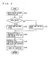
- FIG. 4 a control structure of a program that is executed by engine ECU 300 implementing the control apparatus according to an embodiment of the present invention will be described.
- step (hereinafter, abbreviated as "S") 100 engine ECU 300 detects an engine coolant temperature THW based on data input from coolant temperature sensor 380.
- step 110 engine ECU 300 determines whether the detected engine coolant temperature THW is equal to or higher than a predetermined temperature threshold value THW(TH), which may be set to 70°C to 90°C, for example. If engine coolant temperature THW is equal to or higher than temperature threshold value THW(TH) (YES in S 110), the process goes to S 120. If not (NO in S110), the process goes to S130.
- a predetermined temperature threshold value THW(TH) which may be set to 70°C to 90°C, for example.
- engine ECU 300 selects the map for the warm state ( Fig. 2 ).
- engine ECU 300 selects the map for the cold state ( Fig. 3 ).
- engine ECU 300 calculates DI ratio r from the engine speed and the load factor of engine 10, based on the selected map.
- the engine speed of engine 10 is calculated based on the data input from engine speed sensor 460, and the load factor is calculated based on the data input from accelerator press-down degree sensor 440 as well as the running state of the vehicle.
- engine ECU 300 controls in-cylinder injector 110 and intake manifold injector 120 based on the fuel injection quantity(ies) and the injection timing(s) calculated, to effect the fuel injection.
- engine ECU 300 controls engine 10 assuming that it is in the abnormal operation state that does not correspond to any of Figs. 2-4 .
- the catalyst is inactive, and emission of the exhaust gas into the atmosphere should be suppressed.
- the engine enters a stratified charge combustion mode, and the fuel is injected from in-cylinder injector 110 to realize stratified charge combustion.
- the stratified charge combustion in this case lasts for from some seconds to some tens of seconds.
- stratified charge combustion herein includes both the stratified charge combustion and the semi-stratified charge combustion, as described above.
- the temperature of engine 10 increases after start-up thereof.
- the map for the cold state ( Fig. 3 ) is selected until the temperature of engine 10 (engine coolant temperature THW) reaches a predetermined temperature threshold value (of 80°C, for example) (NO in S110).
- the fuel injection ratio of in-cylinder injector 100 i.e., DI ratio r
- DI ratio r is calculated based on the selected map for the cold state ( Fig. 3 ) and the engine speed and the load factor of engine 10.
- the DI ratio r obtained is used to calculate the fuel injection quantity(ies) and the injection timing(s) (S150), and based thereon, in-cylinder injector 110 and intake manifold injector 120 are controlled to carry out the fuel injection. In this state, homogeneous combustion is effected in any region shown in Fig. 3 .
- the fuel injection ratio of in-cylinder injector 110 i.e., DI ratio r
- DI ratio r is calculated based on the selected map for the warm state ( Fig. 2 ) and the engine speed and the load factor of engine 10. Based on the calculated DI ratio r, the fuel injection quantity(ies) and the injection timing(s) are calculated (S150), and based thereon, in-cylinder injector 110 and intake manifold injector 120 are controlled to carry out the fuel injection. In this state, homogeneous combustion is effected in any region shown in Fig. 2 .
- the fuel injection ratio therebetween is controlled based on the maps that are separately prepared, e.g., for the warm state and the cold state of the internal combustion engine and are set according to the engine speed and the load factor of the engine.
- the control of the fuel injection ratio is carried out based on the maps such that homogeneous combustion is realized over the entire region. Accordingly, the conventional problem associated with control of switching between the stratified charge combustion and the homogeneous combustion, as well as the conventional problem associated with control of the homogeneous combustion in the case of a direct injection engine, can be solved.
- the fuel injection timing of in-cylinder injector 110 is set in the intake stroke in a basic region corresponding to the almost entire region (herein, the basic region refers to the region other than the region where semi-stratified charge combustion is conducted by causing intake manifold injector 120 to inject the fuel in the intake stroke and causing in-cylinder injector 110 to inject the fuel in the compression stroke, which is conducted only in the catalyst warm-up state).
- the fuel injection timing of in-cylinder injector 110 may be set temporarily in the compression stroke for the purpose of stabilizing combustion, for the following reasons.
- the air-fuel mixture is cooled by the injected fuel while the temperature in the cylinder is relatively high. This improves the cooling effect and, hence, the antiknock performance. Further, when the fuel injection timing of in-cylinder injector 110 is set in the compression stroke, the time from the fuel injection to the ignition is short, which ensures strong penetration of the injected fuel, so that the combustion rate increases. The improvement in antiknock performance and the increase in combustion rate can prevent variation in combustion, and thus, combustion stability is improved.
Landscapes
- Engineering & Computer Science (AREA)
- Chemical & Material Sciences (AREA)
- Combustion & Propulsion (AREA)
- Mechanical Engineering (AREA)
- General Engineering & Computer Science (AREA)
- Electrical Control Of Air Or Fuel Supplied To Internal-Combustion Engine (AREA)
- Combined Controls Of Internal Combustion Engines (AREA)
- Fuel-Injection Apparatus (AREA)
Priority Applications (1)
| Application Number | Priority Date | Filing Date | Title |
|---|---|---|---|
| EP10016221A EP2302188B1 (en) | 2004-07-22 | 2005-07-21 | Control apparatus for internal combustion engine |
Applications Claiming Priority (3)
| Application Number | Priority Date | Filing Date | Title |
|---|---|---|---|
| JP2004214627 | 2004-07-22 | ||
| JP2004328063A JP4466337B2 (ja) | 2004-07-22 | 2004-11-11 | 内燃機関の制御装置 |
| PCT/JP2005/013797 WO2006009313A1 (en) | 2004-07-22 | 2005-07-21 | Control apparatus for internal combustion engine |
Related Child Applications (1)
| Application Number | Title | Priority Date | Filing Date |
|---|---|---|---|
| EP10016221.3 Division-Into | 2010-12-31 |
Publications (2)
| Publication Number | Publication Date |
|---|---|
| EP1769152A1 EP1769152A1 (en) | 2007-04-04 |
| EP1769152B1 true EP1769152B1 (en) | 2011-05-11 |
Family
ID=34993279
Family Applications (2)
| Application Number | Title | Priority Date | Filing Date |
|---|---|---|---|
| EP05767330A Ceased EP1769152B1 (en) | 2004-07-22 | 2005-07-21 | Control apparatus for internal combustion engine |
| EP10016221A Ceased EP2302188B1 (en) | 2004-07-22 | 2005-07-21 | Control apparatus for internal combustion engine |
Family Applications After (1)
| Application Number | Title | Priority Date | Filing Date |
|---|---|---|---|
| EP10016221A Ceased EP2302188B1 (en) | 2004-07-22 | 2005-07-21 | Control apparatus for internal combustion engine |
Country Status (6)
| Country | Link |
|---|---|
| US (1) | US7159567B2 (enExample) |
| EP (2) | EP1769152B1 (enExample) |
| JP (1) | JP4466337B2 (enExample) |
| KR (2) | KR20070029277A (enExample) |
| CN (1) | CN1989330B (enExample) |
| WO (1) | WO2006009313A1 (enExample) |
Families Citing this family (24)
| Publication number | Priority date | Publication date | Assignee | Title |
|---|---|---|---|---|
| JP4649142B2 (ja) * | 2004-07-30 | 2011-03-09 | トヨタ自動車株式会社 | 内燃機関の点火時期制御装置 |
| JP4148233B2 (ja) * | 2005-03-29 | 2008-09-10 | トヨタ自動車株式会社 | エンジンの燃料噴射制御装置 |
| JP4453625B2 (ja) | 2005-07-25 | 2010-04-21 | トヨタ自動車株式会社 | 内燃機関の制御装置 |
| US7159568B1 (en) * | 2005-11-30 | 2007-01-09 | Ford Global Technologies, Llc | System and method for engine starting |
| JP4238890B2 (ja) | 2006-07-24 | 2009-03-18 | トヨタ自動車株式会社 | 内燃機関の燃料噴射制御装置 |
| JP2008064032A (ja) * | 2006-09-07 | 2008-03-21 | Toyota Motor Corp | 内燃機関の制御装置、制御方法、その方法を実現するプログラムおよびそのプログラムを記録した記録媒体 |
| US9981104B1 (en) | 2008-02-19 | 2018-05-29 | Circadiance, Llc | Full face cloth respiratory mask |
| DE102008002511B4 (de) | 2008-06-18 | 2018-12-20 | Robert Bosch Gmbh | Verfahren und Vorrichtung zum Betreiben einer Brennkraftmaschine bei kombinierter Direkt- und Saugrohreinspritzung, Computerprogramm, Computerprogrammprodukt |
| CN101832189B (zh) * | 2010-04-23 | 2013-06-12 | 北京锐意泰克汽车电子有限公司 | 一种汽车发动机进气歧管状态的控制方法 |
| JP5776601B2 (ja) * | 2012-03-28 | 2015-09-09 | トヨタ自動車株式会社 | 燃料噴射制御装置 |
| GB2505512A (en) * | 2012-09-03 | 2014-03-05 | Gm Global Tech Operations Inc | Method of controlling a rich combustion mode of an internal combustion engine |
| JP5737262B2 (ja) * | 2012-10-16 | 2015-06-17 | トヨタ自動車株式会社 | 内燃機関の制御装置 |
| WO2016075784A1 (ja) * | 2014-11-13 | 2016-05-19 | 日産自動車株式会社 | 内燃機関の燃料噴射制御装置および燃料噴射制御方法 |
| WO2016084187A1 (ja) * | 2014-11-27 | 2016-06-02 | 日産自動車株式会社 | 内燃機関の燃料噴射制御装置および燃料噴射制御方法 |
| DE102015214930B4 (de) * | 2015-08-05 | 2017-02-23 | Robert Bosch Gmbh | Verfahren zum Ändern einer Aufteilung auf Saugrohreinspritzung und Direkteinspritzung bei einer Brennkraftmaschine |
| JP2017057797A (ja) * | 2015-09-17 | 2017-03-23 | 日立オートモティブシステムズ株式会社 | 燃料噴射制御装置 |
| DE102015219042A1 (de) * | 2015-10-01 | 2017-04-06 | Robert Bosch Gmbh | Verfahren zum Betreiben eines Verbrennungsmotors |
| DE102015221914A1 (de) * | 2015-11-09 | 2017-05-11 | Robert Bosch Gmbh | Verfahren und Vorrichtung zum Betrieb einer Brennkraftmaschine insbesondere eines Kraftfahrzeugs mit dualer Kraftstoffeinspritzung |
| DE102015223316A1 (de) * | 2015-11-25 | 2017-06-01 | Robert Bosch Gmbh | Verfahren zum Betreiben eines Verbrennungsmotors |
| US9920705B2 (en) * | 2015-12-16 | 2018-03-20 | Robert Bosch, Llc | Fuel injection system and method |
| JP6638668B2 (ja) * | 2017-02-14 | 2020-01-29 | トヨタ自動車株式会社 | 燃料噴射制御装置 |
| JP7798017B2 (ja) * | 2022-12-20 | 2026-01-14 | トヨタ自動車株式会社 | 燃料噴射制御装置 |
| JP7816243B2 (ja) * | 2023-03-24 | 2026-02-18 | トヨタ自動車株式会社 | エンジン装置 |
| CN119222056B (zh) * | 2024-09-24 | 2026-03-24 | 长城汽车股份有限公司 | 一种发动机的冷起动方法和车辆 |
Family Cites Families (15)
| Publication number | Priority date | Publication date | Assignee | Title |
|---|---|---|---|---|
| JPH0658067B2 (ja) * | 1983-08-09 | 1994-08-03 | マツダ株式会社 | 層状給気エンジン |
| US5549087A (en) * | 1995-04-27 | 1996-08-27 | The United States Of America As Represented By The Administrator Of The U.S. Environmental Protection Agency | Combined cycle engine |
| JP3362616B2 (ja) | 1996-12-09 | 2003-01-07 | トヨタ自動車株式会社 | 成層燃焼内燃機関の燃料噴射制御装置 |
| JPH10176574A (ja) * | 1996-12-19 | 1998-06-30 | Toyota Motor Corp | 内燃機関の燃料噴射制御装置 |
| JP3414303B2 (ja) * | 1998-03-17 | 2003-06-09 | 日産自動車株式会社 | 直噴火花点火式内燃機関の制御装置 |
| JPH11351041A (ja) | 1998-06-08 | 1999-12-21 | Fuji Heavy Ind Ltd | 燃料噴射式内燃機関 |
| JP2001020837A (ja) | 1999-07-07 | 2001-01-23 | Nissan Motor Co Ltd | エンジンの燃料噴射制御装置 |
| JP2001164283A (ja) * | 1999-12-10 | 2001-06-19 | Tonengeneral Sekiyu Kk | 内燃機関用潤滑油組成物 |
| AU2001261245A1 (en) * | 2000-05-08 | 2001-11-20 | Cummins, Inc. | Multiple operating mode engine and method of operation |
| JP3791322B2 (ja) | 2000-10-26 | 2006-06-28 | 日産自動車株式会社 | 筒内直接噴射式火花点火エンジンの制御装置 |
| JP2002276423A (ja) * | 2001-03-22 | 2002-09-25 | Komatsu Ltd | エンジンの燃料噴射制御装置 |
| JP4423816B2 (ja) | 2001-06-06 | 2010-03-03 | トヨタ自動車株式会社 | 筒内噴射式内燃機関の燃料噴射制御装置 |
| AT5646U1 (de) * | 2001-08-27 | 2002-09-25 | Avl List Gmbh | Verfahren zum betrieb einer brennkraftmaschine |
| JP3941441B2 (ja) | 2001-09-11 | 2007-07-04 | トヨタ自動車株式会社 | 内燃機関の始動時制御装置 |
| JP4063197B2 (ja) * | 2003-11-11 | 2008-03-19 | トヨタ自動車株式会社 | 内燃機関の噴射制御装置 |
-
2004
- 2004-11-11 JP JP2004328063A patent/JP4466337B2/ja not_active Expired - Lifetime
-
2005
- 2005-07-20 US US11/184,993 patent/US7159567B2/en not_active Expired - Lifetime
- 2005-07-21 WO PCT/JP2005/013797 patent/WO2006009313A1/en not_active Ceased
- 2005-07-21 KR KR1020077002172A patent/KR20070029277A/ko not_active Ceased
- 2005-07-21 EP EP05767330A patent/EP1769152B1/en not_active Ceased
- 2005-07-21 EP EP10016221A patent/EP2302188B1/en not_active Ceased
- 2005-07-21 KR KR1020087014756A patent/KR100912844B1/ko not_active Expired - Fee Related
- 2005-07-21 CN CN2005800247696A patent/CN1989330B/zh not_active Expired - Fee Related
Also Published As
| Publication number | Publication date |
|---|---|
| EP2302188B1 (en) | 2012-03-28 |
| US7159567B2 (en) | 2007-01-09 |
| KR20080070751A (ko) | 2008-07-30 |
| EP1769152A1 (en) | 2007-04-04 |
| JP4466337B2 (ja) | 2010-05-26 |
| EP2302188A1 (en) | 2011-03-30 |
| WO2006009313A1 (en) | 2006-01-26 |
| CN1989330B (zh) | 2010-05-26 |
| CN1989330A (zh) | 2007-06-27 |
| US20060016430A1 (en) | 2006-01-26 |
| KR100912844B1 (ko) | 2009-08-18 |
| KR20070029277A (ko) | 2007-03-13 |
| JP2006057624A (ja) | 2006-03-02 |
Similar Documents
| Publication | Publication Date | Title |
|---|---|---|
| CA2576439C (en) | Control apparatus for internal combustion engine | |
| EP1769152B1 (en) | Control apparatus for internal combustion engine | |
| US7198031B2 (en) | Control device of internal combustion engine | |
| EP1859140B1 (en) | Control apparatus for internal combustion engine | |
| US7610899B2 (en) | Control apparatus for internal combustion engine | |
| US7367317B2 (en) | Control apparatus for internal combustion engine | |
| EP1812702B1 (en) | Control apparatus for internal combustion engine | |
| EP1859146B1 (en) | Control device for internal combustion engine |
Legal Events
| Date | Code | Title | Description |
|---|---|---|---|
| PUAI | Public reference made under article 153(3) epc to a published international application that has entered the european phase |
Free format text: ORIGINAL CODE: 0009012 |
|
| 17P | Request for examination filed |
Effective date: 20061218 |
|
| AK | Designated contracting states |
Kind code of ref document: A1 Designated state(s): DE FR GB IT |
|
| DAX | Request for extension of the european patent (deleted) | ||
| RBV | Designated contracting states (corrected) |
Designated state(s): DE FR GB IT |
|
| 17Q | First examination report despatched |
Effective date: 20081223 |
|
| GRAP | Despatch of communication of intention to grant a patent |
Free format text: ORIGINAL CODE: EPIDOSNIGR1 |
|
| GRAS | Grant fee paid |
Free format text: ORIGINAL CODE: EPIDOSNIGR3 |
|
| GRAA | (expected) grant |
Free format text: ORIGINAL CODE: 0009210 |
|
| RIN1 | Information on inventor provided before grant (corrected) |
Inventor name: SUGIYAMA, MASANORI, C/O TOYOTA JIDOSHA K.K. Inventor name: HARADA, JUN, C/O TOYOTA JIDOSHA K. K. Inventor name: ABE, SHIZUO, C/O TOYOTA JIDOSHA K. K. Inventor name: IKOMA, TAKUYA, C/O TOYOTA JIDOSHA K. K. Inventor name: SATOU, FUMIKAZU, C/O TOYOTA JIDOSHA K. K. Inventor name: SADAKANE, SHINJI, C/O TOYOTA JIDOSHA K.K. Inventor name: IWAHASHI, KAZUHIRO, C/O TOYOTA JIDOSHA K.K. Inventor name: TSUCHIYA, TOMIHISA, C/O TOYOTA JIDOSHA K.K. |
|
| AK | Designated contracting states |
Kind code of ref document: B1 Designated state(s): DE FR GB IT |
|
| REG | Reference to a national code |
Ref country code: GB Ref legal event code: FG4D |
|
| REG | Reference to a national code |
Ref country code: DE Ref legal event code: R096 Ref document number: 602005027996 Country of ref document: DE Effective date: 20110622 |
|
| PLBE | No opposition filed within time limit |
Free format text: ORIGINAL CODE: 0009261 |
|
| STAA | Information on the status of an ep patent application or granted ep patent |
Free format text: STATUS: NO OPPOSITION FILED WITHIN TIME LIMIT |
|
| 26N | No opposition filed |
Effective date: 20120214 |
|
| REG | Reference to a national code |
Ref country code: DE Ref legal event code: R097 Ref document number: 602005027996 Country of ref document: DE Effective date: 20120214 |
|
| REG | Reference to a national code |
Ref country code: GB Ref legal event code: 746 Effective date: 20130412 |
|
| REG | Reference to a national code |
Ref country code: DE Ref legal event code: R084 Ref document number: 602005027996 Country of ref document: DE Effective date: 20130410 |
|
| REG | Reference to a national code |
Ref country code: FR Ref legal event code: PLFP Year of fee payment: 12 |
|
| REG | Reference to a national code |
Ref country code: FR Ref legal event code: PLFP Year of fee payment: 13 |
|
| REG | Reference to a national code |
Ref country code: FR Ref legal event code: PLFP Year of fee payment: 14 |
|
| PGFP | Annual fee paid to national office [announced via postgrant information from national office to epo] |
Ref country code: GB Payment date: 20180718 Year of fee payment: 14 |
|
| PGFP | Annual fee paid to national office [announced via postgrant information from national office to epo] |
Ref country code: FR Payment date: 20190619 Year of fee payment: 15 |
|
| PGFP | Annual fee paid to national office [announced via postgrant information from national office to epo] |
Ref country code: IT Payment date: 20190719 Year of fee payment: 15 Ref country code: DE Payment date: 20190710 Year of fee payment: 15 |
|
| GBPC | Gb: european patent ceased through non-payment of renewal fee |
Effective date: 20190721 |
|
| PG25 | Lapsed in a contracting state [announced via postgrant information from national office to epo] |
Ref country code: GB Free format text: LAPSE BECAUSE OF NON-PAYMENT OF DUE FEES Effective date: 20190721 |
|
| REG | Reference to a national code |
Ref country code: DE Ref legal event code: R119 Ref document number: 602005027996 Country of ref document: DE |
|
| PG25 | Lapsed in a contracting state [announced via postgrant information from national office to epo] |
Ref country code: FR Free format text: LAPSE BECAUSE OF NON-PAYMENT OF DUE FEES Effective date: 20200731 |
|
| PG25 | Lapsed in a contracting state [announced via postgrant information from national office to epo] |
Ref country code: DE Free format text: LAPSE BECAUSE OF NON-PAYMENT OF DUE FEES Effective date: 20210202 |
|
| PG25 | Lapsed in a contracting state [announced via postgrant information from national office to epo] |
Ref country code: IT Free format text: LAPSE BECAUSE OF NON-PAYMENT OF DUE FEES Effective date: 20200721 |