EP1768228B1 - Machine électrique avec fixation ameliorée d'un élément de reflux - Google Patents
Machine électrique avec fixation ameliorée d'un élément de reflux Download PDFInfo
- Publication number
- EP1768228B1 EP1768228B1 EP20060118633 EP06118633A EP1768228B1 EP 1768228 B1 EP1768228 B1 EP 1768228B1 EP 20060118633 EP20060118633 EP 20060118633 EP 06118633 A EP06118633 A EP 06118633A EP 1768228 B1 EP1768228 B1 EP 1768228B1
- Authority
- EP
- European Patent Office
- Prior art keywords
- return element
- pole housing
- electrical machine
- tooth
- magnetic return
- Prior art date
- Legal status (The legal status is an assumption and is not a legal conclusion. Google has not performed a legal analysis and makes no representation as to the accuracy of the status listed.)
- Expired - Fee Related
Links
Images

Classifications
-
- H—ELECTRICITY
- H02—GENERATION; CONVERSION OR DISTRIBUTION OF ELECTRIC POWER
- H02K—DYNAMO-ELECTRIC MACHINES
- H02K1/00—Details of the magnetic circuit
- H02K1/06—Details of the magnetic circuit characterised by the shape, form or construction
- H02K1/12—Stationary parts of the magnetic circuit
- H02K1/18—Means for mounting or fastening magnetic stationary parts on to, or to, the stator structures
- H02K1/185—Means for mounting or fastening magnetic stationary parts on to, or to, the stator structures to outer stators
-
- H—ELECTRICITY
- H02—GENERATION; CONVERSION OR DISTRIBUTION OF ELECTRIC POWER
- H02K—DYNAMO-ELECTRIC MACHINES
- H02K1/00—Details of the magnetic circuit
- H02K1/06—Details of the magnetic circuit characterised by the shape, form or construction
- H02K1/12—Stationary parts of the magnetic circuit
- H02K1/17—Stator cores with permanent magnets
Definitions
- the present invention relates to an electric machine, in particular an electric motor, which has an improved attachment of a return element to a pole housing.
- Electric machines are known from the prior art in a variety of configurations.
- return rings are used to better conduct a magnetic flux. It is known that these return rings either enclose a pole housing of the electric motor or they are arranged in the interior of the pole housing.
- the return rings usually have a ring-cylindrical shape.
- one or more magnets are first fixed in the interior of the ring for mounting and then the yoke ring is inserted into the pole housing.
- a press fit is usually chosen between the return ring and the pole housing.
- the DE 3904516 C1 shows a permanent-magnet electric machine with a pole housing in which permanent magnetic pole rings are arranged, which are coupled together by means of a yoke ring. The magnetic pole rings are pressed in the radial direction against the yoke ring.
- the DE 102004018524 A1 discloses an outer stator return element which is at least partially made of a powder composite material. The return element is clamped axially into a holder of the pole housing.
- connection between a pole housing and a return element of the electrical machine comprises a first connection region and a second connection region, wherein the first connection region is formed with a press fit and the second connection region with a clearance fit.
- the entire connection between the pole housing and the return element is no longer provided by a press fit, but an interference fit is only partially provided, the press fit region being selected such that only a minimal influence of the joining forces on the other components, in particular the magnets, is available. According to the invention, however, an accurate positioning and a good fixation of the two components can still be made possible.
- connection comprises a toothing, wherein the toothing comprises at least one tooth with a left and a right tooth flank, a tooth tip and a tooth root.
- the press-fitting having first connection region is formed on the left and right tooth flank.
- the second connection region which has the clearance, is formed at least on the tooth tip and / or on the tooth root.
- a defined air gap is present in the assembled state on the tooth head and / or on the tooth root of the toothing.
- dimensional specifications for the tolerances of the tooth root and / or the tooth head are provided in such a way that the defined air gap is present even with maximum tolerance deviation.
- the toothing is formed along the entire circumference between the return element and the pole housing.
- the toothing is formed only partially along the circumference between the return element and the hollow housing.
- the toothing is arranged symmetrically distributed on the circumference.
- an angle of the left and right tooth flanks is preferably selected in a range between 50 ° and 90 °.
- the tooth flanks are formed relatively steep, so that the forces resulting from the joining and voltages are minimized, especially in the radial direction.
- radial stresses on the magnet can be minimized.
- the return element is disposed within the pole housing. According to an alternative preferred embodiment of the invention, the return element is arranged outside of the pole housing.
- the return element is preferably formed with a slot.
- the slot is preferably formed in the axial direction of the return element parallel to a central axis of the return element. More preferably, the slot is formed such that it does not pass completely through the return element in the longitudinal direction, but that it only has a certain depth.
- the return element and the magnet is provided as a pre-assembly. As a result, only the subassembly still has to be joined to the pole housing.
- the electric machine is preferably an electric motor which is used in vehicles, in particular in comfort applications in the vehicle, e.g. Seat adjustment, windows, sunroof etc. is used.
- FIGS. 1 to 5 an electric machine according to a first embodiment of the invention described.
- the electric machine is not fully shown, but only relevant to the invention main components of the electric machine.
- the electric machine can, for example, a Electric motor, which is used as a comfort drive in vehicles.
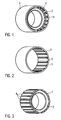
- the electric machine comprises a pole housing 1, which is formed substantially as a cylindrical ring.
- the pole housing 1 is shown in detail in FIG FIG. 2 shown. How out FIG. 2 it can be seen, a plurality of teeth 5 is formed on the inner circumference of the pole housing 1.
- the teeth 5 extend in the axial direction of the pole housing 1 and are arranged uniformly along the inner circumference of the pole housing.
- the teeth should run along the entire length of the pole housing 1.
- the return ring should be at least as long as the magnet, the toothing is ideally along the total length of the return ring, ie, the teeth in the pole housing does not necessarily have to be formed over its overall length, but ideally adapts to the length of the return ring or its tooth length.
- the teeth 5 arranged on the inner circumference of the pole housing 1 are part of a connection 4 between the pole housing 1 and a return element 2 designed as a return ring.
- the return element 2 is made in detail FIG. 3 seen. As in FIG. 3 shown, a toothing with a plurality of teeth 6 is formed on the outer circumference of the return element 2.
- the outwardly directed teeth 6 of the return element 2 are formed in a uniform manner along the outer circumference.
- the teeth 6 also run over the entire axial length of the return element 2. It should be noted that the axial length of the return element 2 is equal to the axial length of the pole housing 1.
- the teeth 5 of the pole housing 1 and the teeth 6 of the return element 2 are formed symmetrically to a plane through a tooth center.
- a ring magnet 3 is shown schematically. It should be noted that here a plurality of individual magnets may be provided.
- the ring magnet 3 is connected to the return element 2, for example, by gluing.
- FIG. 4 shows the assembled state of the return element 2 together with the magnet 3 in the pole housing 1.
- the connection 4 between the pole housing 1 and the return element 2 is on an enlarged scale in FIG. 5 shown. How out FIG. 5 it can be seen, the connection 4 between the pole housing 1 and the return element 2 is formed by a first connection region 7 and a second connection region 8.
- the first connection region 7 forms a press fit between the pole housing 1 and the return element 2.
- the second connection region 8 forms a clearance fit between the return element 2 and the pole housing 1.
- the teeth 5 of the pole housing 1 in this case have a tooth tip 5a, a first tooth flank 5b, a second tooth flank 5c and a tooth space 5d.
- the teeth 6 of the return element 2 have a tooth tip 6a, a first tooth flank 6b, a second tooth flank 6c and a tooth space 6d.
- FIG. 5 it can be seen, in this case the interference fit between the hollow housing 1 and the return element 2 is formed in each case on the tooth flanks 5b, 6b and 5c, 6c.
- this interference fit between the tooth flanks of the teeth 5 and 6 forms the first connection region of the connection 4 between the pole housing 1 and the return element 2
- FIG. 6 it can be seen, a gap 10 is formed in the region between the tooth tips 5a of the teeth 5 and the tooth spaces 6d of the teeth 6. As in FIG. 5 As shown, the gap 10 has a width f.
- a gap 11 is further formed, which, as in FIG. 5 shown having a width k.
- the opposite tooth heads and interdental spaces of the teeth 5 and 6 form the second Connecting region with clearance fit between the pole housing and the return element 2.
- the tooth flanks 5b, 5c and 6b, 6c have an angle ⁇ , which is approximately 70 °. This angle is relatively steep, so that the magnet 3 remains substantially unaffected by the joining forces occurring during joining at the first connection region 7.
- ⁇ which is approximately 70 °. This angle is relatively steep, so that the magnet 3 remains substantially unaffected by the joining forces occurring during joining at the first connection region 7.
- the assembly can be done easily and manufacturing tolerances of the pole housing and the return element, in particular in the range of the diameter of these components, have no negative impact on the assembly. Since the magnet 3 was attached to the yoke element 2 before the joining of the yoke element 2 in the pole housing 1, this is mounted together with the yoke element in the pole housing 1.
- a press fit on two tooth flanks of the teeth 5, 6 is sufficient. It should also be noted that a circumferential length of the teeth 6 of the return element 2 is approximately twice as long as a circumferential length of the teeth 5 of the pole housing 1 (see. FIG. 5 ).
- FIG. 6 shows a return element 2 according to a second embodiment of the invention.
- the inference element 2 of the second embodiment substantially corresponds to the first embodiment, wherein in contrast to the first embodiment additionally a plurality of slots 12 are formed.
- the slots 12 are not formed over the entire length of the return element 2.
- the slots 12 ensure that in particular forces and stresses in the circumferential direction can be partially absorbed by the return element 2 and thus can not lead to damage of the magnet 3 during assembly. Otherwise, this embodiment corresponds to the first embodiment, so that reference may be made to the description given there.
- FIG. 7 shows a return element 2 according to a third embodiment of the invention.
- the third embodiment substantially corresponds to the first embodiment, wherein, unlike the first embodiment in the third embodiment, the teeth formed by the teeth 6 is not formed completely along the entire circumference of the return element 2.
- four areas 13 are provided, each with three teeth 6.
- the regions 13 are distributed uniformly along the outer circumference of the return element 2. Between the regions 13, planar circumferential surfaces 14 are formed on the outer circumference of the return element 2. Otherwise, this embodiment corresponds to the first embodiment, so that reference may be made to the description given there.
- the invention is not limited to the described embodiments. Rather, the described embodiments, in which modifications of the return element 2 have been described, are also modified in such a way that the modification described by way of example on the return element 2 can also be made on the pole housing. It should also be noted that it is also possible that the pole housing is disposed within the return element and the corresponding connection between the outer yoke element and the inner pole housing as in the illustrated embodiments is executed.
Landscapes
- Engineering & Computer Science (AREA)
- Power Engineering (AREA)
- Permanent Field Magnets Of Synchronous Machinery (AREA)
- Iron Core Of Rotating Electric Machines (AREA)
- Dc Machiner (AREA)
Claims (12)
- Machine électrique comprenant un boîtier polaire (1), un aimant (3) et un élément de fermeture (2),
une liaison (4) avec une première zone de liaison (7) et une deuxième zone de liaison (8) étant formées entre le boîtier polaire (1) et l'élément de fermeture (2), la deuxième zone de liaison présentant un jeu,
caractérisée en ce que
la première partie de liaison (7) comprend une adaptation par poussée. - Machine électrique selon la revendication 1, caractérisée en ce que la liaison (4) comprend une dentelure, en ce qu'au moins une dent (5, 6) de la dentelure présente un premier flanc (5b, 6b) de dent et un deuxième blanc (5c, 6c) de dent, une tête (5a, 6a) de dent et un espace (5d, 6d) inter-dentaire et en ce que la première partie de liaison (7) qui présente l'adaptation par poussée est formée sur le premier et le deuxième flanc (5b, 5c, 6b, 6c) des dents.
- Machine électrique selon la revendication 2, caractérisée en ce que lorsqu'elle est montée entre le boîtier polaire (1) et l'élément de fermeture (2), un interstice (10, 11) est formé sur la tête (5a, 6a) de dent et/ou dans l'espace (5d, 6d) inter-dentaire.
- Machine électrique selon les revendications 2 ou 3, caractérisée en ce que la dentelure est formée sur toute la périphérie entre le boîtier polaire (1) et l'élément de fermeture (2).
- Machine électrique selon les revendications 2 ou 3, caractérisée en ce que la dentelure n'est formée que sur une partie de la périphérie, en des zones (13) situées entre le boîtier polaire (1) et l'élément de fermeture (2).
- Machine électrique selon l'une des revendications 2 à 5, caractérisée en ce que l'angle (α) entre le premier et le deuxième flanc des dents est compris entre 50° et 90°.
- Machine électrique selon l'une des revendications précédentes, caractérisée en ce que l'élément de fermeture (2) est disposé à l'intérieur du boîtier polaire (1).
- Machine électrique selon l'une des revendications 1 à 6, caractérisée en ce que l'élément de fermeture (2) est disposé à l'extérieur du boîtier polaire (1).
- Machine électrique selon l'une des revendications précédentes, caractérisée en ce que l'élément de fermeture (2) et/ou le boîtier polaire (1) comprennent une fente (12) et en ce que la fente (12) n'est formée que sur une certaine longueur axiale.
- Machine électrique selon la revendication 9, caractérisée en ce que la fente (12) est formée dans la direction axiale parallèlement à l'axe central de l'élément de fermeture (2).
- Machine électrique selon l'une des revendications précédentes, caractérisée en ce que l'élément de fermeture (2) et l'aimant (3) forment un module préfabriqué.
- Dispositif de confort pour un véhicule, comprenant une machine électrique et en particulier un moteur électrique selon l'une des revendications précédentes.
Applications Claiming Priority (1)
| Application Number | Priority Date | Filing Date | Title |
|---|---|---|---|
| DE200510045396 DE102005045396A1 (de) | 2005-09-23 | 2005-09-23 | Elektrische Maschine mit verbesserter Befestigung eines Rückschlusselements |
Publications (3)
| Publication Number | Publication Date |
|---|---|
| EP1768228A1 EP1768228A1 (fr) | 2007-03-28 |
| EP1768228B1 true EP1768228B1 (fr) | 2010-06-09 |
| EP1768228B2 EP1768228B2 (fr) | 2013-09-25 |
Family
ID=37531817
Family Applications (1)
| Application Number | Title | Priority Date | Filing Date |
|---|---|---|---|
| EP06118633.4A Expired - Fee Related EP1768228B2 (fr) | 2005-09-23 | 2006-08-09 | Machine électrique avec fixation ameliorée d'un élément de reflux |
Country Status (2)
| Country | Link |
|---|---|
| EP (1) | EP1768228B2 (fr) |
| DE (2) | DE102005045396A1 (fr) |
Families Citing this family (1)
| Publication number | Priority date | Publication date | Assignee | Title |
|---|---|---|---|---|
| DE102022210700A1 (de) | 2022-10-11 | 2024-04-11 | Robert Bosch Gesellschaft mit beschränkter Haftung | Elektronisch kommutierter Elektromotor in Außenläuferbauart und Verfahren zu dessen Herstellung |
Family Cites Families (7)
| Publication number | Priority date | Publication date | Assignee | Title |
|---|---|---|---|---|
| US4250423A (en) | 1978-08-25 | 1981-02-10 | Sundstrand Corporation | Generator with stator retention |
| DE3904516C1 (fr) | 1989-02-15 | 1990-06-13 | Robert Bosch Gmbh, 7000 Stuttgart, De | |
| DE19652263A1 (de) † | 1996-12-16 | 1998-06-18 | Bosch Gmbh Robert | Rotor für Elektrokleinmotoren |
| DE10358456A1 (de) † | 2003-12-13 | 2005-07-07 | Zf Friedrichshafen Ag | Rotor für eine elektrische Maschine |
| DE102004018524A1 (de) | 2004-04-14 | 2005-11-03 | Voith Turbo Gmbh & Co. Kg | Außenstator-Rückschlusselement und Statoreinheit |
| DE102004018523B4 (de) * | 2004-04-14 | 2007-10-04 | Voith Turbo Gmbh & Co. Kg | Statoreinheit mit Außenstator-Rückschlußelementen |
| FR2876231B1 (fr) * | 2004-05-06 | 2006-12-22 | Gerard Koehler | Machine dynamo-electrique tournante a reluctance variable a globalisation des circuits magnetiques, electriques et de polarisation et son procede de fabrication |
-
2005
- 2005-09-23 DE DE200510045396 patent/DE102005045396A1/de not_active Withdrawn
-
2006
- 2006-08-09 EP EP06118633.4A patent/EP1768228B2/fr not_active Expired - Fee Related
- 2006-08-09 DE DE200650007152 patent/DE502006007152D1/de active Active
Also Published As
| Publication number | Publication date |
|---|---|
| DE102005045396A1 (de) | 2007-03-29 |
| EP1768228B2 (fr) | 2013-09-25 |
| DE502006007152D1 (de) | 2010-07-22 |
| EP1768228A1 (fr) | 2007-03-28 |
Similar Documents
| Publication | Publication Date | Title |
|---|---|---|
| DE102011054956B4 (de) | Antriebseinheit für einen Stellantrieb mit einem Elektromotor und zugehöriger Stellantrieb | |
| DE102015224775A1 (de) | Spindelantrieb und Aktuator mit Spindelantrieb | |
| DE102008025781A1 (de) | Verstellbare Nockenwellenanordnung | |
| DE102012014208A1 (de) | Vorrichtung mit einer Drehmomentsensoreinrichtung und optional einer Lenkwinkelsenoreinrichtung für ein Kraftfahrzeug und Verfahren zum Zusammenbauen einer solchen Vorrichtung aus mehreren Bauteilen | |
| DE202015102802U1 (de) | Werkzeugspannsystem | |
| DE102009034626A1 (de) | Baugruppe bestehend aus einem Ausgleichsbehälter und einem Hauptzylinder für eine hydraulische Kraftfahrzeugbremsanlage | |
| DE102015222005A1 (de) | Fördereinrichtung | |
| DE112020002960T5 (de) | Steer-by-wire-lenkvorrichtung | |
| DE102013223241B4 (de) | Wärmeträgermediumanschlussbaugruppe, insbesondere für eine Wärmetauscheranordnung eines Fahrzeugheizgeräts | |
| EP2837083A2 (fr) | Stator en plusieurs parties pour un moteur électrique et moteur électrique correspondant | |
| EP2999094B1 (fr) | Arbre en saillie pour un moteur électrique, moteur électrique doté d'un arbre en saillie, utilisation d'un arbre en saillie en tant qu'arbre de commande d'un encodeur et procédé de liaison d'un arbre en saillie à un arbre de commande d'un moteur électrique | |
| EP2336495B1 (fr) | Turbosoufflante de gaz d'échappement | |
| DE102009032088A1 (de) | Elektromotor mit Anbaugehäuse | |
| EP1768228B1 (fr) | Machine électrique avec fixation ameliorée d'un élément de reflux | |
| DE102019218515A1 (de) | Steer-by-Wire Lenksystem für ein Kraftfahrzeug | |
| EP2861948A2 (fr) | Dispositif de détection permettant de mesurer une grandeur caractéristique d'un état de rotation d'un élément arbre d'un véhicule automobile, véhicule automobile et procédé de fabrication d'un dispositif de détection | |
| DE102010031170A1 (de) | Motor-Getriebe-Anordnung, Motorgehäuse und Getriebegehäuseanordnung hierfür, Verfahren zum Montieren sowie Vorrichtung und Verfahren zur Herstellung | |
| DE102018210158A1 (de) | Baueinheit aus einer elektrischen Maschine und einem Tragelement | |
| DE102013226712A1 (de) | Kugelrückführungsvorrichtung für eine Kugelgewindemutter, Klammer zur Fixierung einer Kugelrückführungsvorrichtung, Kugelgewindemutter sowie Anordnung einer Kugelrückführungsvorrichtung an einer Kugelgewindemutter | |
| DE102024000570A1 (de) | Lenkungsanordnung mit Schraubenführung für ein Fahrzeug | |
| EP1902192B1 (fr) | Procede et dispositif de fixation d'une unite entrainement a engrenage a une partie de la carrosserie d'un vehicule a moteur | |
| DE102014015783B4 (de) | Lenkanordnung für ein Kraftfahrzeug und Kraftfahrzeug mit Lenkanordnung | |
| DE102015219855A1 (de) | Hohlrad mit Innenverzahnung und Kronenverzahnung, sowie Verfahren zu dessen Herstellung und Schaltgetriebe mit solchem Hohlrad | |
| DE102021209115A1 (de) | Elektrische Maschine in Innenläuferbauart | |
| DE102021205499A1 (de) | Antriebsvorrichtung und Statorbaugruppe hierfür |
Legal Events
| Date | Code | Title | Description |
|---|---|---|---|
| PUAI | Public reference made under article 153(3) epc to a published international application that has entered the european phase |
Free format text: ORIGINAL CODE: 0009012 |
|
| AK | Designated contracting states |
Kind code of ref document: A1 Designated state(s): AT BE BG CH CY CZ DE DK EE ES FI FR GB GR HU IE IS IT LI LT LU LV MC NL PL PT RO SE SI SK TR |
|
| AX | Request for extension of the european patent |
Extension state: AL BA HR MK YU |
|
| 17P | Request for examination filed |
Effective date: 20070928 |
|
| AKX | Designation fees paid |
Designated state(s): DE ES FR HU IT |
|
| 17Q | First examination report despatched |
Effective date: 20071108 |
|
| GRAP | Despatch of communication of intention to grant a patent |
Free format text: ORIGINAL CODE: EPIDOSNIGR1 |
|
| GRAS | Grant fee paid |
Free format text: ORIGINAL CODE: EPIDOSNIGR3 |
|
| GRAA | (expected) grant |
Free format text: ORIGINAL CODE: 0009210 |
|
| AK | Designated contracting states |
Kind code of ref document: B1 Designated state(s): DE ES FR HU IT |
|
| REF | Corresponds to: |
Ref document number: 502006007152 Country of ref document: DE Date of ref document: 20100722 Kind code of ref document: P |
|
| PLBI | Opposition filed |
Free format text: ORIGINAL CODE: 0009260 |
|
| PG25 | Lapsed in a contracting state [announced via postgrant information from national office to epo] |
Ref country code: IT Free format text: LAPSE BECAUSE OF FAILURE TO SUBMIT A TRANSLATION OF THE DESCRIPTION OR TO PAY THE FEE WITHIN THE PRESCRIBED TIME-LIMIT Effective date: 20100609 |
|
| PLAX | Notice of opposition and request to file observation + time limit sent |
Free format text: ORIGINAL CODE: EPIDOSNOBS2 |
|
| 26 | Opposition filed |
Opponent name: ZF FRIEDRICHSHAFEN AG Effective date: 20110309 |
|
| REG | Reference to a national code |
Ref country code: DE Ref legal event code: R026 Ref document number: 502006007152 Country of ref document: DE Effective date: 20110309 |
|
| PLBB | Reply of patent proprietor to notice(s) of opposition received |
Free format text: ORIGINAL CODE: EPIDOSNOBS3 |
|
| PG25 | Lapsed in a contracting state [announced via postgrant information from national office to epo] |
Ref country code: HU Free format text: LAPSE BECAUSE OF FAILURE TO SUBMIT A TRANSLATION OF THE DESCRIPTION OR TO PAY THE FEE WITHIN THE PRESCRIBED TIME-LIMIT Effective date: 20101210 |
|
| PUAH | Patent maintained in amended form |
Free format text: ORIGINAL CODE: 0009272 |
|
| STAA | Information on the status of an ep patent application or granted ep patent |
Free format text: STATUS: PATENT MAINTAINED AS AMENDED |
|
| 27A | Patent maintained in amended form |
Effective date: 20130925 |
|
| AK | Designated contracting states |
Kind code of ref document: B2 Designated state(s): DE ES FR HU IT |
|
| PG25 | Lapsed in a contracting state [announced via postgrant information from national office to epo] |
Ref country code: ES Free format text: LAPSE BECAUSE OF FAILURE TO SUBMIT A TRANSLATION OF THE DESCRIPTION OR TO PAY THE FEE WITHIN THE PRESCRIBED TIME-LIMIT Effective date: 20100920 |
|
| REG | Reference to a national code |
Ref country code: DE Ref legal event code: R102 Ref document number: 502006007152 Country of ref document: DE Effective date: 20130925 |
|
| REG | Reference to a national code |
Ref country code: DE Ref legal event code: R084 Ref document number: 502006007152 Country of ref document: DE |
|
| REG | Reference to a national code |
Ref country code: DE Ref legal event code: R084 Ref document number: 502006007152 Country of ref document: DE Effective date: 20150506 |
|
| REG | Reference to a national code |
Ref country code: FR Ref legal event code: PLFP Year of fee payment: 11 |
|
| REG | Reference to a national code |
Ref country code: FR Ref legal event code: PLFP Year of fee payment: 12 |
|
| PGFP | Annual fee paid to national office [announced via postgrant information from national office to epo] |
Ref country code: FR Payment date: 20170823 Year of fee payment: 12 |
|
| PGFP | Annual fee paid to national office [announced via postgrant information from national office to epo] |
Ref country code: DE Payment date: 20181024 Year of fee payment: 13 |
|
| PG25 | Lapsed in a contracting state [announced via postgrant information from national office to epo] |
Ref country code: FR Free format text: LAPSE BECAUSE OF NON-PAYMENT OF DUE FEES Effective date: 20180831 |
|
| REG | Reference to a national code |
Ref country code: DE Ref legal event code: R119 Ref document number: 502006007152 Country of ref document: DE |
|
| PG25 | Lapsed in a contracting state [announced via postgrant information from national office to epo] |
Ref country code: DE Free format text: LAPSE BECAUSE OF NON-PAYMENT OF DUE FEES Effective date: 20200303 |