EP1767724A1 - Verbindungselement - Google Patents
Verbindungselement Download PDFInfo
- Publication number
- EP1767724A1 EP1767724A1 EP06019455A EP06019455A EP1767724A1 EP 1767724 A1 EP1767724 A1 EP 1767724A1 EP 06019455 A EP06019455 A EP 06019455A EP 06019455 A EP06019455 A EP 06019455A EP 1767724 A1 EP1767724 A1 EP 1767724A1
- Authority
- EP
- European Patent Office
- Prior art keywords
- connecting element
- groove
- element according
- spring
- lips
- Prior art date
- Legal status (The legal status is an assumption and is not a legal conclusion. Google has not performed a legal analysis and makes no representation as to the accuracy of the status listed.)
- Granted
Links
Images

Classifications
-
- E—FIXED CONSTRUCTIONS
- E04—BUILDING
- E04F—FINISHING WORK ON BUILDINGS, e.g. STAIRS, FLOORS
- E04F15/00—Flooring
- E04F15/02—Flooring or floor layers composed of a number of similar elements
-
- E—FIXED CONSTRUCTIONS
- E04—BUILDING
- E04F—FINISHING WORK ON BUILDINGS, e.g. STAIRS, FLOORS
- E04F15/00—Flooring
- E04F15/02—Flooring or floor layers composed of a number of similar elements
- E04F15/02005—Construction of joints, e.g. dividing strips
- E04F15/02022—Construction of joints, e.g. dividing strips with means for aligning the outer surfaces of the flooring elements
-
- E—FIXED CONSTRUCTIONS
- E04—BUILDING
- E04F—FINISHING WORK ON BUILDINGS, e.g. STAIRS, FLOORS
- E04F2201/00—Joining sheets or plates or panels
- E04F2201/01—Joining sheets, plates or panels with edges in abutting relationship
- E04F2201/0107—Joining sheets, plates or panels with edges in abutting relationship by moving the sheets, plates or panels substantially in their own plane, perpendicular to the abutting edges
- E04F2201/0115—Joining sheets, plates or panels with edges in abutting relationship by moving the sheets, plates or panels substantially in their own plane, perpendicular to the abutting edges with snap action of the edge connectors
-
- E—FIXED CONSTRUCTIONS
- E04—BUILDING
- E04F—FINISHING WORK ON BUILDINGS, e.g. STAIRS, FLOORS
- E04F2201/00—Joining sheets or plates or panels
- E04F2201/02—Non-undercut connections, e.g. tongue and groove connections
- E04F2201/023—Non-undercut connections, e.g. tongue and groove connections with a continuous tongue or groove
-
- E—FIXED CONSTRUCTIONS
- E04—BUILDING
- E04F—FINISHING WORK ON BUILDINGS, e.g. STAIRS, FLOORS
- E04F2201/00—Joining sheets or plates or panels
- E04F2201/05—Separate connectors or inserts, e.g. pegs, pins, keys or strips
-
- Y—GENERAL TAGGING OF NEW TECHNOLOGICAL DEVELOPMENTS; GENERAL TAGGING OF CROSS-SECTIONAL TECHNOLOGIES SPANNING OVER SEVERAL SECTIONS OF THE IPC; TECHNICAL SUBJECTS COVERED BY FORMER USPC CROSS-REFERENCE ART COLLECTIONS [XRACs] AND DIGESTS
- Y10—TECHNICAL SUBJECTS COVERED BY FORMER USPC
- Y10T—TECHNICAL SUBJECTS COVERED BY FORMER US CLASSIFICATION
- Y10T403/00—Joints and connections
- Y10T403/57—Distinct end coupler
Definitions
- the invention relates to a connecting element for connecting floor panels with a core of wood-based material, in particular MDF or HDF, which is provided at one side edge with a spring and at the opposite side edge with a groove, and the spring to the groove of the panel and the groove to the spring of the panel corresponds.
- connection element for connection of floor panels is for example from DE 101 62 275 C1 known.
- the connecting element is strip-shaped and is connected via a spring with the groove of the panel or via a groove with the spring of the panel.
- the top of the connector terminates with the top of the panel. It may be shaped differently and have in cross-section convex, concave or V-shaped surface contours.
- In the connection of the connecting element and floor panel results in a shock between the panel edge and the edge of the connecting element.
- These bumps form very narrow, with bare, between the panel edges and the edges of the connecting element Eye invisible, vertically directed joints. Especially when wet wiping a floor, this fact has a particularly disadvantageous effect, since the butt joint acts like a capillary, which draws the moisture between the panel and connecting element.
- Floor panels are primarily made of wood-based materials, such as HDF / MDF or OSB. Since moisture can penetrate into the wood-core core of the floor panels as a result of the capillary effect, the affected side edges of the panels swell and form a protrusion visible in the surface, a so-called spotting. This Aufstippung the quality of the floor is significantly reduced.
- the connecting element described at the outset should be improved in such a way that the swelling of the side edges of connected floor panels is prevented.
- a generic connecting element is characterized in that two opposing lips projecting beyond the side edges are formed on the upper side.
- the resulting in the connection of the connecting element and floor panel bumps are overlapped, whereby advantageously a tight cover is formed between the adjacent side edges of the connecting element and the panel.
- the overlapping lips have a sufficiently high inherent elasticity that forces the outer lip end against the panel top side or the decorative top side.
- the top of the floor panel is provided with a decorative surface that can imitate a natural material and protect the core material from damage, e.g. due to moisture or abrasion, protects.
- a flock may be provided on the underside of the overlapping lips, in order to increase the sealing effect of the lips yet.
- the flock fibers are perpendicular to the support surface, here the underside the overlapping lips are arranged to ensure improved protection against ingress of moisture from above into the joint via a correspondingly dense array of fibers per surface area.
- the connecting elements can be made of a mixture of wood fibers and plastic. In this way, low-cost fasteners can be created, which have wood-like properties due to the wood fiber content.
- the connecting elements can be produced in a continuous process as an extrusion profile, wherein the flocking of the underside of the overlapping lips expediently likewise takes place in the course of utilizing the thermal energy inherent in the connecting element at the end of the extrusion. As a result, it is possible to dispense with a separate adhesive layer for the intimate connection of connecting element and flocking fiber.
- the connecting elements can also be made entirely of plastic. Color pigments can be added to the material of the connecting elements in order to color the connecting element and thus adapt it to different requirements with regard to the decor of the panels.
- the lips are elastically resilient so that the best possible sealing of the joints between the connecting element and the panels can be achieved.
- the lips lie sealingly in the connection of two panels on the top of the panels. In this way it can be prevented that in the wet cleaning of the floor water can penetrate into the butt joints between the connecting element and panels and leads to swelling of the floor and Tarstipponne.
- a clamp preferably made of metal, which may be bent in such a way that it substantially corresponds to the peripheral contour of the groove.
- the floor panels 1, 2 consist of a medium density or high density fiberboard, e.g. MDF or HDF.
- a decorative layer 11 which may be formed for example by a wood grain or a natural stone surface imitating paper layer or a corresponding direct printing, which is coated with a serving as wear protection resin layer.
- each panel 1, 2 is provided with a spring 3 and a groove 4.
- the spring 3 corresponds to the milled groove on the opposite side 4.
- the panel 2 is provided in the region of the groove 4 with a locking means 6 which cooperates with a provided on the underside of the spring 3 of the panel 1 locking means 5 and the connected panels. 1 , 2 can latch together so that the connected panels 1, 2 are locked transversely to the direction of connection.
- the connecting element 7 is provided, which is strip-shaped and at the side edges Ia, IIa has a groove 4a and a spring 3a ,
- the spring 3a is provided on its underside with a locking means 5a.
- the groove 4a has a locking means 6a in the lower area.
- the formation of the spring 3a with its locking means 5a and the formation of the groove 4a with its locking means 6a of the connecting element 7 corresponds to the formation of the spring 3 with its locking means 5 or the groove 4 with its locking means 6 of the panels 1, 2.
- the connecting element 7 thus adapts seamlessly to the connection of two panels 1, 2 at.
- a lip 9 is formed in each case in the region of the side edges 1a, 11a, which rest on the upper side 8 of the panels 1, 2 and overlap the joint between the panels 1, 2 and the connecting element 7 so as to overlap Prevent moisture from entering the joint between the floor panel 2 and connecting element 7.
- the lips 9 have on their underside 9a a flocking with flock fibers, which are arranged perpendicular to the underside 9a of the overlapping lips 9 and form a dense arrangement of fibers per unit area and thus improved protection against the ingress of moisture from above into the wood material core effect of the floor panel 1 or 2.
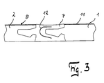
- Figure 3 shows another embodiment of a connecting element 7, which is provided with an integrated metal clip 12.
- This metal clip 12 is embedded in the plastic during extrusion and serves to increase the spring force of the connecting element 7.
- the bracket 12 is bent to substantially correspond to the enlarged circumferential contour of the groove 4a and the spring 3, respectively.
Landscapes
- Engineering & Computer Science (AREA)
- Architecture (AREA)
- Civil Engineering (AREA)
- Structural Engineering (AREA)
- Floor Finish (AREA)
- Piezo-Electric Or Mechanical Vibrators, Or Delay Or Filter Circuits (AREA)
- Surgical Instruments (AREA)
- Crystals, And After-Treatments Of Crystals (AREA)
- Wire Bonding (AREA)
Abstract
Description
- Die Erfindung betrifft ein Verbindungselement zum Verbinden von Bodenpaneelen mit einem Kern aus Holzwerkstoff, insbesondere MDF oder HDF, das an einer Seitenkante mit einer Feder und an der gegenüberliegenden Seitenkante mit einer Nut versehen ist, und die Feder zu der Nut des Paneels und die Nut zu der Feder des Paneels korrespondiert.
- Eine solches Verbindungselement zur Verbindung von Bodenpaneelen ist beispielsweise aus der
DE 101 62 275 C1 bekannt. Das Verbindungselement ist streifenförmig ausgeführt und wird über eine Feder mit der Nut des Paneels bzw. über eine Nut mit der Feder des Paneels verbunden. - Die Oberseite des Verbindungselements schließt mit der Oberseite des Paneels ab. Sie kann unterschiedlich geformt sein und im Querschnitt konvexe, konkave oder V-förmige Oberflächenkonturen aufweisen. Bei der Verbindung von Verbindungselement und Fußbodenpaneel ergibt sich ein Stoß zwischen der Paneelkante und der Kante des Verbindungselements. Durch diese Stöße bilden sich zwischen den Paneelkanten und den Kanten des Verbindungselements sehr schmale, mit bloßem Auge nicht sichtbare, vertikal gerichtete Fugen aus. Gerade beim feuchten Wischen eines Fußbodens wirkt sich diese Tatsache besonders nachteilig aus, da die Stoßfuge wie eine Kapillare wirkt, die die Feuchtigkeit zwischen Paneel und Verbindungselement hineinzieht.
- Bodenpaneele bestehen vorrangig aus Holzwerkstoffen, wie beispielsweise HDF/MDF oder OSB. Da durch die Kapillarwirkung Feuchtigkeit in den Holzwerkstoffkern der Fußbodenpaneele eindringen kann, quellen die betroffenen Seitenkanten der Paneele auf und bilden einen in der Fläche sichtbaren Überstand, eine so genannte Aufstippung. Durch diese Aufstippung wird die Qualität des Fußbodens erheblich gemindert.
- Von dieser Problemstellung ausgehend soll das eingangs beschriebene Verbindungselement dahingehend verbessert werden, dass das Aufquellen der Seitenkanten verbundener Fußbodenpaneele verhindert wird.
- Zur Problemlösung zeichnet sich ein gattungsgemäßes Verbindungselement dadurch aus, dass an der Oberseite zwei gegenüberliegende über die Seitenkanten hinausragende Lippen ausgebildet sind.
- Durch diese Ausgestaltung werden die bei der Verbindung von Verbindungselement und Fußbodenpaneel entstehenden Stöße überlappt, wodurch vorteilhafter Weise zwischen den angrenzenden Seitenkanten von Verbindungselement und Paneel eine dichte Abdeckung entsteht. Zur Sicherstellung der Wasserdichtheit besitzen die überlappenden Lippen eine genügend große Eigenelastizität, die das äußere Lippenende gegen die Paneeloberseite bzw. die Dekoroberseite zwingt. Die Oberseite des Fußbodenpaneels ist dabei mit einer Dekoroberfläche versehen, die einen natürlichen Werkstoff imitieren kann und den Kernwerkstoff vor Beschädigungen, z.B. durch Feuchte oder Abrieb, schützt.
- Vorteilhafterweise kann auf der Unterseite der überlappenden Lippen eine Beflockung vorgesehen sein, um die abdichtende Wirkung der Lippen noch zu erhöhen. Vorteilhafterweise sind die Flockfasern senkrecht auf der Trägerfläche, hier der Unterseite der überlappenden Lippen, angeordnet, um über eine entsprechend dichte Anordnung von Fasern je Flächeninhalt einen verbesserten Schutz gegen das Eindringen von Feuchtigkeit von oben in die Verbindung sicherzustellen.
- Die Verbindungselemente können aus einem Materialgemisch aus Holzfasern und Kunststoff hergestellt werden. Auf diese Weise lassen sich kostengünstige Verbindungselemente erstellen, die aufgrund des Holzfaseranteils holzähnliche Eigenschaften aufweisen. Die Verbindungselemente können im Durchlaufverfahren als Extrusionsprofil hergestellt werden, wobei das Beflocken der Unterseite der überlappenden Lippen zweckmäßigerweise gleichfalls im Durchlauf unter Ausnutzung der dem Verbindungselement am Ende der Extrusion innewohnenden Wärmeenergie erfolgt. Dadurch kann auf eine separate Kleberschicht zur innigen Verbindung von Verbindungselement und Flockfaser verzichtet werden. Vorzugsweise können die Verbindungselemente auch vollständig aus Kunststoff ausgebildet werden. Dem Material der Verbindungselemente sind Farbpigmente beigebbar, um das Verbindungselement einzufärben und so entsprechend an unterschiedliche Anforderungen bezüglich des Dekors der Paneele anzupassen.
- Vorzugsweise sind die Lippen elastisch federnd ausgebildet, damit eine möglichst gute Abdichtung der Stöße zwischen Verbindungselement und Paneele erreicht werden kann. Dazu ist es erforderlich, dass die Lippen bei der Verbindung zweier Paneele auf der Oberseite der Paneele dichtend aufliegen. Auf diese Weise kann verhindert werden, dass bei der feuchten Reinigung des Fußbodens Wasser in die Stoßfugen zwischen Verbindungselement und Paneele eindringen kann und zur Aufquellung des Fußbodens und zu Aufstippungen führt.
- Im Bereich der Nut und der Feder des Verbindungselements sowie in den korrespondierenden Bereichen der Nut und der Federn der Paneele können mechanische Verriegelungsmittel vorgesehen sein, die verbundene Paneele in Querrichtung verriegeln, ohne dass eine Leimzugabe in die Nuten bzw. Federn erforderlich ist. Auf diese Weise kann eine besonders einfache und schnelle Verlegung der Fußbodenpaneele und der Verbindungselemente erreicht werden.
- Zur Erhöhung der Federkraft kann in das Verbindungselement eine vorzugsweise aus Metall bestehende Klammer einextrudiert werden, die so gebogen sein kann, dass sie im Wesentlichen der Umfangskontur der Nut entspricht.
- Mit Hilfe einer Zeichnung sollen Ausführungsbeispiele der Erfindung nachfolgend näher erläutert werden. Es zeigen:
- Figur 1 -
- zwei über ein Verbindungselement miteinander verbundene Fußbodenpaneele an der Verbindungsstelle in Teilansicht;
- Figur 2 -
- eine Ausschnittsvergrößerung aus Figur 1 mit einer hervorragenden Lippe;
- Figur 3 -
- zwei über ein weiteres Verbindungselement miteinander verbundene Fußbodenpaneele an der Verbindungsstelle in Teilansicht.
- Die Fußbodenpaneele 1, 2 bestehen aus einer mitteldichten oder hoch verdichteten Faserplatte, z.B. MDF bzw. HDF. An ihrer Oberseite 8 sind sie mit einer Dekorschicht 11 versehen, die beispielsweise durch eine eine Holzmaserung oder eine Natursteinoberfläche imitierende Papierlage oder einen entsprechenden Direktdruck gebildet sein kann, die mit einer als Verschleißschutz dienenden Kunstharzschicht überzogen ist. An den sich gegenüberliegenden Seitenkanten I, II ist jedes Paneel 1, 2 mit einer Feder 3 und einer Nut 4 versehen. Die Feder 3 korrespondiert zu der auf der gegenüberliegenden Seite eingefrästen Nut 4. Das Paneel 2 ist im Bereich der Nut 4 mit einem Verriegelungsmittel 6 versehen, das mit einem an der Unterseite der Feder 3 des Paneels 1 vorgesehenen Verriegelungsmittel 5 zusammenwirkt und die verbundenen Paneelen 1, 2 miteinander verrasten können, so dass die verbundenen Paneele 1, 2 quer zur Verbindungsrichtung verriegelt sind.
- Wenn an der Oberseite 8 der Fußbodenpaneele zwischen zwei Paneelen 1, 2 eine sichtbare Verbindungsstelle, beispielsweise eine Sichtfuge erzeugt werden soll, ist das Verbindungselement 7 vorgesehen, das streifenförmig ausgebildet ist und an den Seitenkanten Ia, IIa eine Nut 4a bzw. eine Feder 3a aufweist. Die Feder 3a ist an ihrer Unterseite mit einem Verriegelungsmittel 5a versehen. Die Nut 4a weist im unteren Bereich ein Verriegelungsmittel 6a auf. Die Ausbildung der Feder 3a mit ihrem Verriegelungsmittel 5a und die Ausbildung der Nut 4a mit ihrem Verriegelungsmittel 6a des Verbindungselements 7 entspricht der Ausbildung der Feder 3 mit ihrem Verriegelungsmittel 5 bzw. der Nut 4 mit ihrem Verriegelungsmittel 6 der Paneele 1, 2. Das Verbindungselement 7 passt sich also nahtlos an die Verbindung zweier Paneele 1, 2 an. An der Oberseite 10 des Verbindungselements 7 ist im Bereich der Seitenkanten Ia, IIa je eine Lippe 9 ausgebildet, die auf der Oberseite 8 der Paneele 1, 2 aufliegen und den Stoß zwischen den Paneelen 1, 2 und dem Verbindungselement 7 überlappen, um so das Eindringen von Feuchtigkeit in den Stoß zwischen Fußbodenpaneel 2 und Verbindungselement 7 zu verhindern. Die Lippen 9 weisen auf ihrer Unterseite 9a eine Beflockung mit Flockfasern auf, die senkrecht auf der Unterseite 9a der überlappenden Lippen 9 angeordnet sind und eine dichte Anordnung von Fasern je Flächeneinheit ausbilden und so einen verbesserten Schutz gegen das Eindringen von Feuchtigkeit von oben in den Holzwerkstoffkern des Fußbodenpaneels 1 oder 2 bewirken.
- Figur 3 zeigt ein weiteres Ausführungsbeispiel eines Verbindungselementes 7, das mit einer integrierten Metallklammer 12 versehen ist. Diese Metallklammer 12 wird während des Extrudierens in den Kunststoff eingebettet und dient dazu, die Federkraft des Verbindungselementes 7 zu erhöhen. Die Klammer 12 ist so gebogen, dass sie im Wesentlichen der vergrößerten Umfangskontur der Nut 4a bzw. der Feder 3 entspricht.
-
- 1
- Paneel
- 2
- Paneel
- 3
- Feder
- 3a
- Feder
- 4
- Nut
- 4a
- Nut
- 5
- Verriegelungsmittel
- 5a
- Verriegelungsmittel
- 6
- Verriegelungsmittel
- 6a
- Verriegelungsmittel
- 7
- Verbindungselement
- 8
- Oberseite
- 9
- Lippe
- 9a
- Unterseite
- 10
- Oberseite
- 11
- Dekorschicht
- 12
- Klammer
- I
- Seitenkante
- Ia
- Seitenkante
- II
- Seitenkante
- IIa
- Seitenkante
Claims (11)
- Verbindungselement zum Verbinden von Bodenpaneelen (1, 2) mit einem Kern aus Holzwerkstoff, insbesondere MDF oder HDF, das an einer Seitenkante (Ia) mit einer Feder (3a) und an der gegenüberliegenden Seitenkante (IIa) mit einer Nut (4a) versehen ist, und die Feder (3a) zu der Nut (4) des Paneels (1, 2) und die Nut (4a) zu der Feder (3) des Paneels (1, 2) korrespondiert, dadurch gekennzeichnet, dass an der Oberseite (10) zwei gegenüberliegende, über die Seitenkanten (Ia, IIa) hinausragende Lippen (9) ausgebildet sind.
- Verbindungselement nach Anspruch 1, dadurch gekennzeichnet, dass die Lippen (9) elastisch federnd sind.
- Verbindungselement nach Anspruch 1 oder 2, dadurch gekennzeichnet, dass die Lippen (9) bei Verbindung zweier Paneele (1, 2) auf der Oberseite (8) der Paneele (1, 2) dichtend aufliegen.
- Verbindungselement nach Anspruch 3, dadurch gekennzeichnet, dass die Lippen (9) auf ihrer Unterseite (9a) eine Beflockung aufweisen.
- Verbindungselement nach einem oder mehreren der vorstehenden Ansprüche, dadurch gekennzeichnet, dass es aus einer Mischung aus Holzfasern und Kunststoff besteht.
- Verbindungselement nach einem oder mehreren der vorstehenden Ansprüche, dadurch gekennzeichnet, dass es aus Kunststoff besteht.
- Verbindungselement nach einem oder mehreren der vorstehenden Ansprüche, dadurch gekennzeichnet, dass es im Bereich der Nut (4a) und der Feder (3a) Verriegelungsmittel (5a, 6a) aufweist, die zu Verriegelungsmitteln (5, 6) der Feder (3) und der Nut (4) des Paneels (1, 2) korrespondieren.
- Verbindungselement nach einem oder mehreren der vorstehenden Ansprüche, gekennzeichnet durch eine eingelegte Klammer (12),
- Verbindungselement nach Anspruch 8, dadurch gekennzeichnet, dass die Klammer (12) gebogen ist und über die volle Länge reicht.
- Verbindungselement nach Anspruch 9, dadurch gekennzeichnet, dass die Klammer (12) im Wesentlichen der vergrößerten Umfangskontur der Nut (4a) entspricht,
- Verbindungselement nach einem oder mehreren der Ansprüche 8 bis 10, dadurch gekennzeichnet, dass die Klammer (12) aus Metall besteht.
Priority Applications (1)
| Application Number | Priority Date | Filing Date | Title |
|---|---|---|---|
| PL06019455T PL1767724T3 (pl) | 2005-09-22 | 2006-09-18 | Element łączący |
Applications Claiming Priority (1)
| Application Number | Priority Date | Filing Date | Title |
|---|---|---|---|
| DE102005045261A DE102005045261B3 (de) | 2005-09-22 | 2005-09-22 | Verbindungselement |
Publications (2)
| Publication Number | Publication Date |
|---|---|
| EP1767724A1 true EP1767724A1 (de) | 2007-03-28 |
| EP1767724B1 EP1767724B1 (de) | 2009-03-25 |
Family
ID=37496618
Family Applications (1)
| Application Number | Title | Priority Date | Filing Date |
|---|---|---|---|
| EP06019455A Not-in-force EP1767724B1 (de) | 2005-09-22 | 2006-09-18 | Verbindungselement |
Country Status (5)
| Country | Link |
|---|---|
| US (1) | US20070094985A1 (de) |
| EP (1) | EP1767724B1 (de) |
| AT (1) | ATE426713T1 (de) |
| DE (2) | DE102005045261B3 (de) |
| PL (1) | PL1767724T3 (de) |
Cited By (6)
| Publication number | Priority date | Publication date | Assignee | Title |
|---|---|---|---|---|
| WO2009127977A1 (en) * | 2008-04-16 | 2009-10-22 | Flooring Industries Limited, Sarl | Floor panels, floor covering composed thereof, and method for manufacturing such floor panels |
| EP2487309A1 (de) * | 2011-02-11 | 2012-08-15 | Barlinek S.A. | Baupaneele mit Hakenverbindung |
| CN102635217A (zh) * | 2012-01-16 | 2012-08-15 | 巴洛克木业(中山)有限公司 | 一种带定向刨花板的自由安装地板及其制造方法 |
| CN104675074A (zh) * | 2015-02-13 | 2015-06-03 | 安徽森泰塑木新材料有限公司 | 一种地板联接件 |
| CN104675075A (zh) * | 2015-02-13 | 2015-06-03 | 安徽森泰塑木新材料有限公司 | 一种用于承接并安装地板的底座 |
| CN104695681A (zh) * | 2015-02-13 | 2015-06-10 | 安徽森泰塑木新材料有限公司 | 一种地板系统 |
Families Citing this family (22)
| Publication number | Priority date | Publication date | Assignee | Title |
|---|---|---|---|---|
| SE533410C2 (sv) | 2006-07-11 | 2010-09-14 | Vaelinge Innovation Ab | Golvpaneler med mekaniska låssystem med en flexibel och förskjutbar tunga samt tunga därför |
| US11725394B2 (en) | 2006-11-15 | 2023-08-15 | Välinge Innovation AB | Mechanical locking of floor panels with vertical folding |
| US8689512B2 (en) | 2006-11-15 | 2014-04-08 | Valinge Innovation Ab | Mechanical locking of floor panels with vertical folding |
| SE531111C2 (sv) | 2006-12-08 | 2008-12-23 | Vaelinge Innovation Ab | Mekanisk låsning av golvpaneler |
| AU2010361006B2 (en) * | 2010-09-23 | 2014-06-12 | Flooring Technologies Ltd. | Method for producing panels and panel produced according to the method |
| US9725912B2 (en) | 2011-07-11 | 2017-08-08 | Ceraloc Innovation Ab | Mechanical locking system for floor panels |
| US8857126B2 (en) | 2011-08-15 | 2014-10-14 | Valinge Flooring Technology Ab | Mechanical locking system for floor panels |
| US9149115B2 (en) | 2012-06-16 | 2015-10-06 | Stact Wine Displays Inc. | Bottle rack and kit for bottle-supporting assembly |
| US8919068B2 (en) | 2012-07-05 | 2014-12-30 | Pergo (Europe) Ab | Devices, systems, and methods for exterior flooring |
| US9624677B2 (en) | 2012-07-05 | 2017-04-18 | Pergo (Europe) Ab | Joint devices, systems, and methods for exterior flooring |
| EP3014034B1 (de) | 2013-06-27 | 2019-10-02 | Välinge Innovation AB | Bauplatte mit einem mechanischen arretierungssystem |
| CN107002411B (zh) | 2014-11-27 | 2020-06-16 | 瓦林格创新股份有限公司 | 用于地板镶板的机械锁定系统 |
| USD821831S1 (en) | 2015-03-24 | 2018-07-03 | Stact Wine Displays Inc. | Bottle rack |
| US10004330B1 (en) | 2016-12-23 | 2018-06-26 | Stact Wine Displays Inc. | Bottle rack |
| USD848802S1 (en) | 2017-01-04 | 2019-05-21 | Stact Wine Displays Inc. | Bottle rack |
| USD834900S1 (en) | 2017-01-04 | 2018-12-04 | Stact Wine Displays Inc. | Bottle rack |
| USD923987S1 (en) | 2017-11-13 | 2021-07-06 | Stact Wine Displays Inc. | Bottle racks |
| USD878828S1 (en) | 2017-11-13 | 2020-03-24 | Stact Wine Displays Inc. | Bottle rack |
| US10941606B1 (en) | 2018-09-06 | 2021-03-09 | Endura Products, Llc | Connector system, apparatus and methods for a door frame assembly |
| US11060302B2 (en) | 2019-01-10 | 2021-07-13 | Valinge Innovation Ab | Unlocking system for panels |
| US12480357B2 (en) | 2021-05-04 | 2025-11-25 | Endura Products, Llc | Door stile with composite edge banding and method of manufacturing the same |
| USD1092161S1 (en) | 2023-09-22 | 2025-09-09 | Stact Wine Displays Inc. | Bottle rack |
Citations (8)
| Publication number | Priority date | Publication date | Assignee | Title |
|---|---|---|---|---|
| US1723306A (en) * | 1927-08-02 | 1929-08-06 | Harry E Sipe | Resilient attaching strip |
| US2779979A (en) * | 1953-03-16 | 1957-02-05 | Barclay Mfg Co Inc | Wall and wall unit construction |
| US3604169A (en) * | 1969-06-02 | 1971-09-14 | J D Distributing Co | Sealing strips |
| EP0313485A1 (de) * | 1987-10-23 | 1989-04-26 | Ab-Tec | Deckplatte für einen Doppelboden |
| US6336300B1 (en) * | 1999-01-12 | 2002-01-08 | Fred M. Babucke | Device to divert water from deck |
| FR2812899A1 (fr) * | 2000-08-10 | 2002-02-15 | Jean Philippe Drucar | Joint en matiere plastique extrudee permettant l'assemblage etanche et demontable de planches avec rainures adaptees |
| DE10162275C1 (de) * | 2001-12-19 | 2003-02-20 | Thomas Grafenauer | Einrichtung zum Verbinden von Bodenpaneelen |
| NL1027256C1 (nl) * | 2004-10-15 | 2006-04-19 | Houtindustrie Schijndel B V | Plankverbinding. |
Family Cites Families (28)
| Publication number | Priority date | Publication date | Assignee | Title |
|---|---|---|---|---|
| US1867312A (en) * | 1930-09-05 | 1932-07-12 | Reid Products Company | Channel |
| US2021922A (en) * | 1933-05-23 | 1935-11-26 | American Cyanamid & Chem Corp | Metal edged slab and building construction |
| US2004193A (en) * | 1934-12-05 | 1935-06-11 | Lug Lox Flooring Company | Board of the tongue and groove type |
| GB724919A (en) * | 1952-01-26 | 1955-02-23 | Rene Auguste Brosseau | Improvements in or relating to flooring |
| US2982380A (en) * | 1958-09-22 | 1961-05-02 | Rose Morton Jessup | Connecting means for building structures |
| US3182767A (en) * | 1960-05-04 | 1965-05-11 | Fiat Metal Mfg Co Inc | Shower cabinet construction |
| GB1068621A (en) * | 1964-03-19 | 1967-05-10 | B H Technical Developments Ltd | Improvements in or relating to roofs,walls and like structures |
| GB1285253A (en) * | 1969-09-03 | 1972-08-16 | Rehau Plastiks | Joint packing strip |
| US3690038A (en) * | 1970-11-16 | 1972-09-12 | Standard Products Co | Recessed weather strip body |
| GB1551056A (en) * | 1976-04-26 | 1979-08-22 | Draftex Dev Ag | Channel shaped sealing guiding or finishing strips and the like |
| DK149498C (da) * | 1983-04-07 | 1986-12-01 | Inter Ikea As | Beklaedning af braedder til f.eks. gulve eller paneler |
| US4869945A (en) * | 1988-05-09 | 1989-09-26 | General Motors Corporation | Weatherstrip carrier |
| US5072569A (en) * | 1990-08-13 | 1991-12-17 | Vantassel James | Building panels and method thereof |
| US5295341A (en) * | 1992-07-10 | 1994-03-22 | Nikken Seattle, Inc. | Snap-together flooring system |
| SE503917C2 (sv) * | 1995-01-30 | 1996-09-30 | Golvabia Ab | Anordning för sammanfogning medelst not och spånt av angränsande stycken av golvbeläggningsmaterial samt ett golvbeläggningsmaterial sammansatt av ett antal mindre stycken |
| US6421970B1 (en) * | 1995-03-07 | 2002-07-23 | Perstorp Flooring Ab | Flooring panel or wall panel and use thereof |
| US5791113A (en) * | 1996-06-28 | 1998-08-11 | Inkster Park Millwork Ltd. | Structural connecting and sealing member |
| AT405560B (de) * | 1997-06-18 | 1999-09-27 | Kaindl M | Anordnung mit bauteilen und bauteile |
| IT237576Y1 (it) * | 1997-07-11 | 2000-09-13 | Unifor Spa | Sistema di collegamento perfezionato tra pannelli componibili |
| US6079160A (en) * | 1998-01-13 | 2000-06-27 | Arrowhead Industries Corporation | Core metal insert with stagger and offset backbone |
| US6344268B1 (en) * | 1998-04-03 | 2002-02-05 | Certainteed Corporation | Foamed polymer-fiber composite |
| CA2287561C (en) * | 1998-10-26 | 2007-08-28 | Faroex Ltd. | Structural panel for bridging between spaced support |
| US6286841B1 (en) * | 1998-12-30 | 2001-09-11 | Schlegel Corporation | Weather seal with reservoir structure |
| US6682811B1 (en) * | 1999-04-16 | 2004-01-27 | Magna International Of America, Inc. | Reinforced profile extrusion articles and method for making the same |
| US6363677B1 (en) * | 2000-04-10 | 2002-04-02 | Mannington Mills, Inc. | Surface covering system and methods of installing same |
| GB2362415B (en) * | 2000-05-15 | 2004-08-25 | Draftex Ind Ltd | Sealing,trimming and finishing strips and vehicle doors incorporating such strips |
| SE525661C2 (sv) * | 2002-03-20 | 2005-03-29 | Vaelinge Innovation Ab | System för bildande av dekorativa fogpartier och golvskivor därför |
| US8850769B2 (en) * | 2002-04-15 | 2014-10-07 | Valinge Innovation Ab | Floorboards for floating floors |
-
2005
- 2005-09-22 DE DE102005045261A patent/DE102005045261B3/de not_active Expired - Fee Related
-
2006
- 2006-09-18 DE DE502006003240T patent/DE502006003240D1/de active Active
- 2006-09-18 AT AT06019455T patent/ATE426713T1/de active
- 2006-09-18 PL PL06019455T patent/PL1767724T3/pl unknown
- 2006-09-18 EP EP06019455A patent/EP1767724B1/de not_active Not-in-force
- 2006-09-20 US US11/533,634 patent/US20070094985A1/en not_active Abandoned
Patent Citations (8)
| Publication number | Priority date | Publication date | Assignee | Title |
|---|---|---|---|---|
| US1723306A (en) * | 1927-08-02 | 1929-08-06 | Harry E Sipe | Resilient attaching strip |
| US2779979A (en) * | 1953-03-16 | 1957-02-05 | Barclay Mfg Co Inc | Wall and wall unit construction |
| US3604169A (en) * | 1969-06-02 | 1971-09-14 | J D Distributing Co | Sealing strips |
| EP0313485A1 (de) * | 1987-10-23 | 1989-04-26 | Ab-Tec | Deckplatte für einen Doppelboden |
| US6336300B1 (en) * | 1999-01-12 | 2002-01-08 | Fred M. Babucke | Device to divert water from deck |
| FR2812899A1 (fr) * | 2000-08-10 | 2002-02-15 | Jean Philippe Drucar | Joint en matiere plastique extrudee permettant l'assemblage etanche et demontable de planches avec rainures adaptees |
| DE10162275C1 (de) * | 2001-12-19 | 2003-02-20 | Thomas Grafenauer | Einrichtung zum Verbinden von Bodenpaneelen |
| NL1027256C1 (nl) * | 2004-10-15 | 2006-04-19 | Houtindustrie Schijndel B V | Plankverbinding. |
Cited By (9)
| Publication number | Priority date | Publication date | Assignee | Title |
|---|---|---|---|---|
| WO2009127977A1 (en) * | 2008-04-16 | 2009-10-22 | Flooring Industries Limited, Sarl | Floor panels, floor covering composed thereof, and method for manufacturing such floor panels |
| US9151062B2 (en) | 2008-04-16 | 2015-10-06 | Flooring Industries Limited, Sarl | Floor panels, floor covering composed thereof, and method for manufacturing such floor panels |
| EP2487309A1 (de) * | 2011-02-11 | 2012-08-15 | Barlinek S.A. | Baupaneele mit Hakenverbindung |
| CN102635217A (zh) * | 2012-01-16 | 2012-08-15 | 巴洛克木业(中山)有限公司 | 一种带定向刨花板的自由安装地板及其制造方法 |
| CN104675074A (zh) * | 2015-02-13 | 2015-06-03 | 安徽森泰塑木新材料有限公司 | 一种地板联接件 |
| CN104675075A (zh) * | 2015-02-13 | 2015-06-03 | 安徽森泰塑木新材料有限公司 | 一种用于承接并安装地板的底座 |
| CN104695681A (zh) * | 2015-02-13 | 2015-06-10 | 安徽森泰塑木新材料有限公司 | 一种地板系统 |
| CN104695681B (zh) * | 2015-02-13 | 2017-06-16 | 安徽森泰塑木新材料有限公司 | 一种地板系统 |
| CN104675074B (zh) * | 2015-02-13 | 2017-06-16 | 安徽森泰塑木新材料有限公司 | 一种地板联接件 |
Also Published As
| Publication number | Publication date |
|---|---|
| DE502006003240D1 (de) | 2009-05-07 |
| US20070094985A1 (en) | 2007-05-03 |
| DE102005045261B3 (de) | 2007-05-03 |
| ATE426713T1 (de) | 2009-04-15 |
| PL1767724T3 (pl) | 2009-08-31 |
| EP1767724B1 (de) | 2009-03-25 |
Similar Documents
| Publication | Publication Date | Title |
|---|---|---|
| EP1767724B1 (de) | Verbindungselement | |
| DE60213161T2 (de) | Bodenbelagelement mit Dichtungsring | |
| DE102012104930B4 (de) | Parkettdiele | |
| EP3708739B1 (de) | Hartes fussbodenpaneel zur schwimmenden verlegung unter ausbildung eines fussbodenpaneelverbundes | |
| DE202004021957U1 (de) | Verbindungsmittel | |
| DE20222019U1 (de) | Bodenpaneele mit Versiegelung | |
| DE19962830A1 (de) | Verbindung | |
| DE102011121348A1 (de) | Paneel eines Fußbodenbelags mit einer entlang einer Seitenkante geneigten Verriegelungsfläche | |
| DE60213360T2 (de) | Fussbodensystem mit Fussbodenplatten und Verfahren zur Verbindung derartiger Platten | |
| DE10232508C1 (de) | Fussbodenpaneel | |
| DE202019101603U1 (de) | Lösbare Verbindung von Baupaneelen zur Montage eines Mosaik-Flächenbelags | |
| DE10162275C1 (de) | Einrichtung zum Verbinden von Bodenpaneelen | |
| DE19951812C2 (de) | Boden- oder Wandbelag | |
| EP2441592B1 (de) | Parkettdiele | |
| DE202015100159U1 (de) | Plattenförmiges Bauelement, insbesondere Fußbodenpaneel | |
| DE19925865C2 (de) | Parkettlamelle, sowie hieraus hergestelltes Parkettelement und Verfahren zur Herstellung eines Fussbodenpaneels | |
| EP0884172A2 (de) | Flächenbelagelement und Flächenbelag, insbesondere Bodenbelagelement oder Wandbelagelement, und Verfahren hierzu | |
| DE69307006T2 (de) | Fussbodenplatte aus einem mehrschichtigen tragenden Paneel, auf dessen Oberfläche ein massiver Holzstreifen aufgebracht ist und das aus einer Struktur aus hölzenen und nicht-hölzernen Materialschichten besteht | |
| DE102006008147A1 (de) | Verfahren zum Herstellen eines Paneelelementes sowie ein Paneelelement zur Ausbildung eines Fußboden-, Wand- oder Deckenbelags | |
| DE102005030780A1 (de) | Balkon- und Terrassenboden | |
| EP0134250B1 (de) | Vorrichtung zur Herstellung von gepressten Profilkörpern | |
| AT507961B1 (de) | Parkettelement für boden-, wand- oder deckenbelag | |
| EP4446517A1 (de) | Fussbodenbelag aus in ihrem aufbau identischen paneelen und paneel | |
| DE102004040723A1 (de) | Einrichtung zum Verbinden von Bauplatten | |
| AT328161B (de) | Fertigparkettelement |
Legal Events
| Date | Code | Title | Description |
|---|---|---|---|
| PUAI | Public reference made under article 153(3) epc to a published international application that has entered the european phase |
Free format text: ORIGINAL CODE: 0009012 |
|
| AK | Designated contracting states |
Kind code of ref document: A1 Designated state(s): AT BE BG CH CY CZ DE DK EE ES FI FR GB GR HU IE IS IT LI LT LU LV MC NL PL PT RO SE SI SK TR |
|
| AX | Request for extension of the european patent |
Extension state: AL BA HR MK YU |
|
| 17P | Request for examination filed |
Effective date: 20070926 |
|
| AKX | Designation fees paid |
Designated state(s): AT BE BG CH CY CZ DE DK EE ES FI FR GB GR HU IE IS IT LI LT LU LV MC NL PL PT RO SE SI SK TR |
|
| 17Q | First examination report despatched |
Effective date: 20080125 |
|
| GRAP | Despatch of communication of intention to grant a patent |
Free format text: ORIGINAL CODE: EPIDOSNIGR1 |
|
| GRAS | Grant fee paid |
Free format text: ORIGINAL CODE: EPIDOSNIGR3 |
|
| GRAA | (expected) grant |
Free format text: ORIGINAL CODE: 0009210 |
|
| AK | Designated contracting states |
Kind code of ref document: B1 Designated state(s): AT BE BG CH CY CZ DE DK EE ES FI FR GB GR HU IE IS IT LI LT LU LV MC NL PL PT RO SE SI SK TR |
|
| REG | Reference to a national code |
Ref country code: GB Ref legal event code: FG4D Free format text: NOT ENGLISH |
|
| REG | Reference to a national code |
Ref country code: CH Ref legal event code: EP |
|
| REG | Reference to a national code |
Ref country code: IE Ref legal event code: FG4D Free format text: LANGUAGE OF EP DOCUMENT: GERMAN |
|
| REG | Reference to a national code |
Ref country code: CH Ref legal event code: NV Representative=s name: BRAUNPAT BRAUN EDER AG |
|
| REF | Corresponds to: |
Ref document number: 502006003240 Country of ref document: DE Date of ref document: 20090507 Kind code of ref document: P |
|
| PG25 | Lapsed in a contracting state [announced via postgrant information from national office to epo] |
Ref country code: FI Free format text: LAPSE BECAUSE OF FAILURE TO SUBMIT A TRANSLATION OF THE DESCRIPTION OR TO PAY THE FEE WITHIN THE PRESCRIBED TIME-LIMIT Effective date: 20090325 Ref country code: SI Free format text: LAPSE BECAUSE OF FAILURE TO SUBMIT A TRANSLATION OF THE DESCRIPTION OR TO PAY THE FEE WITHIN THE PRESCRIBED TIME-LIMIT Effective date: 20090325 Ref country code: LT Free format text: LAPSE BECAUSE OF FAILURE TO SUBMIT A TRANSLATION OF THE DESCRIPTION OR TO PAY THE FEE WITHIN THE PRESCRIBED TIME-LIMIT Effective date: 20090325 |
|
| PG25 | Lapsed in a contracting state [announced via postgrant information from national office to epo] |
Ref country code: SE Free format text: LAPSE BECAUSE OF FAILURE TO SUBMIT A TRANSLATION OF THE DESCRIPTION OR TO PAY THE FEE WITHIN THE PRESCRIBED TIME-LIMIT Effective date: 20090625 Ref country code: LV Free format text: LAPSE BECAUSE OF FAILURE TO SUBMIT A TRANSLATION OF THE DESCRIPTION OR TO PAY THE FEE WITHIN THE PRESCRIBED TIME-LIMIT Effective date: 20090325 |
|
| REG | Reference to a national code |
Ref country code: PL Ref legal event code: T3 |
|
| REG | Reference to a national code |
Ref country code: IE Ref legal event code: FD4D |
|
| PG25 | Lapsed in a contracting state [announced via postgrant information from national office to epo] |
Ref country code: CZ Free format text: LAPSE BECAUSE OF FAILURE TO SUBMIT A TRANSLATION OF THE DESCRIPTION OR TO PAY THE FEE WITHIN THE PRESCRIBED TIME-LIMIT Effective date: 20090325 Ref country code: EE Free format text: LAPSE BECAUSE OF FAILURE TO SUBMIT A TRANSLATION OF THE DESCRIPTION OR TO PAY THE FEE WITHIN THE PRESCRIBED TIME-LIMIT Effective date: 20090325 Ref country code: PT Free format text: LAPSE BECAUSE OF FAILURE TO SUBMIT A TRANSLATION OF THE DESCRIPTION OR TO PAY THE FEE WITHIN THE PRESCRIBED TIME-LIMIT Effective date: 20090901 Ref country code: ES Free format text: LAPSE BECAUSE OF FAILURE TO SUBMIT A TRANSLATION OF THE DESCRIPTION OR TO PAY THE FEE WITHIN THE PRESCRIBED TIME-LIMIT Effective date: 20090706 |
|
| PG25 | Lapsed in a contracting state [announced via postgrant information from national office to epo] |
Ref country code: IS Free format text: LAPSE BECAUSE OF FAILURE TO SUBMIT A TRANSLATION OF THE DESCRIPTION OR TO PAY THE FEE WITHIN THE PRESCRIBED TIME-LIMIT Effective date: 20090725 Ref country code: RO Free format text: LAPSE BECAUSE OF FAILURE TO SUBMIT A TRANSLATION OF THE DESCRIPTION OR TO PAY THE FEE WITHIN THE PRESCRIBED TIME-LIMIT Effective date: 20090325 Ref country code: SK Free format text: LAPSE BECAUSE OF FAILURE TO SUBMIT A TRANSLATION OF THE DESCRIPTION OR TO PAY THE FEE WITHIN THE PRESCRIBED TIME-LIMIT Effective date: 20090325 |
|
| PG25 | Lapsed in a contracting state [announced via postgrant information from national office to epo] |
Ref country code: DK Free format text: LAPSE BECAUSE OF FAILURE TO SUBMIT A TRANSLATION OF THE DESCRIPTION OR TO PAY THE FEE WITHIN THE PRESCRIBED TIME-LIMIT Effective date: 20090325 Ref country code: BG Free format text: LAPSE BECAUSE OF FAILURE TO SUBMIT A TRANSLATION OF THE DESCRIPTION OR TO PAY THE FEE WITHIN THE PRESCRIBED TIME-LIMIT Effective date: 20090625 Ref country code: IE Free format text: LAPSE BECAUSE OF FAILURE TO SUBMIT A TRANSLATION OF THE DESCRIPTION OR TO PAY THE FEE WITHIN THE PRESCRIBED TIME-LIMIT Effective date: 20090325 |
|
| PLBE | No opposition filed within time limit |
Free format text: ORIGINAL CODE: 0009261 |
|
| STAA | Information on the status of an ep patent application or granted ep patent |
Free format text: STATUS: NO OPPOSITION FILED WITHIN TIME LIMIT |
|
| 26N | No opposition filed |
Effective date: 20091229 |
|
| PG25 | Lapsed in a contracting state [announced via postgrant information from national office to epo] |
Ref country code: MC Free format text: LAPSE BECAUSE OF NON-PAYMENT OF DUE FEES Effective date: 20090930 |
|
| PG25 | Lapsed in a contracting state [announced via postgrant information from national office to epo] |
Ref country code: GR Free format text: LAPSE BECAUSE OF FAILURE TO SUBMIT A TRANSLATION OF THE DESCRIPTION OR TO PAY THE FEE WITHIN THE PRESCRIBED TIME-LIMIT Effective date: 20090626 |
|
| PG25 | Lapsed in a contracting state [announced via postgrant information from national office to epo] |
Ref country code: IT Free format text: LAPSE BECAUSE OF FAILURE TO SUBMIT A TRANSLATION OF THE DESCRIPTION OR TO PAY THE FEE WITHIN THE PRESCRIBED TIME-LIMIT Effective date: 20090325 |
|
| PG25 | Lapsed in a contracting state [announced via postgrant information from national office to epo] |
Ref country code: LU Free format text: LAPSE BECAUSE OF NON-PAYMENT OF DUE FEES Effective date: 20090918 |
|
| PG25 | Lapsed in a contracting state [announced via postgrant information from national office to epo] |
Ref country code: HU Free format text: LAPSE BECAUSE OF FAILURE TO SUBMIT A TRANSLATION OF THE DESCRIPTION OR TO PAY THE FEE WITHIN THE PRESCRIBED TIME-LIMIT Effective date: 20090926 |
|
| PG25 | Lapsed in a contracting state [announced via postgrant information from national office to epo] |
Ref country code: TR Free format text: LAPSE BECAUSE OF FAILURE TO SUBMIT A TRANSLATION OF THE DESCRIPTION OR TO PAY THE FEE WITHIN THE PRESCRIBED TIME-LIMIT Effective date: 20090325 |
|
| PG25 | Lapsed in a contracting state [announced via postgrant information from national office to epo] |
Ref country code: CY Free format text: LAPSE BECAUSE OF FAILURE TO SUBMIT A TRANSLATION OF THE DESCRIPTION OR TO PAY THE FEE WITHIN THE PRESCRIBED TIME-LIMIT Effective date: 20090325 |
|
| REG | Reference to a national code |
Ref country code: DE Ref legal event code: R082 Ref document number: 502006003240 Country of ref document: DE Representative=s name: GRAMM, LINS & PARTNER PATENT- UND RECHTSANWAEL, DE |
|
| REG | Reference to a national code |
Ref country code: FR Ref legal event code: PLFP Year of fee payment: 11 |
|
| REG | Reference to a national code |
Ref country code: FR Ref legal event code: PLFP Year of fee payment: 12 |
|
| REG | Reference to a national code |
Ref country code: DE Ref legal event code: R082 Ref document number: 502006003240 Country of ref document: DE Representative=s name: GRAMM, LINS & PARTNER PATENT- UND RECHTSANWAEL, DE Ref country code: DE Ref legal event code: R081 Ref document number: 502006003240 Country of ref document: DE Owner name: FLOORING TECHNOLOGIES LTD., MT Free format text: FORMER OWNER: FLOORING TECHNOLOGIES LTD., PIETA, MT |
|
| REG | Reference to a national code |
Ref country code: CH Ref legal event code: PCOW Free format text: NEW ADDRESS: SMARTCITY MALTA SCM01, OFFICE 406, RICASOLI, KALKARA SCM 1001 (MT) |
|
| REG | Reference to a national code |
Ref country code: BE Ref legal event code: PD Owner name: FLOORING TECHNOLOGIES LTD.; MT Free format text: DETAILS ASSIGNMENT: CHANGE OF OWNER(S), AUTRE, ADRESSE; FORMER OWNER NAME: FLOORING TECHNOLOGIES LTD. Effective date: 20170921 |
|
| REG | Reference to a national code |
Ref country code: CH Ref legal event code: PCAR Free format text: NEW ADDRESS: HOLEESTRASSE 87, 4054 BASEL (CH) |
|
| REG | Reference to a national code |
Ref country code: FR Ref legal event code: PLFP Year of fee payment: 13 |
|
| PGFP | Annual fee paid to national office [announced via postgrant information from national office to epo] |
Ref country code: AT Payment date: 20180918 Year of fee payment: 13 |
|
| PGFP | Annual fee paid to national office [announced via postgrant information from national office to epo] |
Ref country code: FR Payment date: 20190923 Year of fee payment: 14 |
|
| PGFP | Annual fee paid to national office [announced via postgrant information from national office to epo] |
Ref country code: PL Payment date: 20190904 Year of fee payment: 14 |
|
| PGFP | Annual fee paid to national office [announced via postgrant information from national office to epo] |
Ref country code: GB Payment date: 20190924 Year of fee payment: 14 |
|
| PGFP | Annual fee paid to national office [announced via postgrant information from national office to epo] |
Ref country code: DE Payment date: 20190927 Year of fee payment: 14 Ref country code: CH Payment date: 20190924 Year of fee payment: 14 |
|
| REG | Reference to a national code |
Ref country code: NL Ref legal event code: MM Effective date: 20191001 |
|
| PG25 | Lapsed in a contracting state [announced via postgrant information from national office to epo] |
Ref country code: NL Free format text: LAPSE BECAUSE OF NON-PAYMENT OF DUE FEES Effective date: 20191001 |
|
| REG | Reference to a national code |
Ref country code: BE Ref legal event code: MM Effective date: 20190930 |
|
| REG | Reference to a national code |
Ref country code: AT Ref legal event code: MM01 Ref document number: 426713 Country of ref document: AT Kind code of ref document: T Effective date: 20190918 |
|
| PG25 | Lapsed in a contracting state [announced via postgrant information from national office to epo] |
Ref country code: BE Free format text: LAPSE BECAUSE OF NON-PAYMENT OF DUE FEES Effective date: 20190930 |
|
| PG25 | Lapsed in a contracting state [announced via postgrant information from national office to epo] |
Ref country code: AT Free format text: LAPSE BECAUSE OF NON-PAYMENT OF DUE FEES Effective date: 20190918 |
|
| REG | Reference to a national code |
Ref country code: DE Ref legal event code: R119 Ref document number: 502006003240 Country of ref document: DE |
|
| REG | Reference to a national code |
Ref country code: CH Ref legal event code: PL |
|
| GBPC | Gb: european patent ceased through non-payment of renewal fee |
Effective date: 20200918 |
|
| PG25 | Lapsed in a contracting state [announced via postgrant information from national office to epo] |
Ref country code: DE Free format text: LAPSE BECAUSE OF NON-PAYMENT OF DUE FEES Effective date: 20210401 Ref country code: FR Free format text: LAPSE BECAUSE OF NON-PAYMENT OF DUE FEES Effective date: 20200930 |
|
| PG25 | Lapsed in a contracting state [announced via postgrant information from national office to epo] |
Ref country code: CH Free format text: LAPSE BECAUSE OF NON-PAYMENT OF DUE FEES Effective date: 20200930 Ref country code: LI Free format text: LAPSE BECAUSE OF NON-PAYMENT OF DUE FEES Effective date: 20200930 Ref country code: GB Free format text: LAPSE BECAUSE OF NON-PAYMENT OF DUE FEES Effective date: 20200918 |
|
| PG25 | Lapsed in a contracting state [announced via postgrant information from national office to epo] |
Ref country code: PL Free format text: LAPSE BECAUSE OF NON-PAYMENT OF DUE FEES Effective date: 20200918 |