EP1766254B1 - Steueralgorithmus mit geschlossener schleife für übertragung auf ventilbasis - Google Patents
Steueralgorithmus mit geschlossener schleife für übertragung auf ventilbasis Download PDFInfo
- Publication number
- EP1766254B1 EP1766254B1 EP05765055A EP05765055A EP1766254B1 EP 1766254 B1 EP1766254 B1 EP 1766254B1 EP 05765055 A EP05765055 A EP 05765055A EP 05765055 A EP05765055 A EP 05765055A EP 1766254 B1 EP1766254 B1 EP 1766254B1
- Authority
- EP
- European Patent Office
- Prior art keywords
- valve
- pressure
- transmission
- proportional
- control
- Prior art date
- Legal status (The legal status is an assumption and is not a legal conclusion. Google has not performed a legal analysis and makes no representation as to the accuracy of the status listed.)
- Expired - Lifetime
Links
Images


Classifications
-
- F—MECHANICAL ENGINEERING; LIGHTING; HEATING; WEAPONS; BLASTING
- F16—ENGINEERING ELEMENTS AND UNITS; GENERAL MEASURES FOR PRODUCING AND MAINTAINING EFFECTIVE FUNCTIONING OF MACHINES OR INSTALLATIONS; THERMAL INSULATION IN GENERAL
- F16H—GEARING
- F16H61/00—Control functions within control units of change-speed- or reversing-gearings for conveying rotary motion ; Control of exclusively fluid gearing, friction gearing, gearings with endless flexible members or other particular types of gearing
- F16H61/04—Smoothing ratio shift
-
- F—MECHANICAL ENGINEERING; LIGHTING; HEATING; WEAPONS; BLASTING
- F16—ENGINEERING ELEMENTS AND UNITS; GENERAL MEASURES FOR PRODUCING AND MAINTAINING EFFECTIVE FUNCTIONING OF MACHINES OR INSTALLATIONS; THERMAL INSULATION IN GENERAL
- F16D—COUPLINGS FOR TRANSMITTING ROTATION; CLUTCHES; BRAKES
- F16D48/00—External control of clutches
- F16D48/06—Control by electric or electronic means, e.g. of fluid pressure
- F16D48/066—Control of fluid pressure, e.g. using an accumulator
-
- F—MECHANICAL ENGINEERING; LIGHTING; HEATING; WEAPONS; BLASTING
- F16—ENGINEERING ELEMENTS AND UNITS; GENERAL MEASURES FOR PRODUCING AND MAINTAINING EFFECTIVE FUNCTIONING OF MACHINES OR INSTALLATIONS; THERMAL INSULATION IN GENERAL
- F16D—COUPLINGS FOR TRANSMITTING ROTATION; CLUTCHES; BRAKES
- F16D48/00—External control of clutches
- F16D48/06—Control by electric or electronic means, e.g. of fluid pressure
-
- F—MECHANICAL ENGINEERING; LIGHTING; HEATING; WEAPONS; BLASTING
- F16—ENGINEERING ELEMENTS AND UNITS; GENERAL MEASURES FOR PRODUCING AND MAINTAINING EFFECTIVE FUNCTIONING OF MACHINES OR INSTALLATIONS; THERMAL INSULATION IN GENERAL
- F16H—GEARING
- F16H61/00—Control functions within control units of change-speed- or reversing-gearings for conveying rotary motion ; Control of exclusively fluid gearing, friction gearing, gearings with endless flexible members or other particular types of gearing
-
- B—PERFORMING OPERATIONS; TRANSPORTING
- B60—VEHICLES IN GENERAL
- B60W—CONJOINT CONTROL OF VEHICLE SUB-UNITS OF DIFFERENT TYPE OR DIFFERENT FUNCTION; CONTROL SYSTEMS SPECIALLY ADAPTED FOR HYBRID VEHICLES; ROAD VEHICLE DRIVE CONTROL SYSTEMS FOR PURPOSES NOT RELATED TO THE CONTROL OF A PARTICULAR SUB-UNIT
- B60W50/00—Details of control systems for road vehicle drive control not related to the control of a particular sub-unit, e.g. process diagnostic or vehicle driver interfaces
- B60W2050/0001—Details of the control system
- B60W2050/0002—Automatic control, details of type of controller or control system architecture
- B60W2050/0008—Feedback, closed loop systems or details of feedback error signal
- B60W2050/0011—Proportional Integral Differential [PID] controller
-
- F—MECHANICAL ENGINEERING; LIGHTING; HEATING; WEAPONS; BLASTING
- F16—ENGINEERING ELEMENTS AND UNITS; GENERAL MEASURES FOR PRODUCING AND MAINTAINING EFFECTIVE FUNCTIONING OF MACHINES OR INSTALLATIONS; THERMAL INSULATION IN GENERAL
- F16D—COUPLINGS FOR TRANSMITTING ROTATION; CLUTCHES; BRAKES
- F16D2500/00—External control of clutches by electric or electronic means
- F16D2500/30—Signal inputs
- F16D2500/302—Signal inputs from the actuator
- F16D2500/3024—Pressure
-
- F—MECHANICAL ENGINEERING; LIGHTING; HEATING; WEAPONS; BLASTING
- F16—ENGINEERING ELEMENTS AND UNITS; GENERAL MEASURES FOR PRODUCING AND MAINTAINING EFFECTIVE FUNCTIONING OF MACHINES OR INSTALLATIONS; THERMAL INSULATION IN GENERAL
- F16D—COUPLINGS FOR TRANSMITTING ROTATION; CLUTCHES; BRAKES
- F16D2500/00—External control of clutches by electric or electronic means
- F16D2500/30—Signal inputs
- F16D2500/302—Signal inputs from the actuator
- F16D2500/3028—Voltage
-
- F—MECHANICAL ENGINEERING; LIGHTING; HEATING; WEAPONS; BLASTING
- F16—ENGINEERING ELEMENTS AND UNITS; GENERAL MEASURES FOR PRODUCING AND MAINTAINING EFFECTIVE FUNCTIONING OF MACHINES OR INSTALLATIONS; THERMAL INSULATION IN GENERAL
- F16D—COUPLINGS FOR TRANSMITTING ROTATION; CLUTCHES; BRAKES
- F16D2500/00—External control of clutches by electric or electronic means
- F16D2500/70—Details about the implementation of the control system
- F16D2500/704—Output parameters from the control unit; Target parameters to be controlled
- F16D2500/70402—Actuator parameters
- F16D2500/70406—Pressure
-
- F—MECHANICAL ENGINEERING; LIGHTING; HEATING; WEAPONS; BLASTING
- F16—ENGINEERING ELEMENTS AND UNITS; GENERAL MEASURES FOR PRODUCING AND MAINTAINING EFFECTIVE FUNCTIONING OF MACHINES OR INSTALLATIONS; THERMAL INSULATION IN GENERAL
- F16D—COUPLINGS FOR TRANSMITTING ROTATION; CLUTCHES; BRAKES
- F16D2500/00—External control of clutches by electric or electronic means
- F16D2500/70—Details about the implementation of the control system
- F16D2500/706—Strategy of control
- F16D2500/7061—Feed-back
- F16D2500/70615—PI control
-
- F—MECHANICAL ENGINEERING; LIGHTING; HEATING; WEAPONS; BLASTING
- F16—ENGINEERING ELEMENTS AND UNITS; GENERAL MEASURES FOR PRODUCING AND MAINTAINING EFFECTIVE FUNCTIONING OF MACHINES OR INSTALLATIONS; THERMAL INSULATION IN GENERAL
- F16D—COUPLINGS FOR TRANSMITTING ROTATION; CLUTCHES; BRAKES
- F16D2500/00—External control of clutches by electric or electronic means
- F16D2500/70—Details about the implementation of the control system
- F16D2500/706—Strategy of control
- F16D2500/7061—Feed-back
- F16D2500/70621—PD control
-
- F—MECHANICAL ENGINEERING; LIGHTING; HEATING; WEAPONS; BLASTING
- F16—ENGINEERING ELEMENTS AND UNITS; GENERAL MEASURES FOR PRODUCING AND MAINTAINING EFFECTIVE FUNCTIONING OF MACHINES OR INSTALLATIONS; THERMAL INSULATION IN GENERAL
- F16D—COUPLINGS FOR TRANSMITTING ROTATION; CLUTCHES; BRAKES
- F16D2500/00—External control of clutches by electric or electronic means
- F16D2500/70—Details about the implementation of the control system
- F16D2500/706—Strategy of control
- F16D2500/7061—Feed-back
- F16D2500/70626—PID control
-
- F—MECHANICAL ENGINEERING; LIGHTING; HEATING; WEAPONS; BLASTING
- F16—ENGINEERING ELEMENTS AND UNITS; GENERAL MEASURES FOR PRODUCING AND MAINTAINING EFFECTIVE FUNCTIONING OF MACHINES OR INSTALLATIONS; THERMAL INSULATION IN GENERAL
- F16D—COUPLINGS FOR TRANSMITTING ROTATION; CLUTCHES; BRAKES
- F16D2500/00—External control of clutches by electric or electronic means
- F16D2500/70—Details about the implementation of the control system
- F16D2500/706—Strategy of control
- F16D2500/70631—Feed-forward
-
- F—MECHANICAL ENGINEERING; LIGHTING; HEATING; WEAPONS; BLASTING
- F16—ENGINEERING ELEMENTS AND UNITS; GENERAL MEASURES FOR PRODUCING AND MAINTAINING EFFECTIVE FUNCTIONING OF MACHINES OR INSTALLATIONS; THERMAL INSULATION IN GENERAL
- F16D—COUPLINGS FOR TRANSMITTING ROTATION; CLUTCHES; BRAKES
- F16D2500/00—External control of clutches by electric or electronic means
- F16D2500/70—Details about the implementation of the control system
- F16D2500/71—Actions
- F16D2500/7107—Others
- F16D2500/7109—Pulsed signal; Generating or processing pulsed signals; PWM, width modulation, frequency or amplitude modulation
Definitions
- This invention relates to closed-loop pressure control of a valve, such as a valve in a vehicle transmission.
- present transmission control systems are not able to re-calibrate, or apply corrections to, their pre-programmed heuristic rules while in operation. That is, present transmission control systems may be characterized as "open loop" in that they provide input to a transmission but fail to take advantage of information that could be provided from the transmission system as output. Accordingly, there is a need for a transmission pressure control system that accounts for the non-linearity that exists in practically every such system. It would be further desirable in such a system to eliminate or significantly reduce steady state error.
- vehicle performance changes over time as vehicle parts, such as transmission parts, age and become worn.
- present transmission control systems are unable to calibrate the pressure applied in a clutch in a transmission to the present age and wear of the transmission.
- Present open loop systems simply are not capable of accounting for the wear and age of transmission parts.
- a transmission control system in a vehicle that applied an amount of pressure on a transmission clutch that was appropriate for the age and wear of the transmission.
- Such a transmission control system would have the benefits of improved fuel economy and better "drivability", i.e., the transmission would shift more smoothly than it would with a conventional open loop control system.
- Such a transmission control system would have the benefit of enabling parts in a transmission to accumulate less wear as they age.
- such a transmission control system would have the benefit of lowering the cost of parts in a transmission. This is because such parts would be required to have lower tolerances to fluctuations in pressure and other forces than today's transmission parts, thus lowering design and manufacturing costs.
- US Patent no. 4,947,970 describes a control system for a vehicle drive train including a controller which controls a clutch to control speed and acceleration, wherein the clutch is engaged by an actuating piston.
- a closed loop control is provided for control of the pressure applied to an inner portion of the actuating piston.
- the closed loop control comprises computing an error signal by subtracting a control signal which is proportional to the pressure applied to the inner piston portion from a clutch pressure setpoint signal, multiplying the resulting error signal with a proportional gain term which is based on an estimated value of line pressure, feeding the output from the multiplier through an lead/lag block and then through an integral lead block, and outputting the resulting output signal into a duty cycle conversion block to obtain a duty cycle control signal.
- US Patent no. 5,020,622 describes a feedback control system and method for controlling the wheel slip of a wheel driven by torque coupled through an electronically controlled hydraulically operable clutch from an internal combustion engine.
- the feedback control uses the sum of an error signal related to the wheel slip and a signal related to the pressure applied to the clutch as a feedback control signal for adjusting slipping of the clutch to reduce the wheel slip.
- Other feedback variables e.g. a derivative or an integral of the error signal, may also be derived from the error signal.
- a system for controlling pressure in a transmission comprises a transmission control unit, a valve controller that receives a desired pressure as input from the transmission control unit, a valve driver, a valve that regulates an amount of fluid in a transmission clutch, and a pressure transducer that reads a pressure in the transmission clutch and outputs a pressure reading to the valve controller, wherein the valve controller comprises logic for outputting to the valve driver an instruction for controlling the valve, the instruction being formulated using the desired pressure, the pressure reading and one of proportional-plus-integral control proportional-integral-derivative control, and proportional-derivative control, the desired pressure being input into a look-up table block, which uses a look-up table to determine a variable proportional gain used with respect to the one control.
- a method for controlling pressure in a transmission comprises receiving in a valve controller a desired pressure from a transmission control unit and outputting to a valve driver an instruction for controlling a valve in a transmission, the instruction being formulated using the desired pressure, a reading of an actual pressure in a transmission clutch, and one of proportional-plus-integral control, proportional-integral-derivative control, and proportional-derivative control, wherein the desired pressure is input into a a look-up table block, which uses a look-up table to determine a variable proportional gain, said variable proportional gain being used with respect to the one control.
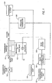
- transmission control unit 102 outputs to valve controller 104 a desired pressure for a transmission clutch 106.
- Valve controller 104 uses predetermined heuristic rules, instructs valve driver 108, an excitation driver capable of producing a desired voltage, to emit a certain voltage.
- the heuristic rules implemented in valve controller 104 comprise a variable gain control structure that is discussed in more detail below with reference to Figure 2 .
- transmission control unit 102 and valve controller 104 catch comprise at least one microprocessor.
- transmission control unit 102 and valve controller 104 are combined and together comprise one microprocessor.
- transmission control unit 102 will be one such as is presently known in the art, while valve controller 104 presents several novel features, including but by no means limited to, the capability of receiving as input information relating to the pressure state of a transmission clutch, and applying heuristic rules to instruct valve driver 108 to produce a certain voltage based at least in part on the afore-mentioned information.
- Solenoid 110 which receives voltage from valve driver 108, is a component of valve 112, which in turn is disposed within transmission manifold 114.
- Hydraulic fluid from transmission sump 116 is pumped via transmission pump 118 into transmission manifold 114 via supply port 120. Hydraulic fluid exits transmission manifold via control port 122.
- the state of valve 112 determines the quantity of hydraulic fluid that exits transmission manifold 114 in a given period of time from control port 122.
- the degree to which valve 112 is open or closed determines the quantity of hydraulic fluid that enters transmission clutch 126, i.e., the pressure that is applied to transmission clutch 126.
- valve 112 will be considered as “open” or “partially open” when all or some of the hydraulic fluid flowing through transmission manifold 114 is directed through control port 122.
- valve 112 will be considered as “closed” or “partially close” when none or some of the hydraulic fluid flowing through transmission manifold 114 is directed through control port 122.
- Pressure transducer 128, which is a transducer such as will be known to those skilled in the art, is disposed proximate to or within transmission clutch 106.
- Pressure transducer 128 provides input to valve controller 104, which bases its instruction to valve driver 108 at least in part an a determination of the present pressure within transmission clutch 106. That is, valve controller 104 receives as input from transmission control unit 102 a desired pressure value, and receives from pressure transducer 128 a measured pressure value.
- the objective of the control logic implemented in valve controller 104 discussed in more detail below with reference to Figure 2 , is to determine what adjustments to make to valve 112 in order to cause the measured pressure in transmission clutch 106 to equal or more closely approximate the desired pressure determined by transmission control unit 102.
- Valve 112 maybe any kind of proportional valve, such as a Variable Bleed Solenoid (VBS) valve, or a Variable Force Solenoid (VFS) valve. Valve 112 may also be a Pressure Width Modulation (PWM) valve. VBS, VFS, and PWM valves are all well known in the art. VBS and VFS valves are also know as proportional valves because they regulate pressure based on the valve being open or partially open. A PWM valve, by contrast, operates on a duty cycle that comprises a percentage of time within a period of time during which the valve is open. By opening and closing during the duty cycle, the PWM valve emulates the steady state behavior of the VBS valve. As is known, PWM valves are more efficient to operate, but require greater bandwidth.
- PWM valves are more efficient to operate, but require greater bandwidth.
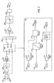
- FIG. 2 describes control logic that may be implemented in valve controller 104.
- the control logic of valve controller 104 uses proportional-plus-integral control, also known as proportional-integral, or PI, control.
- Proportional-plus-integral control will be known to those skilled in the art.
- Other embodiments of the invention use proportional-integral-derivative (PID), or proportional-derivative (PD), all of which are well known.
- PID proportional-integral-derivative
- PD proportional-derivative
- the control logic described herein is one that has been empirically shown to be effective in reducing or practically eliminating steady state error.
- Valve controller 104 receives as input two pressure values.
- P c 202 represents the desired pressure received from transmission controller 102, sometimes referred to as command pressure or control pressure.
- P T 204 represents a pressure reading from pressure transducer 128, that is, the actual pressure presently being exerted within transmission clutch 126.
- Block 206 calculates sampled error 208 by computing the difference between PC 202 and PT 204.
- Loop gain 209 applies a simple gain to the input to variable gain block 210. Those skilled in the art will recognize increasing the magnitude of loop gain 209 will reduce error by enabling greater precision in the calculations of variable gain block 210. Of course, it will also be understood that once the magnitude of loop gain 209 is increased past a certain point, the system may become unstable.
- Variable gain block 210 applies heuristic rules to produce an appropriate output from valve controller 104.
- Sampled error 208 is supplied as input 212 to proportional gain 213, which in turn provides input to multiplication block 214.
- Pc 202 is supplied as input 215 to look-up table block 216, which uses a look-up table to determine the value of a constant by which sampled-error 214 should be multiplied. Use of this look-up table achieves gain scheduling to compensate for valve non-linearity.
- the values in the lookup table can be empirically determined by noting what constant values corresponding to respective values of sampled error 208 result in the most accurate control of valve 112 with minimal response times.
- Block 214 multiplies sampled error 208 by the constant value determined in block 216 to produce output 218.
- Sampled error 208 is supplied as input 219 to integral gain 220, which multiplies sampled error 208 by a constant that has been empirically determined to result in the most accurate control of valve 112 with minima! response times.
- Discrete time integrator 222 integrates values for sampled error 208 as modified by interval gain 220 in order to produce output 224.
- Discrete-time integration will be known to those skilled in the art. In general, discrete time integrator 222 is reset only when a vehicle is turned off and then on again. In one practiced embodiment, the present invention uses the Trapezoidal method of discrete-time integration implemented in the SIMULINK software program.
- Output 218 and output 224 are summed in block 226, the result of this summation being amplified by loop gain 227 and then provided to saturation block 228. It is well known that, unless a capacitor is given adequate time to discharge, it may become “saturated” with voltage, meaning that further input to the capacitor will not have the intended effect, and means for limiting the effect of such saturation are also well known. Accordingly, those skilled in the art will understand that saturation block 228 determines what delay 230 is required before input is provided to valve driver 208.
- valve controller 104 After delay 230, valve controller 104 provides input 232 to valve driver 108.
- input 232 to valve driver 108 causes the valve 112 to be opened in the amount necessary to effect the desired pressure P C , 202 in transmission clutch 126.
- the input to valve driver 208 sets the duty cycle to a level appropriate to effect the desired pressure P C 202 in transmission clutch 126.
- Figures 3 and 4 are both graphs that illustrate that the inventive system very closely matches desired pressure P C 202 to the actual pressure P T 204 in transmission clutch 126.
- the present invention achieves many valuable advantages over the prior art.
- the present invention provides for improved wear of transmission parts by causing desired pressure P C 202 to be appropriate for the age and wear of parts in a vehicle transmission. While prior art open loop transmission control systems can accurately match desired pressure P C 202 and actual pressure P ⁇ 204 to within ten pounds per square inch (PSI), the present invention has been shown to have an accuracy of up to plus-or-minus two pounds PSI.
- PSI pounds per square inch
Landscapes
- Engineering & Computer Science (AREA)
- General Engineering & Computer Science (AREA)
- Physics & Mathematics (AREA)
- Fluid Mechanics (AREA)
- Mechanical Engineering (AREA)
- Control Of Transmission Device (AREA)
- Transition And Organic Metals Composition Catalysts For Addition Polymerization (AREA)
Claims (10)
- System zur Regelung des Drucks in einem Getriebe, das aufweist:eine Getriebesteuereinheit (102);eine Ventilregelungseinrichtung (104), die einen Drucksollwert (202) als Eingabe von der Getriebesteuereinheit (102) entgegennimmt;eine Ventilansteuerungseinrichtung (108);ein Ventil (112), das eine Menge eines Fluids in einer Getriebekupplung (106) regelt;und einen Druckgeber, der einen Druck in der Getriebekupplung (106) erfasst und einen Druckmesswert (204) zu der Ventilregelungseinrichtung (104) ausgibt;wobei die Ventilregelungseinrichtung (104) eine Logik zur Ausgabe einer Anweisung zur Steuerung des Ventils (112) zu der Ventilansteuerungseinrichtung (108) aufweist, wobei die Anweisung unter Verwendung des Drucksollwertes (202), des Druckmesswertes (204) und einer einzelnen von einer Proportional-Integral-Regelung, Proportional-Integral-Differential-Regelung und Proportional-Differential-Regelung formuliert ist, wobei der Drucksollwert (202) in einen Nachschlagetabellenblock (216) eingegeben wird, der eine Nachschlagetabelle verwendet, um einen variablen Proportionalverstärkungsfaktor zu bestimmen, der hinsichtlich der einen einzelnen Regelung verwendet wird.
- System nach Anspruch 1, wobei das Ventil (112) ein Pulsweitenmodulationsventil (PWM-Ventil) ist.
- System nach Anspruch 1, wobei das Ventil (112) ein Proportionalventil ist.
- System nach Anspruch 1, wobei die Ventilregelungseinrichtung (104) eine Logik zur Bestimmung, ob das System einen Sättigungspunkt erreicht hat, aufweist.
- System nach Anspruch 4, wobei der Sättigungspunkt eine maximale Höhe einer Spannung, die durch einen Kondensator erhalten werden kann, aufweist.
- Verfahren zur Regelung des Drucks in einem Getriebe, das aufweist:Empfangen eines Drucksollwertes (202) in einer Ventilregelungseinrichtung (104) von einer Getriebesteuereinheit (102); undAusgeben einer Anweisung zur Steuerung eines Ventils (112) in einem Getriebe an eine Ventilansteuerungseinrichtung (108), wobei die Anweisung unter Verwendung des Drucksollwertes (202), einer Ablesung eines Druckistwertes (204) in einer Getriebekupplung (106) und einer Regelung aus einer Proportional-Integral-Regelung, Proportional-Integral-Differential-Regelung und Proportional-Differential-Regelung formuliert ist, wobei der Drucksollwert (202) in einen Nachschlagetabellenblock (216) eingespeist wird, der eine Nachschlagetabelle verwendet, um einen hinsichtlich der einen Regelung verwendeten variablen Proportionalverstärkungsfaktor zu bestimmen.
- Verfahren nach Anspruch 6, wobei das Ventil (112) ein Pulsweitenmodulationsventil (PWM-Ventil) ist.
- Verfahren nach Anspruch 6, wobei das Ventil (112) ein Proportionalventil ist.
- Verfahren nach Anspruch 5, wobei die Ventilregelungseinrichtung (104) eine Logik zur Bestimmung, ob das System einen Sättigungspunkt erreicht hat, aufweist.
- Verfahren nach Anspruch 9, wobei der Sättigungspunkt eine maximale Höhe einer Spannung, die durch einen Kondensator erhalten werden kann, aufweist.
Applications Claiming Priority (2)
| Application Number | Priority Date | Filing Date | Title |
|---|---|---|---|
| US10/874,133 US7194349B2 (en) | 2004-06-22 | 2004-06-22 | Closed-loop, valve-based transmission control algorithum |
| PCT/IB2005/001625 WO2006000861A2 (en) | 2004-06-22 | 2005-06-10 | Closed-loop, valve-based transmission control algorithm |
Publications (2)
| Publication Number | Publication Date |
|---|---|
| EP1766254A2 EP1766254A2 (de) | 2007-03-28 |
| EP1766254B1 true EP1766254B1 (de) | 2009-05-20 |
Family
ID=35004228
Family Applications (1)
| Application Number | Title | Priority Date | Filing Date |
|---|---|---|---|
| EP05765055A Expired - Lifetime EP1766254B1 (de) | 2004-06-22 | 2005-06-10 | Steueralgorithmus mit geschlossener schleife für übertragung auf ventilbasis |
Country Status (12)
| Country | Link |
|---|---|
| US (1) | US7194349B2 (de) |
| EP (1) | EP1766254B1 (de) |
| JP (1) | JP2008503700A (de) |
| KR (1) | KR101182897B1 (de) |
| CN (1) | CN1973147B (de) |
| AT (1) | ATE431910T1 (de) |
| AU (1) | AU2005256902B2 (de) |
| BR (1) | BRPI0511340A (de) |
| CA (1) | CA2571838A1 (de) |
| DE (1) | DE602005014555D1 (de) |
| MX (1) | MXPA06015164A (de) |
| WO (1) | WO2006000861A2 (de) |
Families Citing this family (17)
| Publication number | Priority date | Publication date | Assignee | Title |
|---|---|---|---|---|
| US7484429B2 (en) * | 2005-05-10 | 2009-02-03 | Eaton Corporation | Closed loop adaptive fluid control system and method |
| US20070288148A1 (en) * | 2006-06-08 | 2007-12-13 | Weijia Cui | Adaptive Open Loop Line Pressure Control Of Hydraulic Fluid In An Automatic Transmission |
| US20080082242A1 (en) * | 2006-10-03 | 2008-04-03 | Dell Eva Mark L | Mode selection and switching logic in a closed-loop pulse width modulation valve-based transmission control system |
| DE102008009094B4 (de) * | 2008-02-14 | 2009-12-24 | Getrag Getriebe- Und Zahnradfabrik Hermann Hagenmeyer Gmbh & Cie Kg | Verfahren zum Ansteuern einer Kupplung |
| US8182238B2 (en) * | 2009-04-03 | 2012-05-22 | Ford Global Technologies, Llc | Variable displacement transmission pump control |
| US8092330B2 (en) * | 2009-09-18 | 2012-01-10 | Ford Global Technologies, Llc | Control for an automatic transmission |
| US8473170B2 (en) | 2010-09-17 | 2013-06-25 | Caterpillar Inc. | Closed loop transmission torque control |
| US8631919B2 (en) * | 2010-12-17 | 2014-01-21 | GM Global Technology Operations LLC | Automatic transmission shift quality via selective use of closed-loop pressure feedback control |
| US9284865B2 (en) * | 2012-01-11 | 2016-03-15 | Eaton Corporation | Method of controlling fluid pressure-actuated switching component and control system for same |
| BR112015023271A2 (pt) * | 2013-03-13 | 2017-07-18 | Dana Belgium Nv | método para calibrar uma embreagem úmida, a embreagem compreendendo uma bomba para prover a um alojamento um fluido hidráulico, um pistão disposto de maneira passível de movimento no alojamento, o pistão podendo se mover para uma posição estendida por meio de uma mola pré-carregada e para uma posição retraída ao se aplicar uma pressão de engrenamento no pistão por meio do fluido hidráulico, em que o torque de posição retraída pode ser transmitido por meio de embreagem, uma válvula proporcional disposta entre a bomba e o alojamento para regular uma pressão do fluido hidráulico no alojamento, um controlador controlando a válvula proporcional, um sensor de pressão para medir uma pressão do fluido hidráulico no alojamento e aparato para calibrar uma embreagem úmida. |
| EP3734102B1 (de) * | 2013-03-13 | 2022-01-12 | Eaton Corporation | System und verfahren zur kupplungsdrucksteuerung |
| US9565067B1 (en) * | 2014-02-20 | 2017-02-07 | The Mathworks, Inc. | Heterogeneous units management system with dimensionless, ambiguous, and partial units |
| EP3252349A1 (de) | 2016-05-30 | 2017-12-06 | Dana Belgium N.V. | Verfahren zum schalten eines fahrzeuggetriebes und antriebsstrang für kraftfahrzeug |
| EP3252336A1 (de) | 2016-05-30 | 2017-12-06 | Dana Belgium N.V. | Füllparametererlernung für nassplattenkupplungen auf basis einer ausgabe eines drehmomentwandlers |
| CN107575316B (zh) * | 2017-10-17 | 2019-07-09 | 杨青海 | 一种提高发动机燃油经济性的闭环控制方法 |
| DE102018115364A1 (de) * | 2018-06-26 | 2020-01-02 | Lsp Innovative Automotive Systems Gmbh | Vorrichtung zur Ansteuerung von mehreren Stellgliedern |
| CN110425275B (zh) * | 2019-07-26 | 2021-11-30 | 中国第一汽车股份有限公司 | 一种变速器换挡控制方法 |
Family Cites Families (21)
| Publication number | Priority date | Publication date | Assignee | Title |
|---|---|---|---|---|
| US3752011A (en) * | 1971-10-18 | 1973-08-14 | Gen Motors Corp | Method and apparatus for controlling a power transmission |
| US4611285A (en) * | 1984-04-05 | 1986-09-09 | Ford Motor Company | Method of controlling automatic transmission shift pressure |
| JPS6184446A (ja) * | 1984-09-29 | 1986-04-30 | Mitsubishi Motors Corp | 車両用自動変速機の制御装置 |
| DE3438594C2 (de) * | 1984-10-20 | 1994-01-20 | Fichtel & Sachs Ag | Kupplungseinrichtung für ein Kraftfahrzeug |
| JPS62159842A (ja) * | 1986-01-07 | 1987-07-15 | Toyota Motor Corp | 自動変速機の油圧制御装置 |
| DE3667836D1 (de) * | 1986-02-24 | 1990-02-01 | Shimadzu Corp | Hydromechanisches getriebe. |
| FR2616931B1 (fr) * | 1987-06-22 | 1989-10-06 | Renault | Dispositif de gestion d'une commande electro-hydraulique de pression |
| US5020622A (en) * | 1988-08-17 | 1991-06-04 | Ford Motor Company | Multiple feedback loop control method and system for controlling wheel slip |
| US4947970A (en) * | 1988-11-08 | 1990-08-14 | Borg-Warner Automotive, Inc. | Dual clutch control system |
| US5062050A (en) * | 1989-10-17 | 1991-10-29 | Borg-Warner Automotive, Inc. | Continuously variable transmission line pressure control |
| JPH0756333B2 (ja) * | 1989-10-19 | 1995-06-14 | マツダ株式会社 | 自動変速機の制御装置 |
| JPH05133469A (ja) * | 1991-11-11 | 1993-05-28 | Japan Electron Control Syst Co Ltd | 車両用自動変速機の制御装置 |
| US5400678A (en) * | 1992-10-30 | 1995-03-28 | Ford Motor Company | Line pressure optimization in an automatic transmission |
| KR100500721B1 (ko) * | 1996-03-14 | 2005-11-25 | 루크 게트리에베시스템 게엠베하 | 차량및제어방법 |
| KR100504061B1 (ko) * | 1998-03-19 | 2005-07-27 | 가부시키가이샤 히타치세이사쿠쇼 | 자동 변속기의 클러치 유압의 제어 장치와 제어 방법 |
| US6022293A (en) * | 1998-10-08 | 2000-02-08 | Chrysler Corporation | Electronic control of transmission line pressure |
| US6318182B1 (en) * | 1999-06-04 | 2001-11-20 | Eaton Corporation | Measurement of transmission oil pressure by monitoring solenoid current |
| US6253140B1 (en) * | 1999-08-04 | 2001-06-26 | Ford Global Technologies, Inc. | Engagement control logic for an automatic transmission clutch with adaptive engagement feel |
| US6381529B1 (en) * | 2001-06-07 | 2002-04-30 | Deere & Company | Control system for hydrostatic transmission |
| DE10145588A1 (de) * | 2001-09-15 | 2003-04-24 | Deere & Co | Verfahren und Vorrichtung zur Steuerung einer Kupplung |
| US6994647B2 (en) * | 2003-11-13 | 2006-02-07 | Ford Global Technologies, Llc | Adaptive pressure control method for achieving synchronous upshifts in a multiple-ratio transmission |
-
2004
- 2004-06-22 US US10/874,133 patent/US7194349B2/en not_active Expired - Lifetime
-
2005
- 2005-06-10 AU AU2005256902A patent/AU2005256902B2/en not_active Ceased
- 2005-06-10 KR KR1020067026965A patent/KR101182897B1/ko not_active Expired - Fee Related
- 2005-06-10 DE DE602005014555T patent/DE602005014555D1/de not_active Expired - Lifetime
- 2005-06-10 CN CN2005800206554A patent/CN1973147B/zh not_active Expired - Fee Related
- 2005-06-10 AT AT05765055T patent/ATE431910T1/de not_active IP Right Cessation
- 2005-06-10 CA CA002571838A patent/CA2571838A1/en not_active Abandoned
- 2005-06-10 WO PCT/IB2005/001625 patent/WO2006000861A2/en not_active Ceased
- 2005-06-10 EP EP05765055A patent/EP1766254B1/de not_active Expired - Lifetime
- 2005-06-10 MX MXPA06015164A patent/MXPA06015164A/es active IP Right Grant
- 2005-06-10 JP JP2007517507A patent/JP2008503700A/ja active Pending
- 2005-06-10 BR BRPI0511340-7A patent/BRPI0511340A/pt not_active IP Right Cessation
Also Published As
| Publication number | Publication date |
|---|---|
| JP2008503700A (ja) | 2008-02-07 |
| AU2005256902B2 (en) | 2011-05-19 |
| CA2571838A1 (en) | 2006-01-05 |
| CN1973147A (zh) | 2007-05-30 |
| MXPA06015164A (es) | 2007-11-07 |
| CN1973147B (zh) | 2011-01-12 |
| ATE431910T1 (de) | 2009-06-15 |
| AU2005256902A1 (en) | 2006-01-05 |
| US20050283297A1 (en) | 2005-12-22 |
| EP1766254A2 (de) | 2007-03-28 |
| US7194349B2 (en) | 2007-03-20 |
| KR101182897B1 (ko) | 2012-09-13 |
| WO2006000861A2 (en) | 2006-01-05 |
| BRPI0511340A (pt) | 2007-12-04 |
| WO2006000861A3 (en) | 2006-03-30 |
| KR20070031335A (ko) | 2007-03-19 |
| DE602005014555D1 (de) | 2009-07-02 |
Similar Documents
| Publication | Publication Date | Title |
|---|---|---|
| US7194349B2 (en) | Closed-loop, valve-based transmission control algorithum | |
| US4706790A (en) | Gain scheduling technique for a closed loop slip control system | |
| US4947970A (en) | Dual clutch control system | |
| US5719768A (en) | Lock-up clutch control method | |
| JP2007326556A (ja) | パラレルハイブリッド駆動経路の作動方法 | |
| JP2008215611A (ja) | 閉ループパルス幅変調弁伝達制御システムのモード選択およびスイッチングロジック | |
| KR101541194B1 (ko) | 자동 변속기의 유압 제어 장치 | |
| US20090183777A1 (en) | System and method for dynamic solenoid response adjust control | |
| US20080236539A1 (en) | Transmission clutch pressure controls via pilot pressure feedback | |
| US6101440A (en) | Controller for an automatic motor vehicle transmission | |
| KR101363903B1 (ko) | 무단 변속기의 라인압 제어 장치 | |
| CN101688495B (zh) | 用于适配调节流量调节阀的电阻值的方法 | |
| US6464603B1 (en) | Method and apparatus for controlling a transmission | |
| JP4124625B2 (ja) | 無段変速機の制御装置 | |
| US20070288148A1 (en) | Adaptive Open Loop Line Pressure Control Of Hydraulic Fluid In An Automatic Transmission | |
| JPH11294622A (ja) | ソレノイドバルブの駆動装置 | |
| JP2663675B2 (ja) | ロックアップクラッチの制御装置 | |
| JP3479211B2 (ja) | ソレノイド駆動装置 | |
| JP3423882B2 (ja) | ソレノイドバルブの駆動装置 | |
| CN107091321B (zh) | 用于确定液压泵的输送功率的方法和设备以及变速器 | |
| JPH0823389B2 (ja) | 自動変速機のロックアップ制御装置 | |
| JP2950872B2 (ja) | 無段変速機の制御装置 | |
| JP3197433B2 (ja) | ロックアップクラッチのスリップ制御装置 | |
| JP3481314B2 (ja) | 車両用制御装置 | |
| JPH01120479A (ja) | トルクコンバータのスリップ制御装置 |
Legal Events
| Date | Code | Title | Description |
|---|---|---|---|
| PUAI | Public reference made under article 153(3) epc to a published international application that has entered the european phase |
Free format text: ORIGINAL CODE: 0009012 |
|
| 17P | Request for examination filed |
Effective date: 20061213 |
|
| AK | Designated contracting states |
Kind code of ref document: A2 Designated state(s): AT BE BG CH CY CZ DE DK EE ES FI FR GB GR HU IE IS IT LI LT LU MC NL PL PT RO SE SI SK TR |
|
| 17Q | First examination report despatched |
Effective date: 20070419 |
|
| RIN1 | Information on inventor provided before grant (corrected) |
Inventor name: SURIANARAYANAN, ANANTHAKRISHNAN Inventor name: BARROWS, ERIC, O. Inventor name: SOSNOWSKI, DAVID R. Inventor name: JACOBSEN, PETER M. Inventor name: DELL'EVA, MARK L. |
|
| DAX | Request for extension of the european patent (deleted) | ||
| GRAP | Despatch of communication of intention to grant a patent |
Free format text: ORIGINAL CODE: EPIDOSNIGR1 |
|
| GRAS | Grant fee paid |
Free format text: ORIGINAL CODE: EPIDOSNIGR3 |
|
| GRAA | (expected) grant |
Free format text: ORIGINAL CODE: 0009210 |
|
| AK | Designated contracting states |
Kind code of ref document: B1 Designated state(s): AT BE BG CH CY CZ DE DK EE ES FI FR GB GR HU IE IS IT LI LT LU MC NL PL PT RO SE SI SK TR |
|
| REG | Reference to a national code |
Ref country code: GB Ref legal event code: FG4D |
|
| REG | Reference to a national code |
Ref country code: CH Ref legal event code: EP |
|
| REG | Reference to a national code |
Ref country code: IE Ref legal event code: FG4D |
|
| REF | Corresponds to: |
Ref document number: 602005014555 Country of ref document: DE Date of ref document: 20090702 Kind code of ref document: P |
|
| REG | Reference to a national code |
Ref country code: SE Ref legal event code: TRGR |
|
| PG25 | Lapsed in a contracting state [announced via postgrant information from national office to epo] |
Ref country code: PT Free format text: LAPSE BECAUSE OF FAILURE TO SUBMIT A TRANSLATION OF THE DESCRIPTION OR TO PAY THE FEE WITHIN THE PRESCRIBED TIME-LIMIT Effective date: 20090920 Ref country code: LT Free format text: LAPSE BECAUSE OF FAILURE TO SUBMIT A TRANSLATION OF THE DESCRIPTION OR TO PAY THE FEE WITHIN THE PRESCRIBED TIME-LIMIT Effective date: 20090520 Ref country code: FI Free format text: LAPSE BECAUSE OF FAILURE TO SUBMIT A TRANSLATION OF THE DESCRIPTION OR TO PAY THE FEE WITHIN THE PRESCRIBED TIME-LIMIT Effective date: 20090520 Ref country code: ES Free format text: LAPSE BECAUSE OF FAILURE TO SUBMIT A TRANSLATION OF THE DESCRIPTION OR TO PAY THE FEE WITHIN THE PRESCRIBED TIME-LIMIT Effective date: 20090831 Ref country code: AT Free format text: LAPSE BECAUSE OF FAILURE TO SUBMIT A TRANSLATION OF THE DESCRIPTION OR TO PAY THE FEE WITHIN THE PRESCRIBED TIME-LIMIT Effective date: 20090520 |
|
| NLV1 | Nl: lapsed or annulled due to failure to fulfill the requirements of art. 29p and 29m of the patents act | ||
| PG25 | Lapsed in a contracting state [announced via postgrant information from national office to epo] |
Ref country code: PL Free format text: LAPSE BECAUSE OF FAILURE TO SUBMIT A TRANSLATION OF THE DESCRIPTION OR TO PAY THE FEE WITHIN THE PRESCRIBED TIME-LIMIT Effective date: 20090520 Ref country code: NL Free format text: LAPSE BECAUSE OF FAILURE TO SUBMIT A TRANSLATION OF THE DESCRIPTION OR TO PAY THE FEE WITHIN THE PRESCRIBED TIME-LIMIT Effective date: 20090520 Ref country code: IS Free format text: LAPSE BECAUSE OF FAILURE TO SUBMIT A TRANSLATION OF THE DESCRIPTION OR TO PAY THE FEE WITHIN THE PRESCRIBED TIME-LIMIT Effective date: 20090920 Ref country code: SI Free format text: LAPSE BECAUSE OF FAILURE TO SUBMIT A TRANSLATION OF THE DESCRIPTION OR TO PAY THE FEE WITHIN THE PRESCRIBED TIME-LIMIT Effective date: 20090520 |
|
| PG25 | Lapsed in a contracting state [announced via postgrant information from national office to epo] |
Ref country code: CZ Free format text: LAPSE BECAUSE OF FAILURE TO SUBMIT A TRANSLATION OF THE DESCRIPTION OR TO PAY THE FEE WITHIN THE PRESCRIBED TIME-LIMIT Effective date: 20090520 Ref country code: DK Free format text: LAPSE BECAUSE OF FAILURE TO SUBMIT A TRANSLATION OF THE DESCRIPTION OR TO PAY THE FEE WITHIN THE PRESCRIBED TIME-LIMIT Effective date: 20090520 Ref country code: EE Free format text: LAPSE BECAUSE OF FAILURE TO SUBMIT A TRANSLATION OF THE DESCRIPTION OR TO PAY THE FEE WITHIN THE PRESCRIBED TIME-LIMIT Effective date: 20090520 Ref country code: MC Free format text: LAPSE BECAUSE OF NON-PAYMENT OF DUE FEES Effective date: 20090630 Ref country code: RO Free format text: LAPSE BECAUSE OF FAILURE TO SUBMIT A TRANSLATION OF THE DESCRIPTION OR TO PAY THE FEE WITHIN THE PRESCRIBED TIME-LIMIT Effective date: 20090520 |
|
| REG | Reference to a national code |
Ref country code: CH Ref legal event code: PL |
|
| PG25 | Lapsed in a contracting state [announced via postgrant information from national office to epo] |
Ref country code: BE Free format text: LAPSE BECAUSE OF FAILURE TO SUBMIT A TRANSLATION OF THE DESCRIPTION OR TO PAY THE FEE WITHIN THE PRESCRIBED TIME-LIMIT Effective date: 20090520 Ref country code: SK Free format text: LAPSE BECAUSE OF FAILURE TO SUBMIT A TRANSLATION OF THE DESCRIPTION OR TO PAY THE FEE WITHIN THE PRESCRIBED TIME-LIMIT Effective date: 20090520 |
|
| PLBE | No opposition filed within time limit |
Free format text: ORIGINAL CODE: 0009261 |
|
| STAA | Information on the status of an ep patent application or granted ep patent |
Free format text: STATUS: NO OPPOSITION FILED WITHIN TIME LIMIT |
|
| PG25 | Lapsed in a contracting state [announced via postgrant information from national office to epo] |
Ref country code: BG Free format text: LAPSE BECAUSE OF FAILURE TO SUBMIT A TRANSLATION OF THE DESCRIPTION OR TO PAY THE FEE WITHIN THE PRESCRIBED TIME-LIMIT Effective date: 20090820 |
|
| REG | Reference to a national code |
Ref country code: IE Ref legal event code: MM4A |
|
| 26N | No opposition filed |
Effective date: 20100223 |
|
| PG25 | Lapsed in a contracting state [announced via postgrant information from national office to epo] |
Ref country code: IE Free format text: LAPSE BECAUSE OF NON-PAYMENT OF DUE FEES Effective date: 20090610 Ref country code: LI Free format text: LAPSE BECAUSE OF NON-PAYMENT OF DUE FEES Effective date: 20090630 Ref country code: CH Free format text: LAPSE BECAUSE OF NON-PAYMENT OF DUE FEES Effective date: 20090630 |
|
| PG25 | Lapsed in a contracting state [announced via postgrant information from national office to epo] |
Ref country code: GR Free format text: LAPSE BECAUSE OF FAILURE TO SUBMIT A TRANSLATION OF THE DESCRIPTION OR TO PAY THE FEE WITHIN THE PRESCRIBED TIME-LIMIT Effective date: 20090821 |
|
| PG25 | Lapsed in a contracting state [announced via postgrant information from national office to epo] |
Ref country code: LU Free format text: LAPSE BECAUSE OF NON-PAYMENT OF DUE FEES Effective date: 20090610 |
|
| PG25 | Lapsed in a contracting state [announced via postgrant information from national office to epo] |
Ref country code: HU Free format text: LAPSE BECAUSE OF FAILURE TO SUBMIT A TRANSLATION OF THE DESCRIPTION OR TO PAY THE FEE WITHIN THE PRESCRIBED TIME-LIMIT Effective date: 20091121 |
|
| PG25 | Lapsed in a contracting state [announced via postgrant information from national office to epo] |
Ref country code: TR Free format text: LAPSE BECAUSE OF FAILURE TO SUBMIT A TRANSLATION OF THE DESCRIPTION OR TO PAY THE FEE WITHIN THE PRESCRIBED TIME-LIMIT Effective date: 20090520 |
|
| PG25 | Lapsed in a contracting state [announced via postgrant information from national office to epo] |
Ref country code: CY Free format text: LAPSE BECAUSE OF FAILURE TO SUBMIT A TRANSLATION OF THE DESCRIPTION OR TO PAY THE FEE WITHIN THE PRESCRIBED TIME-LIMIT Effective date: 20090520 |
|
| REG | Reference to a national code |
Ref country code: FR Ref legal event code: PLFP Year of fee payment: 12 |
|
| REG | Reference to a national code |
Ref country code: FR Ref legal event code: PLFP Year of fee payment: 13 |
|
| REG | Reference to a national code |
Ref country code: FR Ref legal event code: PLFP Year of fee payment: 14 |
|
| PGFP | Annual fee paid to national office [announced via postgrant information from national office to epo] |
Ref country code: IT Payment date: 20180523 Year of fee payment: 14 Ref country code: FR Payment date: 20180605 Year of fee payment: 14 |
|
| PGFP | Annual fee paid to national office [announced via postgrant information from national office to epo] |
Ref country code: SE Payment date: 20180525 Year of fee payment: 14 |
|
| PGFP | Annual fee paid to national office [announced via postgrant information from national office to epo] |
Ref country code: GB Payment date: 20180522 Year of fee payment: 14 |
|
| REG | Reference to a national code |
Ref country code: GB Ref legal event code: 732E Free format text: REGISTERED BETWEEN 20181115 AND 20181130 |
|
| REG | Reference to a national code |
Ref country code: DE Ref legal event code: R082 Ref document number: 602005014555 Country of ref document: DE Ref country code: DE Ref legal event code: R081 Ref document number: 602005014555 Country of ref document: DE Owner name: EATON INTELLIGENT POWER LIMITED, IE Free format text: FORMER OWNER: EATON CORP., CLEVELAND, OHIO, US |
|
| REG | Reference to a national code |
Ref country code: SE Ref legal event code: EUG |
|
| PG25 | Lapsed in a contracting state [announced via postgrant information from national office to epo] |
Ref country code: SE Free format text: LAPSE BECAUSE OF NON-PAYMENT OF DUE FEES Effective date: 20190611 |
|
| GBPC | Gb: european patent ceased through non-payment of renewal fee |
Effective date: 20190610 |
|
| PG25 | Lapsed in a contracting state [announced via postgrant information from national office to epo] |
Ref country code: GB Free format text: LAPSE BECAUSE OF NON-PAYMENT OF DUE FEES Effective date: 20190610 Ref country code: IT Free format text: LAPSE BECAUSE OF NON-PAYMENT OF DUE FEES Effective date: 20190610 |
|
| PG25 | Lapsed in a contracting state [announced via postgrant information from national office to epo] |
Ref country code: FR Free format text: LAPSE BECAUSE OF NON-PAYMENT OF DUE FEES Effective date: 20190630 |
|
| PGFP | Annual fee paid to national office [announced via postgrant information from national office to epo] |
Ref country code: DE Payment date: 20200519 Year of fee payment: 16 |
|
| REG | Reference to a national code |
Ref country code: DE Ref legal event code: R119 Ref document number: 602005014555 Country of ref document: DE |
|
| PG25 | Lapsed in a contracting state [announced via postgrant information from national office to epo] |
Ref country code: DE Free format text: LAPSE BECAUSE OF NON-PAYMENT OF DUE FEES Effective date: 20220101 |