EP1765445B1 - Katheter - Google Patents
Katheter Download PDFInfo
- Publication number
- EP1765445B1 EP1765445B1 EP05770761.4A EP05770761A EP1765445B1 EP 1765445 B1 EP1765445 B1 EP 1765445B1 EP 05770761 A EP05770761 A EP 05770761A EP 1765445 B1 EP1765445 B1 EP 1765445B1
- Authority
- EP
- European Patent Office
- Prior art keywords
- coil
- catheter
- tube
- inch
- sheath
- Prior art date
- Legal status (The legal status is an assumption and is not a legal conclusion. Google has not performed a legal analysis and makes no representation as to the accuracy of the status listed.)
- Not-in-force
Links
Images


Classifications
-
- A—HUMAN NECESSITIES
- A61—MEDICAL OR VETERINARY SCIENCE; HYGIENE
- A61F—FILTERS IMPLANTABLE INTO BLOOD VESSELS; PROSTHESES; DEVICES PROVIDING PATENCY TO, OR PREVENTING COLLAPSING OF, TUBULAR STRUCTURES OF THE BODY, e.g. STENTS; ORTHOPAEDIC, NURSING OR CONTRACEPTIVE DEVICES; FOMENTATION; TREATMENT OR PROTECTION OF EYES OR EARS; BANDAGES, DRESSINGS OR ABSORBENT PADS; FIRST-AID KITS
- A61F2/00—Filters implantable into blood vessels; Prostheses, i.e. artificial substitutes or replacements for parts of the body; Appliances for connecting them with the body; Devices providing patency to, or preventing collapsing of, tubular structures of the body, e.g. stents
- A61F2/95—Instruments specially adapted for placement or removal of stents or stent-grafts
-
- A—HUMAN NECESSITIES
- A61—MEDICAL OR VETERINARY SCIENCE; HYGIENE
- A61M—DEVICES FOR INTRODUCING MEDIA INTO, OR ONTO, THE BODY; DEVICES FOR TRANSDUCING BODY MEDIA OR FOR TAKING MEDIA FROM THE BODY; DEVICES FOR PRODUCING OR ENDING SLEEP OR STUPOR
- A61M25/00—Catheters; Hollow probes
- A61M25/0043—Catheters; Hollow probes characterised by structural features
- A61M25/005—Catheters; Hollow probes characterised by structural features with embedded materials for reinforcement, e.g. wires, coils, braids
-
- A—HUMAN NECESSITIES
- A61—MEDICAL OR VETERINARY SCIENCE; HYGIENE
- A61F—FILTERS IMPLANTABLE INTO BLOOD VESSELS; PROSTHESES; DEVICES PROVIDING PATENCY TO, OR PREVENTING COLLAPSING OF, TUBULAR STRUCTURES OF THE BODY, e.g. STENTS; ORTHOPAEDIC, NURSING OR CONTRACEPTIVE DEVICES; FOMENTATION; TREATMENT OR PROTECTION OF EYES OR EARS; BANDAGES, DRESSINGS OR ABSORBENT PADS; FIRST-AID KITS
- A61F2250/00—Special features of prostheses classified in groups A61F2/00 - A61F2/26 or A61F2/82 or A61F9/00 or A61F11/00 or subgroups thereof
- A61F2250/0014—Special features of prostheses classified in groups A61F2/00 - A61F2/26 or A61F2/82 or A61F9/00 or A61F11/00 or subgroups thereof having different values of a given property or geometrical feature, e.g. mechanical property or material property, at different locations within the same prosthesis
Definitions
- This invention relates to catheters, as well as related systems and methods.
- Such a catheter is disclosed in the WO 0147436 .
- Systems are known for delivering medical devices, such as stents, into a body lumen.
- a proximal portion typically includes a handle that is held by an operator of the system (e.g., a physician) during use, and the distal portion can include a sheath surrounding a catheter with a stent positioned therebetween.
- the operator of the system positions the distal portion within the lumen at a desired location (e.g., so that the stent is adjacent an occlusion). The operator can then retract the sheath to allow the stent to engage the occlusion/lumen wall. Thereafter, the operator removes the distal portion of the system from the lumen.
- the invention relates to a catheter as further disclosed in claim 1, as well as related systems and methods.
- the catheters can be used, for example, in implantable medical endoprosthesis delivery systems (e.g., stent delivery systems).
- the systems can be used, for example, to deliver a medical endoprosthesis (e.g., a stent) at a desired location within a lumen of a subject (e.g., an artery of a human).
- the catheters generally include a tube and a coil that at least partially surrounds the tube.
- the coil can include a first portion disposed inwardly of a second portion, where the first and second portions are made of different materials.
- the first portion of the coil can be in the form of a wire (e.g., a wire formed of a metal or alloy), and the second portion of the coil can be a polymer (e.g., a thermoplastic) coated on the wire.
- the tube and coil can be at least partially surrounded by a sheath (e.g., a sheath that is heat shrunk to the exposed surfaces of the tube and coil).
- the catheters can be sufficiently flexible for use in implantable medical endoprosthesis delivery systems while also having a relatively high compression resistance. This can, for example, allow the catheters to undergo little or no compression or buckling during deployment of a medical endoprosthesis (e.g., stent), which can enhance the precision of placement of the medical endoprosthesis (e.g., stent) during deployment.
- a medical endoprosthesis e.g., stent
- the catheters can be designed to allow good fluid flow between the catheter and a surrounding sheath, which can aid in delivery of the system to a desired site within a subject (e.g., a human) and/or deployment of the medical endoprosthesis (e.g., stent) at a desired site (e.g., an artery of a human).
- a subject e.g., a human
- the medical endoprosthesis e.g., stent
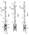
- FIGS. 1-3 show an implantable medical endoprosthesis delivery system 10 that includes a catheter 12, a sheath 14 surrounding catheter 12, and a stent 32 positioned between catheter 12 and sheath 14.
- the delivery system 10 includes a distal end 16 dimensioned for insertion into a body lumen (e.g., an artery of a human) and a proximal end 18 that resides outside the body of a subject, and that contains at least one port 50 and lumens for manipulation by a physician.
- a body lumen e.g., an artery of a human
- a guide wire 20 with a blunted end 22 is inserted into a body lumen 24 by, for example, making an incision in the femoral artery, and directing guide wire 20 to a constricted site 26 of lumen 24 (e.g., an artery constricted with plaque) using, for example, fluoroscopy as a position aid.
- a constricted site 26 of lumen 24 e.g., an artery constricted with plaque
- fluoroscopy as a position aid.
- catheter 12 stent 32 and sheath 14 are placed over the proximal end of guide wire 20.
- Catheter 12, stent 32 and sheath 14 are moved distally over guide wire 20 and positioned within lumen 24 so that stent 32 is adjacent constricted site 26 of lumen 24.
- Sheath 14 is moved proximally, allowing stent 32 to expand and engage constricted site 26.
- Sheath 14, catheter 12 and guide wire 20 are removed from body lumen 24, leaving s
- catheter 12 includes a tube 62 surrounded by a coil 64.
- Catheter 12 also includes a coating 72 that surrounds tube 62 and coil 64.
- Catheter 12 is dimensioned so that a space, S, is present between catheter 12 and sheath 14 (see FIG. 4 , area C).
- catheter 12 can exhibit enhanced compression resistance with little or no buckling of catheter 12 (e.g., as sheath 14 is retracted proximally). It is also believed that this configuration also allows for appropriate fluid flow between catheter 12 and sheath 14.
- Coil 64 includes an inner portion 68 that is surrounded by an outer portion 66.
- Inner portion 68 can be, for example, a wire formed of a metal, an alloy or a polymeric material.
- metals include platinum and gold.
- alloys include gold-containing alloys, platinum-containing alloys, stainless steel and shape memory alloys.
- shape memory alloys include nitinol, silver-cadmium (Ag-Cd), gold-cadmium (Au-Cd), gold-copper-zinc (Au-Cu-Zn), copper-aluminum-nickel (Cu-Al-Ni), copper-gold-zinc (Cu-Au-Zn), copper-zinc/(Cu-Zn), copper-zinc-aluminum (Cu-Zn-Al), copper-zinc-tin (Cu-Zn-Sn), copper-zinc-xenon (Cu-Zn-Xe), iron beryllium (Fe 3 Be), iron platinum (Fe 3 Pt), indium-thallium (In-Tl), iron-manganese (Fe-Mn), nickel-titanium-vanadium (Ni-Ti-V), iron-nickel-titanium-cobalt (Fe-Ni-Ti-Co) and copper-tin (Cu-Sn).
- polymeric materials include nylons, thermoplastic polyester elastomers (e.g., Hytrel ® ), copolyester elastomers (e.g., Arnitel ® copolyester elastomers), polyether-block co-polyamide polymers (e.g., PEBAX ® ) and high-density polyethylene (HDPEs).
- thermoplastic polyester elastomers e.g., Hytrel ®
- copolyester elastomers e.g., Arnitel ® copolyester elastomers
- polyether-block co-polyamide polymers e.g., PEBAX ®
- HDPEs high-density polyethylene
- Outer portion 66 can be, for example, a polymeric material, such as a plastic (e.g., a thermoplastic).
- polymeric materials include polyamides, polyurethanes, styrenic block copolymers, nylons, thermoplastic polyester elastomers (e.g., Hytrel ® ), copolyester elastomers (e.g., Arnitel ® copolyester elastomers), polyether-block co-polyamide polymers (e.g., PEBAX ® ) and HDPEs.
- outer portion 66 is integral with the outer surface of tube 62. This can, for example, assist in maintaining the position of coil 64 constant with respect to tube 62.
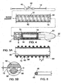
- Coil 64 is a helical coil with a pitch, P, (see FIG. 5A ) between, adjacent windings of, for example, from at least about 0,127 mm 0.005 inch) (e.g., at least about 0,254 mm 0.01 inch, at least about 1,27 mm 0.05 inch) and/or at most about 2,54 mm 0.1 inch (e.g., at most about 1,905 mm 0.075 inch, at most about 0,524 mm 0.06 inch).
- P pitch
- the pitch P of coil 64 is from about 0,127 mm 0.005 inch to about 0.1 (e.g., from about 0.254 mm 0.01 inch to about 1,524 mm 0.06 inch, from about 1,27 mm 0.05 inch to about 1,524 mm 0.06 inch).
- coil 64 is circular in cross-section with a diameter, D, (see FIG. 5B ) of at least about 0,0508 mm 0.002 inch (e.g., at least about 0,1016 mm 0.004 inch) and/or at most about 0,254 mm 0.01 (e.g., at most about 0,127 mm 0.005 inch).
- the diameter, D, of coil 64 can be from about 0,0508 mm 0.002 inch to about 0,254 mm 0.1 inch (e.g., from about 0,1016 mm 0.004 inch to about 0,152 mm 0.006 inch, about 0,127 mm 0.005 inch).
- coating 72 is made of a material that can be that can be bonded to the exposed outer surfaces of tube 62 and coil 64.
- materials include heat shrink materials and polymeric materials such as polyether-block co-polyamide polymers (e.g., PEBAX ® ) and nylons.
- heat shrink materials include cross-linked polyethylene, polyester (e.g., PET) heat shrink, fluorinated ethylene (FEP) heat shrink, polytetrafluoroethylene (PTFE) heat shrink.
- coating 72 includes an additive (e.g., a fluoropolymer, a silicone, an ultrahigh molecular weight polyethylene, an oil, or blends thereof) to assist in the movement of catheter 12 with respect to sheath 14 and stent 32.
- the thickness, T, of coating 72 is at least about 0,0254 mm 0.001 inch (e.g., at least about 0,0508 mm 0.002 inch) and/or at most about 0,254 mm 0.01 inch (e.g., at most about 0,2032 mm 0.008 inch).
- the thickness, T, of coating 72 is from about 0,0254 mm 0.001 inch to about 0,254 mm 0.01 inch (e.g., from about 0,0508 mm 0.002 inch to about 0,2032 mm 0.008 inch, about 0,1524 mm 0.006 inch).
- Stent 32 is typically formed of a shape memory alloy.
- shape memory alloys include those discussed above with respect to inner portion 68 of coil 64.
- tube 62 is made of a polymeric material.
- polymeric materials include polyether-block co-polyamide polymers (e.g., PEBAX ® ), copolyester elastomers (e.g., Arnitel ® copolyester elastomers), thermoplastic polyester elastomers (e.g., Hytrel ® ), thermoplastic polyurethane elastomers (e.g., PellethaneTM), polyeolefms (e.g., Marlex ® polyethylene, Marlex ® polypropylene), HDPEs, low-density polyethylenes (LDPEs), polyamides (e.g., Vestamid ® ), and combinations of these materials.
- PEBAX ® polyether-block co-polyamide polymers
- copolyester elastomers e.g., Arnitel ® copolyester elastomers
- thermoplastic polyester elastomers e.g.
- sheath 14 is made of a polymeric material.
- polymeric materials include those noted above with respect to tube 62.
- sheath 14 includes an additive (e.g., a fluoropolymer, a silicone, an ultrahigh molecular weight polyethylene, an oil, or blends thereof) to assist in the movement of sheath 14 with respect to catheter 12 and stent 32.
- an additive e.g., a fluoropolymer, a silicone, an ultrahigh molecular weight polyethylene, an oil, or blends thereof
- FIG. 4 shows that system 10 can further include a bumper 70 that is integral with tube 62, and a tip 61 that is integral with tube 62.
- Bumper 70 can reduce the possibility of stent 32 moving proximally as sheath 14 is retracted proximally, and tip 61 can assist in positioning of system 10 within body lumen 26 (e.g., as system 10 is moved distally over guide wire 20 within body lumen 24).
- bumper 70 is formed of a polymeric material, such as a polyether-block co-polyamide polymer (e.g., PEBAX ® ) or a thermoplastic polyurethane elastomer (e.g., PellethaneTM).
- bumper 70 is made of a metal or an alloy, such as, for example, stainless steel, Nitinol and/or platinum.
- Tip 61 is typically formed of a relatively soft polymeric material.
- catheter 12 can be prepared as desired. In some embodiments, catheter 12 can be prepared as follows.
- FIG. 7 illustrates an embodiment of a pultrusion process for a making a monofilament 100.
- a spool 112 of a metallic filament (e.g., stainless steel wire) 114 is pulled through a fluid polymeric material (e.g., molten thermoplastic) 116 that is pumped onto filament 114 by extruder 118 as filament 114 passes through a die 120 with an aperture 122. After exiting die 120, monofilament 100 is collected on a spool 101.
- Pultrusion processes are disclosed, for example, in U.S. Patent Nos.
- Equipment for performing pultrusion processes is commercially available from, for example, Entec Composite Machines, Salt Lake City, UT (USA) and Pultrex, Essex (UK).
- Monofilament 100 is formed into a coil.
- FIG. 8 shows an embodiment of a process for forming monofilament 100 into a coil by winding monofilament 100 around a mandrel 102 as mandrel 102 is rotated by a motor 132.
- Monofilament 100 is supplied to mandrel 102 via a main tension pulley 134 and a cantilevered pulley 136.
- mandrel 102 is several inches (e.g., about 50,8 mm two (inches)) longer than the desired coil length.
- Filament winding processes are disclosed, for example, in U.S. Patent Nos. 5,335,167 and 5,601,599 .
- Filament winding equipment is commercially available from, for example, Pultrex, Essex (UK). Wound monofilament 100 is removed from mandrel 102 to provide coil 64 (see FIG. 9 ).
- Tube 62 is placed around a support member, then coil 64 is placed around tube 62, and wound filament 100 is made integral with 62, thereby providing tube 62 surrounded by coil 64 (see discussion above).
- FIG. 10 shows tube 62 disposed around a support member 150. Support member 150 reduces the possibility of tube 62 during subsequent processing.
- coil 64 can be made integral with tube 62 by exposure to energy (e.g., heat, UV, IR).
- energy e.g., heat, UV, IR
- outer material 66 of coil 64 is a thermoplastic material, and coil 64 can be made integral with tube 62 by heating outer material 66 with a heat gun so that outer material 66 is welded to tube 62.
- FIG. 11 shows an embodiment in which a heat shrink tubing 152 is disposed around tube 62 and coil 64. Tubing 152 is then exposed to radiation (e.g., heat, UV, IR) to collapse tubing 152 and adhere it to the exposed outer surfaces of tube 62 and coil 64, thereby forming coating 72.
- radiation e.g., heat, UV, IR
- the implantable medical endoprosthesis can be a balloon-expandable implantable medical endoprostheses (e.g., a balloon-expandable stent).
- inner catheter 12 would typically include an expandable balloon in the region around which the implantable medical endoprostheses is exposed during delivery.
- Additional examples of implantable medical endoprostheses include stent-grafts and filters (e.g., arterial filters, venus filters).
- catheter 12 does not include coating 72.
- coil 64 may be formed of a single portion, or catheter 64 may be formed of more than two portions (e.g., three layers, four layers, five layers, six layers, seven layers, eight layers, nine layers, 10 layers).
- the portions can be in the shape of layers.
- coil 64 can have a noncircular transverse cross-section (e.g., half moon shaped transverse cross-section, rectangular transverse cross-section, hexagonal transverse cross-section, pentagonal transverse cross-section, octagonal transverse cross-section). This can be achieved, for example, by using a correspondingly shaped inner portion (e.g., a correspondingly shaped wire).
- the width of the transverse cross-section of inner portion 68 can be, for example, at least about 0,0254 mm 0.001 inch (e.g., at least about 0,1016 mm 0.004 inch) and/or at most about 0,254 mm 0.01 inch (e.g., at most about 0,2032 mm 0.008 inch), and the length of the transverse cross-section of inner portion 68 can be, for example, at least about 0,0254 mm 0.001 inch (e.g., at least about 0,1016 mm 0.004 inch) and/or at most about 1,27 mm 0.05 inch (e.g., at most about 0,762 mm 0.03 inch).
- the transverse cross-section of inner portion 68 can be at least about 0,0254 mm 0.001 inch (e.g., at least about 0,1016 mm 0.004 inch) and/or at most about 0,762 mm 0.03 inch (e.g., at most about 0,254 mm 0.01 inch), and the orthogonal dimension of the transverse cross-section of inner portion 68 can be at least about 0,0254 mm 0.001 inch (e.g., at least about 0.0762 mm 0.003 inch) and/or at most about 0,254 mm 0.01 inch (e.g., at most about 0,2032 mm 0.008 inch).
- coating 72 is created by a pultrusion process.
- catheter 12 and sheath 14 are dimensioned so that they are in contact.
- fluid flow between catheter 12 and sheath 14 can be achieved, for example, along coil 64.
- wire 114 is drawn through a resin bath rather than die 120.
- the resin e.g., a thermoset
- additional materials e.g., pigments, curing accelerators, fillers, release agents
- coil 64 has a constant pitch
- the pitch of coil 64 can vary, or coil 64 can include regions in which the pitch varies.
- coil 64 can have a first region in which coil 64 has a constant pitch, and coil 64 can have a second region in which coil 64 has a constant pitch that is different from the pitch in the first region of coil 64.
- coil 64 surrounds only a portion of tube 62.
- multiple coils can surround tube 62.
- each coil can surround a different region of tube 62.
Landscapes
- Health & Medical Sciences (AREA)
- Life Sciences & Earth Sciences (AREA)
- Engineering & Computer Science (AREA)
- Biomedical Technology (AREA)
- Veterinary Medicine (AREA)
- Animal Behavior & Ethology (AREA)
- Heart & Thoracic Surgery (AREA)
- Public Health (AREA)
- General Health & Medical Sciences (AREA)
- Oral & Maxillofacial Surgery (AREA)
- Transplantation (AREA)
- Vascular Medicine (AREA)
- Cardiology (AREA)
- Biophysics (AREA)
- Pulmonology (AREA)
- Anesthesiology (AREA)
- Hematology (AREA)
- Materials For Medical Uses (AREA)
- Media Introduction/Drainage Providing Device (AREA)
Claims (12)
- Katheter (12), mit:einer Röhre (62); undeiner Spirale (64), die die Röhre (62) mindestens teilweise umgibt,wobei:die Spirale (64) einen Zwischenraum (P) zwischen benachbarten Windungen der Spirale (64) aufweist;die Spirale (64) einen ersten Abschnitt (66) aufweist, der ein erstes Material aufweist,die Spirale (64) einen zweiten Abschnitt (68) aufweist, der ein zweites Material aufweist, das sich vom ersten Material unterscheidet,der zweite Abschnitt (68) der Spirale (64) einwärts vom ersten Abschnitt (66) der Spirale (64) angeordnet ist; undder Katheter (12) so konfiguriert ist, dass er als ein innerer Katheter in einem Verabreichungssystem (10) für eine implantierbare medizinische Endoprothese verwendet werden kann.
- Katheter nach Anspruch 1, wobei die Spirale (64) mit einer Außenfläche der Röhre (62) integral ist.
- Katheter nach Anspruch 1, wobei die Spirale (64) schraubenförmig um den Katheter (12) gewickelt ist.
- Katheter nach Anspruch 1, wobei das erste Material ein Polymer aufweist.
- Katheter nach Anspruch 4, wobei das Polymer aus der Gruppe ausgewählt ist, die aus Polyamiden, Polyurethanen, Styrol-Blockcopolymeren und Mischungen davon besteht.
- Katheter nach Anspruch 1, wobei das zweite Material ein Metall oder eine Legierung aufweist.
- Katheter nach Anspruch 6, wobei das zweite Material aus der Gruppe ausgewählt ist, die aus Edelstahl, Formerinnerungslegierungen, Platin, Gold und Kombinationen davon besteht.
- Katheter nach Anspruch 1, der ferner einen Überzug (72) aufweist, der mindestens einen Abschnitt der Röhre (62) und die Spirale (64) längs einer axialen Länge des Katheters (12) umgibt.
- Katheter nach Anspruch 8, wobei der Überzug (72) eine freiliegende Oberfläche der Röhre (62) und eine freiliegende Oberfläche der Spirale (64) berührt.
- Katheter nach Anspruch 8, wobei der Überzug (72) ein Wärmeschrumpfüberzug ist.
- Verabreichungssystem (10) für eine implantierbare medizinische Endoprothese, mit:einem Katheter (12), der aufweist:eine Röhre (62); undeine Spirale (64), die die Röhre (62) mindestens teilweise umgibt; undeine Umhüllung (14), die die Röhre (62) mindestens teilweise umgibt, wobei:die Spirale (64) einen Zwischenraum (P) zwischen benachbarten Windungen der Spirale (64) aufweist;die Spirale (64) einen ersten Abschnitt (66) aufweist, der ein erstes Material aufweist,die Spirale (64) einen zweiten Abschnitt (68) aufweist, der ein zweites Material aufweist, das sich vom ersten Material unterscheidet,der zweite Abschnitt (68) der Spirale (64) einwärts vom ersten Abschnitt (66) der Spirale (64) angeordnet ist; undder Katheter (12) und die Umhüllung (14) so konfiguriert sind, dass eine implantierbare medizinische Endoprothese (10) dazwischen angeordnet werden kann.
- Verabreichungssystem für eine implantierbare medizinische Endoprothese nach Anspruch 11, das ferner die implantierbare medizinische Endoprothese (10) zwischen dem Katheter (12) und der Umhüllung (14) aufweist.
Applications Claiming Priority (2)
| Application Number | Priority Date | Filing Date | Title |
|---|---|---|---|
| US10/890,082 US8500785B2 (en) | 2004-07-13 | 2004-07-13 | Catheter |
| PCT/US2005/024737 WO2006017309A2 (en) | 2004-07-13 | 2005-07-12 | Catheter |
Publications (2)
| Publication Number | Publication Date |
|---|---|
| EP1765445A2 EP1765445A2 (de) | 2007-03-28 |
| EP1765445B1 true EP1765445B1 (de) | 2015-03-18 |
Family
ID=35414508
Family Applications (1)
| Application Number | Title | Priority Date | Filing Date |
|---|---|---|---|
| EP05770761.4A Not-in-force EP1765445B1 (de) | 2004-07-13 | 2005-07-12 | Katheter |
Country Status (5)
| Country | Link |
|---|---|
| US (1) | US8500785B2 (de) |
| EP (1) | EP1765445B1 (de) |
| JP (1) | JP5103176B2 (de) |
| CA (1) | CA2573529C (de) |
| WO (1) | WO2006017309A2 (de) |
Cited By (1)
| Publication number | Priority date | Publication date | Assignee | Title |
|---|---|---|---|---|
| US11684474B2 (en) | 2018-01-25 | 2023-06-27 | Edwards Lifesciences Corporation | Delivery system for aided replacement valve recapture and repositioning post-deployment |
Families Citing this family (107)
| Publication number | Priority date | Publication date | Assignee | Title |
|---|---|---|---|---|
| US7018401B1 (en) | 1999-02-01 | 2006-03-28 | Board Of Regents, The University Of Texas System | Woven intravascular devices and methods for making the same and apparatus for delivery of the same |
| US7321677B2 (en) * | 2000-05-09 | 2008-01-22 | Paieon Inc. | System and method for three-dimensional reconstruction of an artery |
| EP1309289A2 (de) | 2000-08-18 | 2003-05-14 | Atritech, Inc. | Ausdehnbare implantate zum filtern des blutflusses vom vorhofanhangen |
| CN101947146B (zh) * | 2003-12-23 | 2014-08-06 | 萨德拉医学公司 | 可再定位的心脏瓣膜 |
| US7988724B2 (en) | 2003-12-23 | 2011-08-02 | Sadra Medical, Inc. | Systems and methods for delivering a medical implant |
| US7780725B2 (en) | 2004-06-16 | 2010-08-24 | Sadra Medical, Inc. | Everting heart valve |
| US20050137694A1 (en) * | 2003-12-23 | 2005-06-23 | Haug Ulrich R. | Methods and apparatus for endovascularly replacing a patient's heart valve |
| US8343213B2 (en) | 2003-12-23 | 2013-01-01 | Sadra Medical, Inc. | Leaflet engagement elements and methods for use thereof |
| US8287584B2 (en) * | 2005-11-14 | 2012-10-16 | Sadra Medical, Inc. | Medical implant deployment tool |
| US9005273B2 (en) * | 2003-12-23 | 2015-04-14 | Sadra Medical, Inc. | Assessing the location and performance of replacement heart valves |
| US20050137696A1 (en) * | 2003-12-23 | 2005-06-23 | Sadra Medical | Apparatus and methods for protecting against embolization during endovascular heart valve replacement |
| US8603160B2 (en) | 2003-12-23 | 2013-12-10 | Sadra Medical, Inc. | Method of using a retrievable heart valve anchor with a sheath |
| US7824443B2 (en) | 2003-12-23 | 2010-11-02 | Sadra Medical, Inc. | Medical implant delivery and deployment tool |
| US7959666B2 (en) | 2003-12-23 | 2011-06-14 | Sadra Medical, Inc. | Methods and apparatus for endovascularly replacing a heart valve |
| US7381219B2 (en) | 2003-12-23 | 2008-06-03 | Sadra Medical, Inc. | Low profile heart valve and delivery system |
| US8182528B2 (en) | 2003-12-23 | 2012-05-22 | Sadra Medical, Inc. | Locking heart valve anchor |
| US8579962B2 (en) | 2003-12-23 | 2013-11-12 | Sadra Medical, Inc. | Methods and apparatus for performing valvuloplasty |
| US9526609B2 (en) | 2003-12-23 | 2016-12-27 | Boston Scientific Scimed, Inc. | Methods and apparatus for endovascularly replacing a patient's heart valve |
| US7824442B2 (en) * | 2003-12-23 | 2010-11-02 | Sadra Medical, Inc. | Methods and apparatus for endovascularly replacing a heart valve |
| US11278398B2 (en) | 2003-12-23 | 2022-03-22 | Boston Scientific Scimed, Inc. | Methods and apparatus for endovascular heart valve replacement comprising tissue grasping elements |
| US20050137687A1 (en) | 2003-12-23 | 2005-06-23 | Sadra Medical | Heart valve anchor and method |
| US20120041550A1 (en) | 2003-12-23 | 2012-02-16 | Sadra Medical, Inc. | Methods and Apparatus for Endovascular Heart Valve Replacement Comprising Tissue Grasping Elements |
| US7748389B2 (en) | 2003-12-23 | 2010-07-06 | Sadra Medical, Inc. | Leaflet engagement elements and methods for use thereof |
| US8052749B2 (en) | 2003-12-23 | 2011-11-08 | Sadra Medical, Inc. | Methods and apparatus for endovascular heart valve replacement comprising tissue grasping elements |
| US7445631B2 (en) | 2003-12-23 | 2008-11-04 | Sadra Medical, Inc. | Methods and apparatus for endovascularly replacing a patient's heart valve |
| US7329279B2 (en) * | 2003-12-23 | 2008-02-12 | Sadra Medical, Inc. | Methods and apparatus for endovascularly replacing a patient's heart valve |
| US8840663B2 (en) | 2003-12-23 | 2014-09-23 | Sadra Medical, Inc. | Repositionable heart valve method |
| DE102005003632A1 (de) | 2005-01-20 | 2006-08-17 | Fraunhofer-Gesellschaft zur Förderung der angewandten Forschung e.V. | Katheter für die transvaskuläre Implantation von Herzklappenprothesen |
| US7962208B2 (en) | 2005-04-25 | 2011-06-14 | Cardiac Pacemakers, Inc. | Method and apparatus for pacing during revascularization |
| US20060287668A1 (en) * | 2005-06-16 | 2006-12-21 | Fawzi Natalie V | Apparatus and methods for intravascular embolic protection |
| US9084694B2 (en) * | 2005-09-09 | 2015-07-21 | Boston Scientific Scimed, Inc. | Coil shaft |
| US7712606B2 (en) | 2005-09-13 | 2010-05-11 | Sadra Medical, Inc. | Two-part package for medical implant |
| US20080188928A1 (en) * | 2005-09-16 | 2008-08-07 | Amr Salahieh | Medical device delivery sheath |
| US20070213813A1 (en) | 2005-12-22 | 2007-09-13 | Symetis Sa | Stent-valves for valve replacement and associated methods and systems for surgery |
| US8308711B2 (en) * | 2006-03-06 | 2012-11-13 | Advanced Cardiovascular Systems, Inc. | Catheter shaft with a lubricious surface |
| US8062465B1 (en) * | 2006-08-02 | 2011-11-22 | Abbott Cardiovascular Systems Inc. | Methods for improved stent retention |
| EP3494937B1 (de) | 2006-10-22 | 2024-04-17 | IDEV Technologies, INC. | Vorrichtungen zur stentbeförderung |
| RU2454974C2 (ru) | 2006-10-22 | 2012-07-10 | Айдев Текнолоджиз, Инк. | Устройства и способы для продвижения стентов |
| US7896915B2 (en) | 2007-04-13 | 2011-03-01 | Jenavalve Technology, Inc. | Medical device for treating a heart valve insufficiency |
| US9044318B2 (en) | 2008-02-26 | 2015-06-02 | Jenavalve Technology Gmbh | Stent for the positioning and anchoring of a valvular prosthesis |
| BR112012021347A2 (pt) | 2008-02-26 | 2019-09-24 | Jenavalve Tecnology Inc | stent para posicionamento e ancoragem de uma prótese valvular em um local de implantação no coração de um paciente |
| US8992591B2 (en) * | 2008-05-07 | 2015-03-31 | Cook Medical Technologies Llc | Delivery system with low longitudinal compressibility |
| GB0810749D0 (en) | 2008-06-11 | 2008-07-16 | Angiomed Ag | Catherter delivery device |
| US9750625B2 (en) | 2008-06-11 | 2017-09-05 | C.R. Bard, Inc. | Catheter delivery device |
| JP5634667B2 (ja) * | 2008-07-03 | 2014-12-03 | テルモ株式会社 | 留置針及びその製造方法 |
| DE102008040252A1 (de) * | 2008-07-08 | 2010-01-14 | Biotronik Vi Patent Ag | Einführsystem für eine medizinische Einrichtung mit einer Hülle sowie Hülle für ein Einführsystem für eine medizinische Einrichtung |
| WO2010042950A2 (en) | 2008-10-10 | 2010-04-15 | Sadra Medical, Inc. | Medical devices and delivery systems for delivering medical devices |
| WO2011147849A1 (en) | 2010-05-25 | 2011-12-01 | Jenavalve Technology Inc. | Prosthetic heart valve and transcatheter delivered endoprosthesis comprising a prosthetic heart valve and a stent |
| US9023095B2 (en) | 2010-05-27 | 2015-05-05 | Idev Technologies, Inc. | Stent delivery system with pusher assembly |
| CA2808673C (en) | 2010-09-10 | 2019-07-02 | Symetis Sa | Valve replacement devices, delivery device for a valve replacement device and method of production of a valve replacement device |
| WO2012127309A1 (en) | 2011-03-21 | 2012-09-27 | Ontorfano Matteo | Disk-based valve apparatus and method for the treatment of valve dysfunction |
| EP2520251A1 (de) | 2011-05-05 | 2012-11-07 | Symetis SA | Verfahren und Vorrichtung zum Zusammendrücken von Stentklappen |
| EP2731550B1 (de) | 2011-07-12 | 2016-02-24 | Boston Scientific Scimed, Inc. | Kupplungssystem für eine ersatzklappe |
| US9131926B2 (en) | 2011-11-10 | 2015-09-15 | Boston Scientific Scimed, Inc. | Direct connect flush system |
| US8940014B2 (en) | 2011-11-15 | 2015-01-27 | Boston Scientific Scimed, Inc. | Bond between components of a medical device |
| US8951243B2 (en) | 2011-12-03 | 2015-02-10 | Boston Scientific Scimed, Inc. | Medical device handle |
| US9277993B2 (en) | 2011-12-20 | 2016-03-08 | Boston Scientific Scimed, Inc. | Medical device delivery systems |
| US9510945B2 (en) | 2011-12-20 | 2016-12-06 | Boston Scientific Scimed Inc. | Medical device handle |
| WO2013112547A1 (en) | 2012-01-25 | 2013-08-01 | Boston Scientific Scimed, Inc. | Valve assembly with a bioabsorbable gasket and a replaceable valve implant |
| US9883941B2 (en) | 2012-06-19 | 2018-02-06 | Boston Scientific Scimed, Inc. | Replacement heart valve |
| US9192499B2 (en) * | 2013-03-11 | 2015-11-24 | Cook Medical Technologies Llc | Inner catheter for a self-expanding medical device delivery system with a closed coil wire |
| US9561103B2 (en) | 2013-07-17 | 2017-02-07 | Cephea Valve Technologies, Inc. | System and method for cardiac valve repair and replacement |
| EP4098226A1 (de) | 2013-08-30 | 2022-12-07 | JenaValve Technology, Inc. | Endoprothese mit einem radial zusammenklappbaren rahmen und einer klappenprothese |
| USD741478S1 (en) * | 2014-01-17 | 2015-10-20 | Rocomp Global, Llc | Radiant energy and fluid guide |
| US9636477B2 (en) | 2014-10-09 | 2017-05-02 | Vascular Solutions, Inc. | Catheter |
| US9782561B2 (en) | 2014-10-09 | 2017-10-10 | Vacular Solutions, Inc. | Catheter tip |
| US9901445B2 (en) | 2014-11-21 | 2018-02-27 | Boston Scientific Scimed, Inc. | Valve locking mechanism |
| US9439757B2 (en) | 2014-12-09 | 2016-09-13 | Cephea Valve Technologies, Inc. | Replacement cardiac valves and methods of use and manufacture |
| WO2016115375A1 (en) | 2015-01-16 | 2016-07-21 | Boston Scientific Scimed, Inc. | Displacement based lock and release mechanism |
| US9861477B2 (en) | 2015-01-26 | 2018-01-09 | Boston Scientific Scimed Inc. | Prosthetic heart valve square leaflet-leaflet stitch |
| US9788942B2 (en) | 2015-02-03 | 2017-10-17 | Boston Scientific Scimed Inc. | Prosthetic heart valve having tubular seal |
| WO2016126524A1 (en) | 2015-02-03 | 2016-08-11 | Boston Scientific Scimed, Inc. | Prosthetic heart valve having tubular seal |
| US10285809B2 (en) | 2015-03-06 | 2019-05-14 | Boston Scientific Scimed Inc. | TAVI anchoring assist device |
| US10426617B2 (en) | 2015-03-06 | 2019-10-01 | Boston Scientific Scimed, Inc. | Low profile valve locking mechanism and commissure assembly |
| US10080652B2 (en) | 2015-03-13 | 2018-09-25 | Boston Scientific Scimed, Inc. | Prosthetic heart valve having an improved tubular seal |
| EP3288495B1 (de) | 2015-05-01 | 2019-09-25 | JenaValve Technology, Inc. | Vorrichtung mit reduzierter herzschrittmacherrate bei herzklappenersatz |
| EP3294220B1 (de) | 2015-05-14 | 2023-12-06 | Cephea Valve Technologies, Inc. | Vorrichtungen und systeme zur herzklappenfreisetzung |
| AU2016262564B2 (en) | 2015-05-14 | 2020-11-05 | Cephea Valve Technologies, Inc. | Replacement mitral valves |
| US10195392B2 (en) | 2015-07-02 | 2019-02-05 | Boston Scientific Scimed, Inc. | Clip-on catheter |
| WO2017004377A1 (en) | 2015-07-02 | 2017-01-05 | Boston Scientific Scimed, Inc. | Adjustable nosecone |
| US10136991B2 (en) | 2015-08-12 | 2018-11-27 | Boston Scientific Scimed Inc. | Replacement heart valve implant |
| US10179041B2 (en) | 2015-08-12 | 2019-01-15 | Boston Scientific Scimed Icn. | Pinless release mechanism |
| US10779940B2 (en) | 2015-09-03 | 2020-09-22 | Boston Scientific Scimed, Inc. | Medical device handle |
| US10342660B2 (en) | 2016-02-02 | 2019-07-09 | Boston Scientific Inc. | Tensioned sheathing aids |
| US10245136B2 (en) | 2016-05-13 | 2019-04-02 | Boston Scientific Scimed Inc. | Containment vessel with implant sheathing guide |
| EP4183371A1 (de) | 2016-05-13 | 2023-05-24 | JenaValve Technology, Inc. | Herzklappenprotheseneinführungssystem und verfahren zur einführung einer herzklappenprothese mit einführschleuse und ladesystem |
| US10583005B2 (en) | 2016-05-13 | 2020-03-10 | Boston Scientific Scimed, Inc. | Medical device handle |
| US10201416B2 (en) | 2016-05-16 | 2019-02-12 | Boston Scientific Scimed, Inc. | Replacement heart valve implant with invertible leaflets |
| WO2017218877A1 (en) | 2016-06-17 | 2017-12-21 | Cephea Valve Technologies, Inc. | Cardiac valve delivery devices and systems |
| CN115814236A (zh) * | 2016-10-05 | 2023-03-21 | 祥丰医疗私人有限公司 | 一种导管 |
| JP7046078B2 (ja) | 2017-01-23 | 2022-04-01 | セフィア・バルブ・テクノロジーズ,インコーポレイテッド | 置換僧帽弁 |
| AU2018203053B2 (en) | 2017-01-23 | 2020-03-05 | Cephea Valve Technologies, Inc. | Replacement mitral valves |
| JP7094965B2 (ja) | 2017-01-27 | 2022-07-04 | イエナバルブ テクノロジー インク | 心臓弁模倣 |
| EP3634311A1 (de) | 2017-06-08 | 2020-04-15 | Boston Scientific Scimed, Inc. | Herzklappenimplantat mit stützstruktur |
| EP3661458A1 (de) | 2017-08-01 | 2020-06-10 | Boston Scientific Scimed, Inc. | Verriegelungsmechanismus für medizinische implantate |
| EP3668449A1 (de) | 2017-08-16 | 2020-06-24 | Boston Scientific Scimed, Inc. | Kommissuranordnung für herzklappenersatz |
| US10238834B2 (en) | 2017-08-25 | 2019-03-26 | Teleflex Innovations S.À.R.L. | Catheter |
| US11835158B2 (en) | 2017-12-15 | 2023-12-05 | Viant As&O Holdings, Llc | Mechanical joining of Nitinol tubes |
| US11885442B2 (en) | 2017-12-15 | 2024-01-30 | Viant As&O Holdings, Llc | Mechanical joining of nitinol tubes |
| US11191641B2 (en) | 2018-01-19 | 2021-12-07 | Boston Scientific Scimed, Inc. | Inductance mode deployment sensors for transcatheter valve system |
| WO2019144071A1 (en) | 2018-01-19 | 2019-07-25 | Boston Scientific Scimed, Inc. | Medical device delivery system with feedback loop |
| WO2019157156A1 (en) | 2018-02-07 | 2019-08-15 | Boston Scientific Scimed, Inc. | Medical device delivery system with alignment feature |
| US11439732B2 (en) | 2018-02-26 | 2022-09-13 | Boston Scientific Scimed, Inc. | Embedded radiopaque marker in adaptive seal |
| CN112399836A (zh) | 2018-05-15 | 2021-02-23 | 波士顿科学国际有限公司 | 置换心脏瓣膜连合组件 |
| US11241310B2 (en) | 2018-06-13 | 2022-02-08 | Boston Scientific Scimed, Inc. | Replacement heart valve delivery device |
| US11241312B2 (en) | 2018-12-10 | 2022-02-08 | Boston Scientific Scimed, Inc. | Medical device delivery system including a resistance member |
| US11439504B2 (en) | 2019-05-10 | 2022-09-13 | Boston Scientific Scimed, Inc. | Replacement heart valve with improved cusp washout and reduced loading |
Family Cites Families (40)
| Publication number | Priority date | Publication date | Assignee | Title |
|---|---|---|---|---|
| US2002A (en) * | 1841-03-12 | Tor and planter for plowing | ||
| US3879516A (en) * | 1972-12-07 | 1975-04-22 | Technibiotics | Method of constructing a catheter |
| US4862922A (en) | 1983-01-18 | 1989-09-05 | The Bentley-Harris Manufacturing Company | Abrasion resistant sleeve for flat substrates |
| US4530855A (en) | 1983-06-15 | 1985-07-23 | Thiokol Corporation | Method of coating fiber materials with resin |
| US4861621A (en) | 1987-04-27 | 1989-08-29 | Toyo Boseki Kabushiki Kaisha | Pultrusion with cure by ultraviolet radiation |
| US5335167A (en) | 1992-05-27 | 1994-08-02 | Boyd John W | Filament winding apparatus |
| US5772668A (en) * | 1992-06-18 | 1998-06-30 | American Biomed, Inc. | Apparatus for placing an endoprosthesis |
| IT1265070B1 (it) | 1993-05-18 | 1996-10-30 | Eniricerche Spa | Filamento composito termoplastico flessibile contenente fibre continue e procedimento per la sua preparazione |
| US5601599A (en) | 1994-09-23 | 1997-02-11 | Symbiosis Corporation | Flexible surgical instruments incorporating a hollow lumen coil having areas of different preload tension |
| US5658264A (en) * | 1994-11-10 | 1997-08-19 | Target Therapeutics, Inc. | High performance spiral-wound catheter |
| US5662675A (en) | 1995-02-24 | 1997-09-02 | Intervascular, Inc. | Delivery catheter assembly |
| US5571168A (en) | 1995-04-05 | 1996-11-05 | Scimed Lifesystems Inc | Pull back stent delivery system |
| US5607531A (en) | 1995-06-05 | 1997-03-04 | Polyplus, Inc. | Filament coating process |
| US5788707A (en) | 1995-06-07 | 1998-08-04 | Scimed Life Systems, Inc. | Pull back sleeve system with compression resistant inner shaft |
| US6413269B1 (en) * | 2000-07-06 | 2002-07-02 | Endocare, Inc. | Stent delivery system |
| US5980530A (en) | 1996-08-23 | 1999-11-09 | Scimed Life Systems Inc | Stent delivery system |
| US5879342A (en) * | 1996-10-21 | 1999-03-09 | Kelley; Gregory S. | Flexible and reinforced tubing |
| US6159187A (en) * | 1996-12-06 | 2000-12-12 | Target Therapeutics, Inc. | Reinforced catheter with a formable distal tip |
| US6508825B1 (en) | 1997-02-28 | 2003-01-21 | Lumend, Inc. | Apparatus for treating vascular occlusions |
| US5951539A (en) * | 1997-06-10 | 1999-09-14 | Target Therpeutics, Inc. | Optimized high performance multiple coil spiral-wound vascular catheter |
| ATE257722T1 (de) * | 1999-07-16 | 2004-01-15 | Terumo Corp | Katheter und verfahren zu seiner herstellung |
| KR20020035643A (ko) * | 1999-09-24 | 2002-05-13 | 찰스 더블유 프란즈 | 배아 이식 카테터 |
| US6368344B1 (en) * | 1999-12-16 | 2002-04-09 | Advanced Cardiovascular Systems, Inc. | Stent deployment system with reinforced inner member |
| WO2001054761A2 (en) | 2000-01-28 | 2001-08-02 | William Cook, Europe Aps | Endovascular medical device with plurality of wires |
| ATE273038T1 (de) | 2000-01-28 | 2004-08-15 | Cook William Europ | Katheter hergestellt aus einer reihe von multifilamenten drähten |
| US6443926B1 (en) * | 2000-02-01 | 2002-09-03 | Harold D. Kletschka | Embolic protection device having expandable trap |
| US6702843B1 (en) * | 2000-04-12 | 2004-03-09 | Scimed Life Systems, Inc. | Stent delivery means with balloon retraction means |
| US6743219B1 (en) | 2000-08-02 | 2004-06-01 | Cordis Corporation | Delivery apparatus for a self-expanding stent |
| US6669886B1 (en) | 2000-08-03 | 2003-12-30 | Scimed Life Systems, Inc. | Reinforced catheter and method of manufacture |
| US6893421B1 (en) | 2000-08-08 | 2005-05-17 | Scimed Life Systems, Inc. | Catheter shaft assembly |
| US6468298B1 (en) | 2000-12-28 | 2002-10-22 | Advanced Cardiovascular Systems, Inc. | Gripping delivery system for self-expanding stents and method of using the same |
| US6623491B2 (en) | 2001-01-18 | 2003-09-23 | Ev3 Peripheral, Inc. | Stent delivery system with spacer member |
| US20020095203A1 (en) | 2001-01-18 | 2002-07-18 | Intra Therapeutics, Inc. | Catheter system with spacer member |
| US6582429B2 (en) * | 2001-07-10 | 2003-06-24 | Cardiac Pacemakers, Inc. | Ablation catheter with covered electrodes allowing electrical conduction therethrough |
| US7001420B2 (en) * | 2002-07-01 | 2006-02-21 | Advanced Cardiovascular Systems, Inc. | Coil reinforced multilayered inner tubular member for a balloon catheter |
| US7041125B2 (en) | 2002-07-01 | 2006-05-09 | Advanced Cardiovascular Systems, Inc. | Coil reinforced catheter inner tubular member |
| US7001422B2 (en) * | 2002-09-23 | 2006-02-21 | Cordis Neurovascular, Inc | Expandable stent and delivery system |
| US7037290B2 (en) * | 2002-12-16 | 2006-05-02 | Medtronic, Inc. | Multi-lumen steerable catheter |
| US20040148000A1 (en) * | 2003-01-24 | 2004-07-29 | Bilge Fertac H. | Self expanding stent delivery system with balloon |
| GB0309616D0 (en) | 2003-04-28 | 2003-06-04 | Angiomed Gmbh & Co | Loading and delivery of self-expanding stents |
-
2004
- 2004-07-13 US US10/890,082 patent/US8500785B2/en not_active Expired - Fee Related
-
2005
- 2005-07-12 JP JP2007521581A patent/JP5103176B2/ja not_active Expired - Fee Related
- 2005-07-12 EP EP05770761.4A patent/EP1765445B1/de not_active Not-in-force
- 2005-07-12 CA CA2573529A patent/CA2573529C/en not_active Expired - Fee Related
- 2005-07-12 WO PCT/US2005/024737 patent/WO2006017309A2/en not_active Application Discontinuation
Cited By (1)
| Publication number | Priority date | Publication date | Assignee | Title |
|---|---|---|---|---|
| US11684474B2 (en) | 2018-01-25 | 2023-06-27 | Edwards Lifesciences Corporation | Delivery system for aided replacement valve recapture and repositioning post-deployment |
Also Published As
| Publication number | Publication date |
|---|---|
| JP5103176B2 (ja) | 2012-12-19 |
| EP1765445A2 (de) | 2007-03-28 |
| CA2573529A1 (en) | 2006-02-16 |
| WO2006017309A8 (en) | 2006-06-01 |
| CA2573529C (en) | 2014-08-26 |
| WO2006017309A2 (en) | 2006-02-16 |
| US20060015168A1 (en) | 2006-01-19 |
| WO2006017309A3 (en) | 2006-03-30 |
| US8500785B2 (en) | 2013-08-06 |
| JP2008506462A (ja) | 2008-03-06 |
Similar Documents
| Publication | Publication Date | Title |
|---|---|---|
| EP1765445B1 (de) | Katheter | |
| EP1922038B1 (de) | Spulenschaft | |
| EP2111192B1 (de) | Medizinische systeme und entsprechende verfahren | |
| US7998163B2 (en) | Expandable retrieval device | |
| US7658757B2 (en) | Endoprosthesis delivery system | |
| WO1999063909A1 (en) | Stent delivery system | |
| EP1824416B1 (de) | Implantierbare medizinische systeme zur verabreichung von endoprothesen | |
| JP2011512956A (ja) | 耐久性に優れたチップ部分を備えたバルーン付きカテーテル | |
| EP1879524B1 (de) | System zur verabreichung von endoprothesen | |
| US8468678B2 (en) | Expandable retrieval device | |
| EP1545388B1 (de) | Expandierbare rückholvorrichtung | |
| US20180193605A1 (en) | Catheter assembly for delivering a medical device | |
| JP2012000328A (ja) | ステントデリバリーカテーテル | |
| JP5657943B2 (ja) | ステントデリバリーカテーテルの製造方法 | |
| US20100204771A1 (en) | Medical device having a rotatable shaft |
Legal Events
| Date | Code | Title | Description |
|---|---|---|---|
| PUAI | Public reference made under article 153(3) epc to a published international application that has entered the european phase |
Free format text: ORIGINAL CODE: 0009012 |
|
| 17P | Request for examination filed |
Effective date: 20070102 |
|
| AK | Designated contracting states |
Kind code of ref document: A2 Designated state(s): AT BE BG CH CY CZ DE DK EE ES FI FR GB GR HU IE IS IT LI LT LU LV MC NL PL PT RO SE SI SK TR |
|
| RAP1 | Party data changed (applicant data changed or rights of an application transferred) |
Owner name: BOSTON SCIENTIFIC LIMITED |
|
| DAX | Request for extension of the european patent (deleted) | ||
| 17Q | First examination report despatched |
Effective date: 20140225 |
|
| GRAP | Despatch of communication of intention to grant a patent |
Free format text: ORIGINAL CODE: EPIDOSNIGR1 |
|
| INTG | Intention to grant announced |
Effective date: 20140930 |
|
| RAP1 | Party data changed (applicant data changed or rights of an application transferred) |
Owner name: BOSTON SCIENTIFIC LIMITED |
|
| GRAS | Grant fee paid |
Free format text: ORIGINAL CODE: EPIDOSNIGR3 |
|
| GRAA | (expected) grant |
Free format text: ORIGINAL CODE: 0009210 |
|
| AK | Designated contracting states |
Kind code of ref document: B1 Designated state(s): AT BE BG CH CY CZ DE DK EE ES FI FR GB GR HU IE IS IT LI LT LU LV MC NL PL PT RO SE SI SK TR |
|
| REG | Reference to a national code |
Ref country code: GB Ref legal event code: FG4D |
|
| REG | Reference to a national code |
Ref country code: CH Ref legal event code: EP |
|
| REG | Reference to a national code |
Ref country code: IE Ref legal event code: FG4D |
|
| REG | Reference to a national code |
Ref country code: AT Ref legal event code: REF Ref document number: 716142 Country of ref document: AT Kind code of ref document: T Effective date: 20150415 |
|
| REG | Reference to a national code |
Ref country code: NL Ref legal event code: T3 |
|
| REG | Reference to a national code |
Ref country code: DE Ref legal event code: R096 Ref document number: 602005046089 Country of ref document: DE Effective date: 20150430 |
|
| PG25 | Lapsed in a contracting state [announced via postgrant information from national office to epo] |
Ref country code: SE Free format text: LAPSE BECAUSE OF FAILURE TO SUBMIT A TRANSLATION OF THE DESCRIPTION OR TO PAY THE FEE WITHIN THE PRESCRIBED TIME-LIMIT Effective date: 20150318 Ref country code: FI Free format text: LAPSE BECAUSE OF FAILURE TO SUBMIT A TRANSLATION OF THE DESCRIPTION OR TO PAY THE FEE WITHIN THE PRESCRIBED TIME-LIMIT Effective date: 20150318 Ref country code: LT Free format text: LAPSE BECAUSE OF FAILURE TO SUBMIT A TRANSLATION OF THE DESCRIPTION OR TO PAY THE FEE WITHIN THE PRESCRIBED TIME-LIMIT Effective date: 20150318 |
|
| REG | Reference to a national code |
Ref country code: AT Ref legal event code: MK05 Ref document number: 716142 Country of ref document: AT Kind code of ref document: T Effective date: 20150318 |
|
| REG | Reference to a national code |
Ref country code: LT Ref legal event code: MG4D |
|
| PG25 | Lapsed in a contracting state [announced via postgrant information from national office to epo] |
Ref country code: LV Free format text: LAPSE BECAUSE OF FAILURE TO SUBMIT A TRANSLATION OF THE DESCRIPTION OR TO PAY THE FEE WITHIN THE PRESCRIBED TIME-LIMIT Effective date: 20150318 Ref country code: GR Free format text: LAPSE BECAUSE OF FAILURE TO SUBMIT A TRANSLATION OF THE DESCRIPTION OR TO PAY THE FEE WITHIN THE PRESCRIBED TIME-LIMIT Effective date: 20150619 |
|
| PG25 | Lapsed in a contracting state [announced via postgrant information from national office to epo] |
Ref country code: CZ Free format text: LAPSE BECAUSE OF FAILURE TO SUBMIT A TRANSLATION OF THE DESCRIPTION OR TO PAY THE FEE WITHIN THE PRESCRIBED TIME-LIMIT Effective date: 20150318 Ref country code: ES Free format text: LAPSE BECAUSE OF FAILURE TO SUBMIT A TRANSLATION OF THE DESCRIPTION OR TO PAY THE FEE WITHIN THE PRESCRIBED TIME-LIMIT Effective date: 20150318 Ref country code: EE Free format text: LAPSE BECAUSE OF FAILURE TO SUBMIT A TRANSLATION OF THE DESCRIPTION OR TO PAY THE FEE WITHIN THE PRESCRIBED TIME-LIMIT Effective date: 20150318 Ref country code: PT Free format text: LAPSE BECAUSE OF FAILURE TO SUBMIT A TRANSLATION OF THE DESCRIPTION OR TO PAY THE FEE WITHIN THE PRESCRIBED TIME-LIMIT Effective date: 20150720 Ref country code: RO Free format text: LAPSE BECAUSE OF FAILURE TO SUBMIT A TRANSLATION OF THE DESCRIPTION OR TO PAY THE FEE WITHIN THE PRESCRIBED TIME-LIMIT Effective date: 20150318 Ref country code: SK Free format text: LAPSE BECAUSE OF FAILURE TO SUBMIT A TRANSLATION OF THE DESCRIPTION OR TO PAY THE FEE WITHIN THE PRESCRIBED TIME-LIMIT Effective date: 20150318 |
|
| PG25 | Lapsed in a contracting state [announced via postgrant information from national office to epo] |
Ref country code: IS Free format text: LAPSE BECAUSE OF FAILURE TO SUBMIT A TRANSLATION OF THE DESCRIPTION OR TO PAY THE FEE WITHIN THE PRESCRIBED TIME-LIMIT Effective date: 20150718 Ref country code: AT Free format text: LAPSE BECAUSE OF FAILURE TO SUBMIT A TRANSLATION OF THE DESCRIPTION OR TO PAY THE FEE WITHIN THE PRESCRIBED TIME-LIMIT Effective date: 20150318 Ref country code: PL Free format text: LAPSE BECAUSE OF FAILURE TO SUBMIT A TRANSLATION OF THE DESCRIPTION OR TO PAY THE FEE WITHIN THE PRESCRIBED TIME-LIMIT Effective date: 20150318 |
|
| REG | Reference to a national code |
Ref country code: DE Ref legal event code: R097 Ref document number: 602005046089 Country of ref document: DE |
|
| PG25 | Lapsed in a contracting state [announced via postgrant information from national office to epo] |
Ref country code: IT Free format text: LAPSE BECAUSE OF FAILURE TO SUBMIT A TRANSLATION OF THE DESCRIPTION OR TO PAY THE FEE WITHIN THE PRESCRIBED TIME-LIMIT Effective date: 20150318 |
|
| PLBE | No opposition filed within time limit |
Free format text: ORIGINAL CODE: 0009261 |
|
| STAA | Information on the status of an ep patent application or granted ep patent |
Free format text: STATUS: NO OPPOSITION FILED WITHIN TIME LIMIT |
|
| PG25 | Lapsed in a contracting state [announced via postgrant information from national office to epo] |
Ref country code: DK Free format text: LAPSE BECAUSE OF FAILURE TO SUBMIT A TRANSLATION OF THE DESCRIPTION OR TO PAY THE FEE WITHIN THE PRESCRIBED TIME-LIMIT Effective date: 20150318 |
|
| 26N | No opposition filed |
Effective date: 20151221 |
|
| PG25 | Lapsed in a contracting state [announced via postgrant information from national office to epo] |
Ref country code: SI Free format text: LAPSE BECAUSE OF FAILURE TO SUBMIT A TRANSLATION OF THE DESCRIPTION OR TO PAY THE FEE WITHIN THE PRESCRIBED TIME-LIMIT Effective date: 20150318 Ref country code: MC Free format text: LAPSE BECAUSE OF FAILURE TO SUBMIT A TRANSLATION OF THE DESCRIPTION OR TO PAY THE FEE WITHIN THE PRESCRIBED TIME-LIMIT Effective date: 20150318 |
|
| REG | Reference to a national code |
Ref country code: CH Ref legal event code: PL |
|
| GBPC | Gb: european patent ceased through non-payment of renewal fee |
Effective date: 20150712 |
|
| PG25 | Lapsed in a contracting state [announced via postgrant information from national office to epo] |
Ref country code: LU Free format text: LAPSE BECAUSE OF FAILURE TO SUBMIT A TRANSLATION OF THE DESCRIPTION OR TO PAY THE FEE WITHIN THE PRESCRIBED TIME-LIMIT Effective date: 20150712 |
|
| PG25 | Lapsed in a contracting state [announced via postgrant information from national office to epo] |
Ref country code: GB Free format text: LAPSE BECAUSE OF NON-PAYMENT OF DUE FEES Effective date: 20150712 Ref country code: CH Free format text: LAPSE BECAUSE OF NON-PAYMENT OF DUE FEES Effective date: 20150731 Ref country code: LI Free format text: LAPSE BECAUSE OF NON-PAYMENT OF DUE FEES Effective date: 20150731 |
|
| REG | Reference to a national code |
Ref country code: FR Ref legal event code: PLFP Year of fee payment: 12 |
|
| PG25 | Lapsed in a contracting state [announced via postgrant information from national office to epo] |
Ref country code: BE Free format text: LAPSE BECAUSE OF FAILURE TO SUBMIT A TRANSLATION OF THE DESCRIPTION OR TO PAY THE FEE WITHIN THE PRESCRIBED TIME-LIMIT Effective date: 20150318 |
|
| PG25 | Lapsed in a contracting state [announced via postgrant information from national office to epo] |
Ref country code: HU Free format text: LAPSE BECAUSE OF FAILURE TO SUBMIT A TRANSLATION OF THE DESCRIPTION OR TO PAY THE FEE WITHIN THE PRESCRIBED TIME-LIMIT; INVALID AB INITIO Effective date: 20050712 Ref country code: BG Free format text: LAPSE BECAUSE OF FAILURE TO SUBMIT A TRANSLATION OF THE DESCRIPTION OR TO PAY THE FEE WITHIN THE PRESCRIBED TIME-LIMIT Effective date: 20150318 |
|
| REG | Reference to a national code |
Ref country code: FR Ref legal event code: PLFP Year of fee payment: 13 |
|
| PG25 | Lapsed in a contracting state [announced via postgrant information from national office to epo] |
Ref country code: CY Free format text: LAPSE BECAUSE OF FAILURE TO SUBMIT A TRANSLATION OF THE DESCRIPTION OR TO PAY THE FEE WITHIN THE PRESCRIBED TIME-LIMIT Effective date: 20150318 |
|
| PG25 | Lapsed in a contracting state [announced via postgrant information from national office to epo] |
Ref country code: TR Free format text: LAPSE BECAUSE OF FAILURE TO SUBMIT A TRANSLATION OF THE DESCRIPTION OR TO PAY THE FEE WITHIN THE PRESCRIBED TIME-LIMIT Effective date: 20150318 |
|
| REG | Reference to a national code |
Ref country code: FR Ref legal event code: PLFP Year of fee payment: 14 |
|
| PGFP | Annual fee paid to national office [announced via postgrant information from national office to epo] |
Ref country code: NL Payment date: 20190712 Year of fee payment: 15 Ref country code: FR Payment date: 20190619 Year of fee payment: 15 |
|
| PGFP | Annual fee paid to national office [announced via postgrant information from national office to epo] |
Ref country code: IE Payment date: 20190710 Year of fee payment: 15 Ref country code: DE Payment date: 20190702 Year of fee payment: 15 |
|
| REG | Reference to a national code |
Ref country code: DE Ref legal event code: R119 Ref document number: 602005046089 Country of ref document: DE |
|
| REG | Reference to a national code |
Ref country code: NL Ref legal event code: MM Effective date: 20200801 |
|
| PG25 | Lapsed in a contracting state [announced via postgrant information from national office to epo] |
Ref country code: FR Free format text: LAPSE BECAUSE OF NON-PAYMENT OF DUE FEES Effective date: 20200731 Ref country code: NL Free format text: LAPSE BECAUSE OF NON-PAYMENT OF DUE FEES Effective date: 20200801 |
|
| PG25 | Lapsed in a contracting state [announced via postgrant information from national office to epo] |
Ref country code: DE Free format text: LAPSE BECAUSE OF NON-PAYMENT OF DUE FEES Effective date: 20210202 |
|
| PG25 | Lapsed in a contracting state [announced via postgrant information from national office to epo] |
Ref country code: IE Free format text: LAPSE BECAUSE OF NON-PAYMENT OF DUE FEES Effective date: 20200712 |