EP1764968A2 - Sende-/Empfangsschaltung mit Vorkompensation von Doppler Verschiebungen - Google Patents
Sende-/Empfangsschaltung mit Vorkompensation von Doppler Verschiebungen Download PDFInfo
- Publication number
- EP1764968A2 EP1764968A2 EP05257681A EP05257681A EP1764968A2 EP 1764968 A2 EP1764968 A2 EP 1764968A2 EP 05257681 A EP05257681 A EP 05257681A EP 05257681 A EP05257681 A EP 05257681A EP 1764968 A2 EP1764968 A2 EP 1764968A2
- Authority
- EP
- European Patent Office
- Prior art keywords
- frequency
- base transceiver
- mobile station
- frequency control
- transceiver station
- Prior art date
- Legal status (The legal status is an assumption and is not a legal conclusion. Google has not performed a legal analysis and makes no representation as to the accuracy of the status listed.)
- Granted
Links
Images


Classifications
-
- H—ELECTRICITY
- H04—ELECTRIC COMMUNICATION TECHNIQUE
- H04B—TRANSMISSION
- H04B7/00—Radio transmission systems, i.e. using radiation field
- H04B7/14—Relay systems
- H04B7/15—Active relay systems
- H04B7/204—Multiple access
- H04B7/216—Code division or spread-spectrum multiple access [CDMA, SSMA]
-
- H—ELECTRICITY
- H04—ELECTRIC COMMUNICATION TECHNIQUE
- H04L—TRANSMISSION OF DIGITAL INFORMATION, e.g. TELEGRAPHIC COMMUNICATION
- H04L25/00—Baseband systems
- H04L25/02—Details ; arrangements for supplying electrical power along data transmission lines
- H04L25/03—Shaping networks in transmitter or receiver, e.g. adaptive shaping networks
- H04L25/03006—Arrangements for removing intersymbol interference
- H04L25/03343—Arrangements at the transmitter end
-
- H—ELECTRICITY
- H04—ELECTRIC COMMUNICATION TECHNIQUE
- H04B—TRANSMISSION
- H04B1/00—Details of transmission systems, not covered by a single one of groups H04B3/00 - H04B13/00; Details of transmission systems not characterised by the medium used for transmission
- H04B1/06—Receivers
- H04B1/16—Circuits
-
- H—ELECTRICITY
- H04—ELECTRIC COMMUNICATION TECHNIQUE
- H04L—TRANSMISSION OF DIGITAL INFORMATION, e.g. TELEGRAPHIC COMMUNICATION
- H04L25/00—Baseband systems
- H04L25/02—Details ; arrangements for supplying electrical power along data transmission lines
- H04L25/0202—Channel estimation
- H04L25/022—Channel estimation of frequency response
-
- H—ELECTRICITY
- H04—ELECTRIC COMMUNICATION TECHNIQUE
- H04L—TRANSMISSION OF DIGITAL INFORMATION, e.g. TELEGRAPHIC COMMUNICATION
- H04L27/00—Modulated-carrier systems
- H04L27/0014—Carrier regulation
Definitions
- the present invention relates to a mobile communication system, and specifically relates to a mobile communication system, base transceiver station apparatus, and mobile station apparatus, which comprise a function for compensating for a Doppler shift.
- a Doppler shift caused by the Doppler effect occurs in mobile communication systems. That is, as a mobile station moves in a direction, which shortens the distance between the mobile station and a base transceiver station, the signal frequency received by a receiving station (either one of the mobile station or based transceiver station) is higher than the signal frequency transmitted from a transmitting station (the other one of mobile station or base transceiver station) . Contrary, as the mobile station moves in a direction, which elongates the distance between the mobile station and a base transceiver station, the signal frequency received by a receiving station is lower than the signal frequency transmitted from a transmitting station. For this effect, the receiving station has to absorb or compensate for the Doppler shift and regenerate a signal.
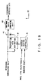
- Fig. 1 is a diagram describing a configuration of a conventional mobile communication system. In this description, an operation and a configuration relating to the Doppler shift are explained.
- a base transceiver station 500 comprises an antenna element 501, a separator (circulator) 502, an orthogonal demodulator 503, a Voltage Control Oscillator (VCO) 504, an uplink frequency synthesizer 505, a phase error detector 506, a synchronous detector 507, a demodulator 508, a encoder 509, a frame generator 510, a multiplexer 511, a downlink frequency synthesizer 512 and a orthogonal modulator 513.
- the base transceiver station 500 transmits data to a mobile station 600 in a prescribed unique wireless frequency using the VOC 504 and the downlink frequency synthesizer 512.
- the base transceiver station 500 detects a frequency error (a frequency offset) of received wave from the mobile station apparatus 600 using the phase error detector 506, and regenerates data compensating for the error.
- the mobile station apparatus 600 comprises an antennal element 601, a separator (circulator) 602, a orthogonal demodulator 603, a synchronous detector 604, a decoder 605, a handover controller 606, a phase error detector 607, an Automatic Frequency Control (AFC) unit 608, a VOC 609, a downlink frequency synthesizer 610, an encoder 611, a frame generator 612, an uplink frequency synthesizer 613, and an orthogonal modulator 614.
- the AFC unit 608 controls input voltage of the VOC 609 so that the frequency error (frequency offset) of the received wave from the base transceiver station apparatus 500 converges on zero.
- the mobile station apparatus 600 regenerates the received data and performs data transmission using a clock generated by the VOC 609. That is to say, the mobile station apparatus 600 uses the same clock for both regenerating data and transmitting data.
- a mobile station moves at a high speed on a train (particularly in a train such as a bullet train traveling at a high speed) or in a car, and a base transceiver station is located in a place where the radio path between the mobile station and the base transceiver station along a traveling route of the train or the car is under a line of sight (LOS) condition (a place where direct waves are transmitted and received between the mobile station and the base transceiver station) .
- LOS line of sight
- the Doppler shift equals to the frequency offset. Therefore, the mobile station has to perform AFC, which keeps up with wireless frequency including the Doppler shift.
- a mobile station approaches to a base transceiver station (BTS1)
- BTS1 base transceiver station
- the frequency of received wave on the antenna in the MS is higher by the amount of the Doppler shift. Therefore, as a result of AFC on the received wave, the frequency (downlink frequency) of a periodic wave used in the mobile station to receive a signal is controlled by "fc+fd".
- fc is a reference frequency of a carrier wave
- fd is a Doppler shift frequency.
- the same frequency as the downlink frequency obtained from the AFC is used as a frequency of a carrier wave for data transmission (uplink frequency) in the conventional mobile communication system. Therefore, the uplink frequency is also controlled at "fc+fd".
- the Doppler shift is also added to the uplink as well, and consequently, the frequency of the received wave in the base transceiver station (BTS1) becomes "fc+2fd". In other words, the frequency offset after the orthogonal modulation in the base transceiver station is twofold of the Doppler shift.
- a state in which the mobile station approaches to the base transceiver station changes into a state in which the mobile station recedes from the base transceiver station, and therefore, the polarity of the Doppler shift can be inverted within a short time period.
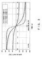
- the fluctuation in the Doppler shift fd can be expressed by the following equation where "v” represents a moving velocity of the mobile station, “c” is speed of light, "x” is a vertical distance from the base transceiver station (BTS1) to the traveling route of the mobile station, “t” is a elapsed time on the basis of the time when the mobile station passes in proximity of the base transceiver station (BTS1), and " ⁇ (t)” is an elevation angle when the base transceiver station (BTS1) is seen from the traveling direction of the mobile station.
- Fig. 3 is diagram showing fluctuation in the Doppler shift obtained by the above equation. As the moving velocity of the mobile station increases, the fluctuation range of the Doppler shift becomes wider. As the vertical distance from the base transceiver station to the moving route of the mobile station is smaller, the Doppler shift fluctuates within a shorter time period.
- the received frequency of the mobile station drastically fluctuates from "2G+600"Hz to "2G-600”Hz within a several seconds, and therefore, in order to minimize the frequency offset in the mobile station, the time constant of the AFC has to be set at high speed.
- the time constant of the AFC is set at high speed, the average time of the phase error detection is short with respect to noise and control steps of the frequency control is inexact. That is to say, increase in speed of the AFC and the accuracy of the frequency control are in a tradeoff relation.
- Patent Document 1 Japanese Patent Application Laid-open Publication No. 2002-101012
- Patent Document 1 suggests a technology to make the AFC band and tracking speed variable in accordance with the communication conditions.
- Patent Document 1 Japanese Patent Application Laid-open Publication No. 2002-101012
- the base transceiver station receives a frequency offset equivalent to twofold of the Doppler shift. For that reason, in the above case, the received frequency in the base transceiver station fluctuates by 2400Hz from "2G+1200"Hz to "2G-1200"Hz within a several seconds. Consequently, the requirement of increase in the speed in the frequency compensation in the base transceiver station (frequency compensation processing in synchronous detection based on the result of phase error detection) is further difficult than the conditions in the mobile station.
- the base transceiver station is designed to compensate for a frequency error of only 0.1ppm caused by the frequency stability of the mobile station.
- the frequency error that can be compensated is as much as ⁇ 200Hz. Therefore, in order to secure the reception quality under specific conditions that is an environment of high-speed moving in a path under LOS condition, the base transceiver station must be implemented with a frequency compensation circuit with the compensation range six times as wide as a usual design. Additionally, in order to realize the high-speed tracking, the frequency compensation accuracy has to be sacrificed.
- Fig. 2 assume a handover caused when a mobile station (MS) moves from a communication area of a base transceiver station (BTS1) to a communication area of another base transceiver station (BTS2).
- the assumed handover is a soft handover (SHO) in CDMA employed by the second generation and the third generation cellular phone systems.
- SHO soft handover
- CDMA the same frequency can be used in cells adjacent to each other. Therefore, the mobile station can switch reference cells, synthesizing signals from a plurality of base transceiver stations at the maximum ratio (i.e. soft handover).
- a conventional mobile station can perform the AFC on only one received frequency. For that reason, the mobile station generally performs the AFC on the received frequency of a reference cell alone. Then, as shown in Fig. 2, uplink/downlink frequency is controlled at "fc-fd" while the base transceiver station (BTS1) is the reference cell, and the uplink/downlink frequency is controlled at "fc+fd” after the reference cell is changed from the base transceiver station (BTS1) to the base transceiver station (BTS2).
- the mobile station synthesizes a pair of received waves with a frequency difference equivalent to twofold of the Doppler shift at the maximum ratio in the handover area.
- the reception quality is more deteriorated than the reception quality when the synthesize is not performed.
- Patent Document 2 Japanese Patent Application Laid-open Publication No. H10-200471
- Patent Document 3 Japanese Patent Application Laid-open Publication No. H11-355826
- the base transceiver station apparatus of the present invention transmits/receives radio wave to/from a mobile station, comprising: a detection unit for detecting a frequency offset of a received wave from the mobile station; and a frequency control unit for controlling transmission frequency of a carrier wave for transmitting a signal to the mobile station so as to cancel a Doppler shift, which occurs in a radio link connecting to the mobile station, based on the frequency offset detected by the detection unit.
- the Doppler shift caused by a mobile station moving at a high speed occurs both in the uplink and downlink, and therefore, the frequency offset, which is twofold of the Doppler shift, occurs in the conventional mobile communication system.
- the base transceiver station of the present invention By introducing the base transceiver station of the present invention, however, the Doppler shift in the downlink is cancelled.
- the frequency offset can be controlled to be equivalent to the Doppler shift.
- the mobile station apparatus of the present invention transmits/receives a radio wave to/from a base transceiver station, comprising: a reception unit for receiving frequency control information generated based on a frequency offset of a received wave in the base transceiver station; and a frequency control unit for controlling a transmission frequency of a carrier wave for transmitting a signal to the base transceiver station so as to cancel the frequency offset of the received wave in the base transceiver station based on the frequency control information.
- the Doppler shift in the uplink is cancelled, and therefore, the frequency offset in the base transceiver station apparatus becomes zero.
- the mobile station apparatus has a function for performing automatic frequency control to follow the Doppler shift, the frequency offset does not occur in the mobile station apparatus. In such a case, the frequency offsets can be controlled to zero in both the base transceiver station and the mobile station.
- the influence of the Doppler shift can be avoided or suppressed, it is possible to secure stable communication quality in a high-speed moving environment.
- the mobile communication system of the present invention having a mobile station and a plurality of base transceiver stations, comprising: a generation unit, provided in each of the base transceiver stations, for generating frequency control information based on a frequency offset of a received wave from the mobile station; and a frequency control unit, provided in the mobile station, for controlling a transmission frequency for transmitting a signal to a base transceiver station based on the frequency control information generated in at least one of the plurality of base transceiver stations.
- the frequency control unit may control the transmission frequency based on frequency control information form a base transceiver station with the best reception quality.
- the frequency control unit may combines frequency control information from each of base transceiver stations using reception quality of a signal from each of the base transceiver stations as weights, and controls the transmission frequency based on the weighted combination result.
- a transmission frequency is controlled so as to cancel the Doppler shift caused in a radio link or to cancel the frequency offset in a receiving station, the reception quality in both a transmitting station and a receiving station can be improved in a high-speed moving environment. By so doing, it is possible to acquire stable communication quality in both uplink and downlink.
- uplink a path for transmitting a signal from a mobile station to a base transceiver station
- downlink a path for transmitting a signal from a base transceiver station to a mobile station
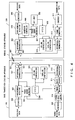
- Fig. 4 is a diagram showing a configuration of a mobile communication system of the first embodiment.
- a base transceiver station apparatus 100 comprises a phase rotator 1 in addition to the antenna element 501, the separator (circulator) 502, the orthogonal demodulator 503, the Voltage Control Oscillator (VCO) 504, the uplink frequency synthesizer 505, the phase error detector 506, the synchronous detector 507, the decoder 508, the encoder 509, the frame generator 510, the multiplexer 511, the downlink frequency synthesizer 512, and the orthogonal modulator 513.
- VCO Voltage Control Oscillator
- the received signal input via the antenna element 501 is down-converted into a base band signal in the orthogonal demodulator 503 after being separated from the transmission signal by the circulator 502.
- the VCO 504 generates a reference clock
- the uplink frequency synthesizer 505 generates a periodic wave with a predetermined frequency unique to the system (a sinusoidal wave, for example) from the reference clock under PLL control.
- the orthogonal demodulator 503 obtains the base band signal by multiplying the periodic wave on the received signal.
- the phase error detector 506 detects the frequency offset (i.e. the error between the reference frequency in the base transceiver station apparatus 100 and the frequency of the received wave from the mobile station apparatus 200) by taking time correlation of a given signal (a pilot signal) multiplexed on the base band signal in advance.
- the frequency offset can be detected for each mobile station.
- the synchronous detector 507 calculates an estimated value of a path fluctuation by in-phase addition of the pilot signal, while compensating for the above frequency offset.
- a complex conjugate which is a result of the addition of phase rotation equivalent to the frequency offset to the estimated value, is calculated, then the above base band signal is multiplied by the complex conjugate.
- the decoder 508 performs decoding processing such as de-interleaving and error correction decoding on the received symbol after the synchronous detection, and the regenerated data series is output.
- the encoder 509 performs encoding processing such as error correction encoding and interleaving to transmission data series for each mobile station.
- the frame generator 510 performs time-multiplexing of the encoded data in a prescribed frame format.
- the phase rotator 1 rotates the phase of the base band signal output from the frame generator 510 in accordance with the instruction from the phase error detector 506 for each mobile station of transmission destination.
- the multiplexer 511 sums the output signals of the phase rotator 1.
- the base band signal after multiplexing is up-converted into RF band in the orthogonal modulator 513, and sent out via the antenna element 501 while being separated from the received signal by the circulator 502.
- the carrier wave used for the up-conversion is generated by the VCO 504 and the downlink frequency synthesizer 512.
- the radio frequencies of the uplink and downlink are the same, and in a FDD (Frequency Division Duplex) system, the radio frequencies of uplink and downlink are separated from each other by a prescribed band.
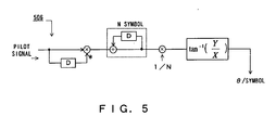
- Fig. 5 is a diagram showing an example of the phase error detector 506.
- a pilot signal is input in the phase error detector 506.
- the correlation between the adjacent symbols i.e. time correlation
- an average of correlation value for N symbols is calculated.
- the phase error ⁇ per one symbol can be obtained.
- Fig. 6A to Fig. 6C are diagrams explaining the operation of the phase rotator 1.
- data is transmitted by BPSK modulation.
- "0" or " ⁇ " is assigned to each symbol (1 or 0) as shown in Fig. 6A.
- the modulated data is transmitted by a carrier wave with frequency f 0 .
- the phase rotator 1 rotates the phase of the transmission symbol in the base band region in accordance with the instruction from the phase error detector 506. As a result, the transmission frequency of the carrier wave is controlled in accordance with the frequency offset.
- the phase error detector 506 detects the frequency offset of received waves from each mobile station, and the phase rotator 1 can control the transmission frequency of the carrier wave for each mobile station.
- a mobile station apparatus 200 is basically the same as the mobile station 600 shown in Fig. 1, comprising an antenna element 601, a separator (circulator) 602, an orthogonal demodulator 603, a synchronous detector 604, a decoder 605, a handover controller 606, a phase error detector 607, an Automatic Frequency Control (AFC) unit 608, a VCO 609, a downlink frequency synthesizer 610, an encoder 611, a frame generator 612, an uplink frequency synthesizer 613, and an orthogonal modulator 614.
- the operations of the devices other than the AFC unit 608, the synchronous detector 604, and the handover controller 606 are basically the same as those of the base transceiver station 100, and therefore the explanation of those devices is omitted.
- the AFC unit 608 controls the input voltage of the VCO 609 so that the frequency offset detected by the phase error detector 607 converges on zero.
- the training operation on the frequency is performed so that the downlink frequency of the mobile station 200 (the frequency of a periodic wave given from the downlink frequency synthesizer 610 to the orthogonal modulator 603) matches to the frequency of the received wave from the base transceiver station 100.
- the frequency offset of the base band signal is zero. Therefore, the synchronous detector 604 compensates for only phase rotation caused in a propagation path based on the estimated value of the propagation path.
- the reference clock that a VCO (the VCO 609 in the embodiments) generates is provided to both uplink and downlink frequency synthesizers (610 and 613). In other words, the AFC is performed on the uplink and downlink frequencies at the same time.
- the handover controller 606 measures the reception quality for each base transceiver station (reception power, reception SIR etc.) using the orthogonal demodulated data of the control signal transmitted from the base transceiver station connected to the mobile station and its adjacent base transceiver stations. Following the movement of the mobile station, a switch (handover) of a base transceiver station (a reference cell), which has the best reception quality, is constantly performed as needed. During handover, signals from a plurality of base transceiver stations are simultaneously received. At that time, the phase error detector 607, by being informed of the ID of the reference cell from the handover controller 606, detects the frequency offset to the received wave of the reference cell. Therefore, during the handover, the AFC is performed to the received wave from a base transceiver station of the reference cell.
- the phase rotator 1 in the base transceiver station 100 performs phase rotation of the downlink frequency so that the Doppler shift generated in the downlink from the base transceiver station apparatus 100 to the mobile station apparatus 200 is canceled, based on the frequency offset detected by the phase error detector 506.
- the phase rotation is performed to each symbol in the downlink by performing a complex multiplication of the opposite phase of the phase equivalent to the detected frequency offset. For example, when the phase error corresponding to the frequency offset detected by the phase error detector 506 is " ⁇ 1", the phase of each symbol of downlink is rotated by "- ⁇ 1".
- phase rotation is performed for each transmission destination (i. e. mobile station). For that reason, processing for canceling the frequency offset is performed on each of dedicated channels.
- downlink frequency control in the base transceiver station 100 is started after the start of communication in dedicated channels caused by the call request from the mobile station.
- Fig. 7 is a diagram explaining the frequency control in the mobile communication system of the first embodiment.
- a mobile station moves along a path 301 at velocity v, and passes near a base transceiver station (BTS1) and a base transceiver station (BTS2). It is assumed that the vertical distance from the base transceiver station (BTS1) and the base transceiver station (BTS2) to the path 301 is "x", respectively.
- the system-specific carrier wave frequency is f 0 .
- each base transceiver station detects the frequency offset caused by the Doppler shift, and controls the downlink transmission frequency based on the frequency offset.
- the mobile station does not have to comprise any special function for the frequency control of the present invention.
- each base transceiver station periodically broadcasts a control signal using a common channel.
- the mobile station performs AFC to the received wave in the common channel from the base transceiver station (BTS1) before call request to use of a dedicated channel.
- the frequency of the received wave detected by the mobile station is "fc+fd".
- "fd” is a frequency caused by the Doppler shift.
- the transmission frequency for returning a response signal from the mobile station to the base transceiver station (BTS1) is also "fc+fd".
- the frequency of the received wave detected by the base transceiver station (BTS1) is "fc+2fd”.
- the Doppler shift frequency is added on the downlink, and therefore, the frequency of the received wave in the mobile station becomes "fc". In other words, the Doppler shift fd is cancelled.
- the mobile station after starting the communication in a dedicated channel, performs the AFC over the received wave of the dedicated channel. Therefore, the uplink frequency and the downlink frequency in the mobile station converge on "fc" within the time period equivalent to the time constant of the AFC. As a result, the frequency offset, which the mobile station receives, becomes zero, and an ideal reception environment is realized.
- the Doppler shift for one way (i.e. fd) remains in the received wave of the base transceiver station; however, compared to the case that the frequency control of the first embodiment is not performed, the frequency offset is suppressed by half.
- the base transceiver station continues the frequency control for adding "- ⁇ f 0 /2" to the carrier wave frequency fc for the time period from the start of the frequency control to elapse of " ⁇ ".
- the frequency control is switched to a dynamic frequency control for adding "- ⁇ f(t)” to the carrier wave frequency fc.
- the "- ⁇ f(t)” is a frequency corresponding to the phase error periodically detected by the phase error detector 506.
- the base transceiver station adds the phase rotation equivalent to "- ⁇ f(t)", which dynamically changes in accordance with the movement of the mobile station, to the transmission symbol. Therefore, as shown in Fig.
- the transmission frequency of the base transceiver station can keep up with the change, and consequently, it is possible to maintain the frequency offset in the mobile station at zero.
- the base transceiver station (BTS1) and the base transceiver station (BTS2) are in the soft handover state. Then, the base transceiver station (BTS2) starts the frequency control using "- ⁇ f (t)". At that time, the frequency control is performed by the base transceiver station (BTS1); therefore, the transmission frequency of the mobile station is maintained at "fc". For that reason, the frequency offset in the base transceiver station (BTS2) is equivalent to the Doppler shift (i.e. fd) caused by propagation in one way.
- the base transceiver station (BTS2) adds the phase rotation that cancels the Doppler shift (fd) to the downlink base band signal. Therefore, in the mobile station, the frequency offset is controlled to zero in the received wave from the base transceiver station (BTS2), like the received wave from the base transceiver station (BTS1).
- the frequency control of the downlink signal is performed so that the frequency offset of the received wave from any of the base transceiver stations becomes zero in the mobile station. Therefore, the mobile station, in the soft handover, a plurality of received waves, in each of which the Doppler shift is substantially zero, can be synthesized, and therefore, the deterioration of the reception quality can be prevented.
- the reception quality was deteriorated because a received wave with frequency shifted to positive side and a received wave with frequency shifted to negative side are synthesized in the handover section.
- each of the base transceiver stations concerning the handover controls the transmission frequency so as to cancel the Doppler shift for the target mobile station, the mobile station does not synthesize the received waves with different Doppler shift polarities as in the conventional example, and therefore, deterioration of the reception quality can be avoided.
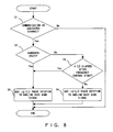
- Fig. 8 is a flowchart showing an operation of the phase rotator 1. Processing in the flowchart is periodically repeatedly, for example.
- step S1 whether or not the communication is performed in the dedicated channel is examined. If not in the dedicated channel, the processing is terminated without the frequency control.
- step S2 whether it is in the handover state or not is examined. If not in the handover state, in step S3, whether or not " ⁇ " has elapsed from the start of the frequency control is examined.
- the frequency control is started upon the call request from the mobile station, for example. " ⁇ ” is, as explained above, equivalent to the convergence time of the AFC in the mobile station.
- the phase rotation equivalent to the "- ⁇ f 0 /2" is added to the downlink signal in the base band region in step S4.
- step S5 is performed.
- the frequency offset in the base transceiver station becomes half compared with that of the conventional system.
- a plurality of received waves without frequency offset can be synthesized in handover section. Therefore, the reception quality can be improved both in the base transceiver station and the mobile station (especially in the mobile station).
- the base transceiver station apparatus 100 may add a phase rotation equivalent to twofold of the Doppler shift to the transmission symbol.
- the transmission frequency of the base transceiver station becomes "fc-2fd"
- the reception frequency of the mobile station becomes "fc-fd"
- the transmission frequency of the mobile station becomes "fc-fd” under the AFC. Consequently, the reception frequency of the base transceiver station becomes "fc”.
- phase rotation i.e. frequency control
- frequency offset equivalent to the Doppler shift remains in the mobile station; however, the frequency offset can be zero in the base transceiver.
- Fig. 9 is a diagram showing a configuration of the mobile communication system of the second embodiment.
- a frequency control (FC) command generator 11 is provided in a base transceiver station apparatus 110 shown in Fig. 9.
- a frame generator 12 comprises a function for writing in a frequency control command generated by the FC command generator 11 in a prescribed region, in addition to functions comprised in the frame generator 510 shown in Fig. 1.
- a mobile station apparatus 210 in addition to the conventional configuration shown in Fig. 1, comprises a downlink VCO 21, an uplink VCO 22, and a frequency controller 23 for controlling the uplink VCO 22 in accordance with the frequency command transmitted from the base transceiver station. During reception of the frequency command, the frequency of the uplink VCO 22 is controlled independently of the downlink VCO21.
- the downlink VCO 21 is basically the same as the VCO 609 shown in Fig. 4.
- FC command the frequency control command
- the frequency control command generator 11 comprised in the base transceiver station apparatus 110 generates an FC command to be transmitted to the corresponding mobile station based on the frequency offset of each mobile station detected by the phase error detector 506.
- the FC command is a control signal for canceling the frequency offset in the received wave in the base transceiver station, and is generated as described below.
- the FC command is generated as below.
- the frequency control step "a" is a fixed value determined in advance.
- a multi-valued signal comprising a signal for instructing increase/decrease of the frequency and for instructing control step of the frequency
- the amount of ⁇ f detected by the phase error detector 506 is determined using prepared thresholds, and a FC command presenting the determination result is generated.
- a multi-valued signal comprising a quantized value of the frequency offset detected by the phase error detector 506 and its sign
- the convergence time in the frequency control in the mobile station is the longest in the form 1, and is the shortest in the form 3.
- overhead due to the FC command in the downlink is the smallest in the form 1, and is the largest in the form 3.
- the convergence time and the overhead are in a trade-off relation to each other. Therefore, it is desirable that the selection of the FC command form is made properly in accordance with the upper limit of the moving speed predicted by the system and the carrier frequency that propagates the signal.
- the FC command generated in the above manner is time-multiplexed to a prescribed region in a slot of a format A shown in Fig. 10 by the frame generator 12, and then, it is transmitted to the corresponding mobile station.
- the slot is the smallest unit of the transmission format, and the slot time is equivalent to a repetition period of the frequency control.
- N PILOT is number of bits of the pilot signal.
- N FC is number of bits of the FC command.
- N DATA is number of bits of the encoded data. This format is the same in the third through the seventh embodiments explained later.
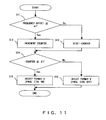
- Fig.11 is a flowchart showing an operation of the frame generator 12. The processing is repeatedly performed in a prescribed time period.
- step S11 whether or not the absolute value of the detected frequency offset is equal to or larger than the threshold ⁇ is examined. If the absolute value of the detected frequency offset is equal to or larger than the threshold ⁇ , a protection stage counter is incremented in step S12. If not, the protection stage counter is reset in step S13.
- step S14 whether or not the count value of the protection stage counter is equal to or larger than the threshold ⁇ is examined. If the count value of the protection stage counter is equal to or larger than the threshold ⁇ , in step S15, the format A shown in Fig. 10 is selected. If not, in step S16, a format B shown in Fig. 10 is selected.
- the processing in this flowchart may be performed in the third through the seventh embodiments explained later.
- the format A including the FC command is selected and the frequency control becomes valid.
- the format B without the FC command is selected, and the frequency control becomes invalid.
- the type information indicating the selected format is multiplexed to the control signal and is notified to the mobile station. By so doing, the mobile station can recognize whether the frequency control is valid or invalid.
- the same function can be realized using the format A shown in Fig. 10 alone rather than using two types of formats as in above.
- the mobile station can recognize whether the frequency control is valid or invalid by monitoring the reception level of the FC command, and therefore, the control information for format identification is not needed.
- the environment where the frequency control is required can be specified to a certain extent in a setting condition of the base transceiver station (such as alongside of a highway or a railway, and presence/absence of an obstacle). Therefore, instead of the dynamically determining whether the frequency control is needed, the format selection or valid/invalid control using the DTX transmission can be performed according to the setting condition of the base transceiver station. Specifically, for example, a method in which valid/invalid of the frequency control is set as a control parameter unique to the base transceiver station in advance is possible.
- the mobile station apparatus 210 obtains the above FC command by decoding the received signal in the decoder 605.
- the FC command is transmitted to the frequency controller 23.
- the frequency controller 23 calculates a frequency to be generated by adding the frequency instructed by the FC command to the current uplink frequency. For example, when the current uplink frequency is "fcc (Hz)", if the FC command received from the base transceiver station indicates "+a(Hz)", “fcc+a(Hz)" is obtained. In the same manner, when the FC command indicates "-a (Hz)", “fcc-a (Hz)” is obtained.
- the frequency controller 23 generates control voltage corresponding to the calculated frequency and inputs it to the uplink VCO 22.
- a method to control the downlink frequency is the same as the conventional ones, and the FC command is used only for the control of the uplink frequency.
- control voltage from the AFC unit 608 is also input to the frequency controller 23.
- the frequency controller 23 controls the uplink VCO 22 using the control voltage from the AFC unit 608. In such a case, like the conventional art, the uplink frequency and the downlink frequency become equal to each other.
- the control voltage to be input to the uplink VCO 22 is generated by either one of the following methods. Assume that the handover controller 606 monitors the quality of the received signal from each surrounding base transceiver station.
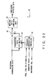
- Fig. 12 is a diagram explaining a sequence of the frequency control. The sequence is performed in the third through the seventh embodiment explained later.
- downlink data of slot #N is transmitted from the base transceiver station to the mobile station.
- the phase error detector 506 in the base transceiver station calculates the frequency offset of the received wave by the time correlation of the pilot signal included in the uplink data of slot #N.
- the FC command generator 11 generates the FC command by either one of the above methods based on the calculated frequency offset.
- processing time T d1 occurs from the reception of the pilot signal to generation of the FC command.
- the generated FC command is inserted into a prescribed position of the downlink data of slot #N+1 by the frame generator 12, and is transmitted to the mobile station.
- the decoder 605 decodes the FC command from the received slot. It takes time T d2 for this decoding processing.
- the decoded FC command is converted into control voltage for controlling an oscillation frequency of the uplink VCO 22 in the frequency controller 23. Therefore, the mobile station transmits slot #N+1 with a frequency controlled in accordance with the FC command. Subsequently, by repeating the above frequency control in a slot period, in the mobile station, it is possible to control the uplink frequency independently of the downlink frequency.
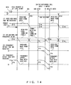
- Fig. 13 and Fig. 14 are diagrams explaining the frequency control in the mobile communication system of the second embodiment.
- the controls shown in Fig. 13 and Fig. 14 are different from each other in the handover section.
- a relative positions of a mobile station (MS) and base transceiver stations (BTS1 and BTS2) and a propagation environment between the mobile station and the base transceiver stations are the same as explained with reference to Fig. 7.
- the mobile station performs the AFC on the received wave via the common channel from the base transceiver station (BTS1) prior to the start of the call request of dedicated channel.
- the frequency of the received wave of the base transceiver station (BTS1) is "fc+2fd".
- the frequency offset ⁇ f 0 detected by the base transceiver station (BTS1) is equivalent to twofold of the Doppler shift.
- the base transceiver station (BTS1) Upon detecting the call request from the mobile station, the base transceiver station (BTS1) starts control of the uplink frequency using the FC command. At that time, the FC command instructs the control of the transmission frequency to the mobile station so that the frequency offset at the base transceiver station (BTS1) becomes zero.
- the transmission frequency of the mobile station converges on "fc-fd".
- the frequency of the received wave of the base transceiver station apparatus (BTS1) becomes "fc”.
- the frequency offset of the base transceiver station (BTS1) becomes zero.
- the frequency control is not performed on the downlink. Therefore, the frequency of the received wave of the mobile station becomes "fc+fd". In other words, the frequency offset to be compensated for in the mobile station is "fd" as in the conventional art shown in Fig. 2.
- both base transceiver stations are in the soft handover state.
- the controls of the handover state are different from one another in Fig. 13 and Fig. 14.
- the mobile station performs the AFC based on only the FC command from the base transceiver station (BTS1). Therefore, the transmission frequency of the mobile station is maintained at "fc+fd", and the frequency offset in the base transceiver station (BTS1) remains zero. However, during this period, the frequency offset in the base transceiver station (BTS2) is "2fd". At that time, the quality of the received signal from the base transceiver station (BTS1) is high, however the quality of the received signal from the base transceiver station (BTS2) is low. Consequently, in the present embodiment, the mobile station may regenerate data by using only a signal from the base transceiver station (BTS1) rather than by combining signals from the base transceiver station (BTS1) and the base transceiver station (BTS2).
- the mobile station When the reference cell is switched from the base transceiver station (BTS1) to the base transceiver station (BTS2), the mobile station performs the AFC based on the FC command from the base transceiver station (BTS2) . Therefore the transmission frequency of the mobile station shifts from "fc+fd" to "fc-fd” at a speed according to the time constant of the feedback control. As a result, the frequency offset in the base transceiver station (BTS2) becomes zero; however, the frequency offset in the base transceiver station (BTS1) becomes "2fd".
- the FC commands from the base transceiver station (BTS1) and the base transceiver station (BTS2) are combined using the reception quality as weight. Then, the transmission frequency of the mobile station slowly shifts from "fc+fd" to "fc-fd".
- the frequency offset in the base transceiver station apparatus (BTS2) which approaches to the mobile station can be kept smaller than "2fd". Consequently, the frequency offset is favorably distributed to the base transceiver stations which relates to the handover.
- Fig. 15 is a diagram showing a configuration of the mobile communication system of the third embodiment.
- the base transceiver station apparatus 120 and the mobile station apparatus 220 shown in Fig. 15 are basically the same as the base transceiver station apparatus 110 and the mobile station apparatus 210 of the second embodiment. However, in the base transceiver station apparatus 120 of the third embodiment, it is not necessary to transmit the detection result by the phase error detector 506 to the frame generator 12.
- the downlink VCO 21 for generating the periodic wave for down-converting the downlink signal is controlled by the control voltage generated by the frequency controller 23.
- the FC command generator 11 generates the FC command in which the frequency control ON/OFF bit (for example 0: OFF and 1:ON) is added to the highest-order bit (or Most Significant Bit) in a command generated in the second embodiment.
- the command generated in the second embodiment can be any one of the above three types of commands.
- the frequency control ON/OFF bit is, like the valid/invalid determination of the frequency control in the second embodiment, generated based on the comparison between the frequency offset detected by the phase error detector 506 and the threshold, or the setting conditions of the base transceiver station.
- the frame generator 12 inserts the above FC command into the format A shown in Fig. 10 regardless of the validity/invalidity of the frequency control, and transmits with a prescribed power.
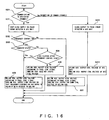
- the frequency controller 23 in the mobile station apparatus 220 upon receiving the FC command, generates the control voltage to be provided to the downlink VCO 21 and the uplink VCO 22 in accordance with the flowchart shown in Fig. 16.
- step S21 whether or not the communication is performed in the dedicated channel is examined. If the communication is performed in the dedicated channel, the processing proceeds to step S31, and otherwise, the processing proceeds to step S22. Assume that the mobile station receives the control signal from the base transceiver station via the common channel when the communication is not performed in dedicated channel.
- the mobile station while receiving the control signal from the base transceiver station via the common channel, basically does not receive the FC command. Therefore, in such a case, the frequency controller 23 provides the control voltage generated by the AFC unit 608 to the downlink VCO 21 and the uplink VCO 22.
- the frequency control function by the AFC can be substituted by a control using the FC command, and therefore, the clock supplies to the phase error detector 607 and the AFC unit 608 are stopped. By so doing, it is possible to reduce the power consumption of the redundant block.
- the frequency control ON/Off is identified by the highest-order bit of the received FC command.
- the frequency control is performed, the uplink frequency and the downlink frequency different from each other are generated. Meanwhile, when the frequency control is not performed, the uplink frequency and the downlink frequency become the same.
- the control voltage for the uplink VCO 22 is generated.
- the generation of the control voltage is the same as in the second embodiment. That is to say, when the mobile station approaches to the base transceiver station, the uplink VCO 22 is controlled so that the transmission frequency becomes "fc-fd". When the mobile station recedes from the base transceiver station, the uplink VCO 22 is controlled so that the transmission frequency becomes "fc+fd". AT that time, the reception frequency can be obtained by adding the Doppler shift frequency fd with opposite polarity from the transmission frequency to the reference frequency fc.
- the downlink VCO 21 is controlled so that the reception frequency becomes "fc+fd".
- the downlink VCO 21 is controlled so that the reception frequency becomes "fc-fd".
- the uplink frequency and the down link frequency shown in Fig. 13 and Fig. 14 are obtained, and therefore, in a high-speed moving environment under the line of sight condition, the frequency offset in both base transceiver station and the mobile station become zero.
- the AFC is not necessary, and thus, both high-speed and wide-band frequency control can be realized to the downlink frequency in addition to the uplink frequency.
- a complex variable control circuit described in the Patent Document 1 is not required.
- the downlink frequency control is not performed. Therefore, during the time period in which a prescribed time ⁇ elapses from the start of the frequency control, the frequency controller 23 updates only the control voltage of the uplink VCO 22 in accordance with the FC command, and does not update the control voltage of the downlink VCO 22.
- the frequency controller 23 in accordance with the frequency control information in the FC command, outputs the same control voltage value to both of the downlink VCO 21 and the uplink VCO 22. In such a case, the same operation as the AFC in the conventional system shown in Fig. 1 can be realized.
- Fig. 17 is a diagram showing a configuration of the mobile communication system of the fourth embodiment.
- the base transceiver station apparatus 130 and the mobile station apparatus 230 shown in Fig. 17 are basically the same as the base transceiver station apparatus 110 and the mobile station apparatus 210 in the second embodiment.
- the VCO 609 controlled by the AFC unit 608 is comprised in the mobile station apparatus 230 of the fourth embodiment.
- a phase rotator 31 for rotating the phase of the transmission symbol in a base band region in accordance with the instruction from the frequency controller 23 is also comprised.
- the frequency controller 23 converts a frequency updated by the FC command into the phase rotation ⁇ , and provides the phase rotation ⁇ to the phase rotator 31.
- the phase rotator 31 performs complex-multiplication of "exp(j ⁇ )" to the uplink signal in the base band region. By so doing, the phase of the uplink signal in the base band region rotates by " ⁇ ".
- control similar to the second embodiment can be realized without comprising VCOs to each of the uplink and downlink.
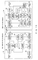
- Fig. 18 is a diagram showing a configuration of the mobile communication system of the fifth embodiment.
- a base transceiver station apparatus 140 and a mobile station apparatus 240 are basically the same as the base transceiver station apparatus 110 and the mobile station apparatus 210 in the second embodiment.
- a synchronous detector 41 comprised instead of the synchronous detector 604 performs detection operation regarding to the instruction from the handover controller 606 and the frequency controller 23.
- Fig. 19 is a diagram showing a configuration of the synchronous detector of the fifth embodiment.
- the synchronous detector 41 comprises a propagation path estimation unit 42, a complex-multiplier 43, a maximum ratio combining unit 44, and an average section controller 45.
- the propagation path estimation unit 42 calculates a propagation path estimated value (an estimated value of the propagation path change) by taking in-phase adding and averaging of the pilot signal included in the orthogonal demodulated data of the downlink.
- the propagation path estimation unit 42 also, in the soft handover, calculates propagation path estimated value of each of the propagation paths between the mobile station and a plurality of base transceiver stations relating to the handover.
- the complex-multiplier 43 multiplies orthogonal demodulated data by a complex conjugate of corresponding propagation path estimated value. By so doing, synchronous detection is performed for each received signal.
- the maximum ratio combining unit 44 performs the maximum ratio combination for a plurality of synchronous detection results, and outputs ultimate synchronous detection data.
- Fig. 20 is an example of the propagation path estimation unit 42 used in the fifth embodiment.
- the pilot signals stored in the head of each slot is periodically input.
- the propagation path estimation unit 42 calculates an average of consecutive N pilot signals. The result of this averaging is the propagation path estimation value (an estimated value of the phase fluctuation in the propagation path).
- the propagation path estimation unit 42 performs propagation path estimation in response to the instruction from the average section controller 45.
- the average section controller 45 gives the propagation path estimation unit 42 an instruction for reducing the additive averaging time compared with that of the normal condition.
- the propagation path estimation unit 42 which received this instruction, reduces the number of the pilot signals to be averaged. By so doing, the time constant of the propagation path estimation becomes short, and the response speed of the phase compensation operation can be enhanced.
- the handover controller 606 determines whether the frequency control is valid or invalid.
- the downlink data is received from both of the base transceiver station (BTS1) receding from the mobile station and the base transceiver station (BTS2) approaching to the mobile station.
- the reception frequency of a pair of the downlink signals received from the two base transceiver stations (BTS1 and BTS2) are different by "2fd". Therefore, for example, when the frequency control based on the above second embodiment is performed, the maximum ratio combination is performed on the pair of downlink received signals with frequencies deviated by "2fd", and therefore, the reception quality during the handover period may be deteriorated.
- the time constant of the propagation path estimation is controlled to be short, the phase compensation which can keep up with the phase rotation caused by the frequency offset is realized.
- the phase compensation which can keep up with the phase rotation caused by the frequency offset is realized.
- the configuration of the mobile communication system of the sixth embodiment is basically the same as that of the fifth embodiment shown in Fig. 18. However, in the fifth and the sixth embodiments, the operations of the synchronous detector 41 are different from each other.
- Fig. 21 is a diagram showing the configuration of the synchronous detector of the sixth embodiment.
- the configuration of the synchronous detector of the sixth embodiment is basically the same as that of the fifth embodiment.
- the synchronous detector of the sixth embodiment comprises a base transceiver station selector 46 instead of the average section controller 45 of the fifth embodiment.
- the base transceiver station selector 46 selects only the base transceiver station provided in the reference cell. On the other hand, during the period when the above conditions are not satisfied, the base transceiver station selector 46 selects all (or a part of) base transceiver stations relating to the handover.
- the reference cell is detected by the handover controller 606.
- the propagation path estimation unit 42 performs the propagation path estimation and the maximum ratio combination only on the signal(s) received from the base transceiver station(s) selected by the base transceiver station selector 46.
- the synchronous detection is performed by using only the signal received from the base transceiver station in the reference cell.
- the maximum ratio combination is performed on the downlink signals with frequency difference "2fd". For that reason, under such environment, it is possible that the reception quality is further deteriorated by performing the maximum ratio combination.
- the sixth embodiment in the soft handover under the high-speed moving environment, the synchronous detection is performed using only the signal from the base transceiver station in the reference cell with the highest reception quality, and thus, it is possible to avoid the deterioration of the reception quality caused by the maximum ratio combination.
- the configuration of the mobile communication system of the seventh embodiment is basically the same as that of the fifth embodiment shown in Fig. 18. However, the operations of the synchronous detector 41 are different between the fifth and the seventh embodiments.
- Fig. 22 is a diagram showing the configuration of the synchronous detector of the seventh embodiment.
- the synchronous detector 41 of the seventh embodiment comprises a frequency compensation controller 52 and a propagation path estimation unit 53 instead of the average section controller 45 and the propagation path estimation unit 42.
- the frequency compensation controller 52 performs the frequency offset compensation when the mobile station is in the handover state and the frequency control is valid in one or a plurality of the base transceiver stations relating to the handover, and does not perform the frequency offset compensation when the above conditions are not met.
- the frequency compensation controller 52 When the frequency offset compensation is valid, the frequency compensation controller 52 notifies the propagation path estimation unit 53 of the frequency offset to be compensated for in the received wave from each base transceiver station relating to the handover.
- the "frequency offset to be compensated for" is calculated by the frequency controller 23 based on the FC command transmitted from each base transceiver station.
- the propagation path estimation unit 53 estimated the propagation path to each of the base transceiver stations, while compensating for the frequency offset notified from the frequency compensation controller 52.
- Fig. 23 is an example of the propagation path estimation unit used in the seventh embodiment.
- the propagation path estimation unit 53 like the propagation path estimation unit 42 shown in Fig. 20, calculates in-phase additive averaging of the pilot signals.
- the input signal of the additive averaging circuit is multiplied by "exp(-jn ⁇ )"
- the output signal from the additive averaging circuit is multiplied by "exp (jm ⁇ )”.
- ⁇ is a phase rotation per one symbol
- n is a symbol position of added pilot signal when the head symbol of the target slot is zero (n is an integer, which the future direction from the head of the target slot is a positive value)
- the propagation path estimation is performed while compensating for the frequency offset, the estimation accuracy by the in-phase addition is improved.
- the synchronous detection is performed by using the result of adding the phase rotation for the amount of the frequency offset to the calculated propagation path estimation value, and therefore, it is possible to compensate for the phase fluctuation in the propagation path and the phase fluctuation caused by the frequency offset at the same time.
- the synchronous detection is performed while compensating for the frequency offset remaining in each base transceiver station, and consequently, reception quality deterioration in the maximum ratio combination can be completely avoided.
- synchronous detection operation in the mobile station is changed in the handover, a favorable demodulation processing can be performed even if the polarity of the Doppler shift of the received wave from one base transceiver station is different from the polarity of the Doppler shift of the received wave from another base transceiver station. Consequently, it is possible to improve the reception quality in the handover operation.
- All of the fifth through the seventh embodiments improve the reception quality in soft handover under high-speed moving environment.
- the effect of the reception quality improvement is the most significant in the seventh embodiment, and the fifth embodiment stands the next, followed by the sixth embodiment.
- the processing of the synchronous detection becomes complicated. Therefore, which embodiments should be introduced should be determined according to the required reception quality level and the impact (the cost etc.) in implementation.
Landscapes
- Engineering & Computer Science (AREA)
- Computer Networks & Wireless Communication (AREA)
- Signal Processing (AREA)
- Power Engineering (AREA)
- Mobile Radio Communication Systems (AREA)
- Circuits Of Receivers In General (AREA)
- Digital Transmission Methods That Use Modulated Carrier Waves (AREA)
- Transceivers (AREA)
Applications Claiming Priority (1)
| Application Number | Priority Date | Filing Date | Title |
|---|---|---|---|
| JP2005268556A JP4699843B2 (ja) | 2005-09-15 | 2005-09-15 | 移動通信システム、並びに移動通信システムにおいて使用される基地局装置および移動局装置 |
Publications (3)
| Publication Number | Publication Date |
|---|---|
| EP1764968A2 true EP1764968A2 (de) | 2007-03-21 |
| EP1764968A3 EP1764968A3 (de) | 2012-06-06 |
| EP1764968B1 EP1764968B1 (de) | 2014-09-10 |
Family
ID=37553283
Family Applications (1)
| Application Number | Title | Priority Date | Filing Date |
|---|---|---|---|
| EP05257681.6A Expired - Lifetime EP1764968B1 (de) | 2005-09-15 | 2005-12-14 | Sende-/Empfangsschaltung mit Vorkompensation von Doppler Verschiebungen |
Country Status (5)
| Country | Link |
|---|---|
| US (1) | US8179926B2 (de) |
| EP (1) | EP1764968B1 (de) |
| JP (1) | JP4699843B2 (de) |
| KR (1) | KR100858303B1 (de) |
| CN (1) | CN1933365B (de) |
Cited By (4)
| Publication number | Priority date | Publication date | Assignee | Title |
|---|---|---|---|---|
| WO2008077679A1 (en) * | 2006-12-22 | 2008-07-03 | Telefonaktiebolaget Lm Ericsson (Publ) | Method of and apparatus for adaptive frequency error estimation |
| EP2133708A3 (de) * | 2008-06-09 | 2010-09-15 | Fujitsu Ltd. | Funkkommunikationsgerät und Frequenzversatzberechnungsverfahren |
| EP2192814A4 (de) * | 2007-09-11 | 2014-03-19 | Fujitsu Ltd | Drahtlose basisstation und verfahren zu ihrer steuerung |
| EP2154802A4 (de) * | 2007-05-29 | 2014-03-26 | Mitsubishi Electric Corp | Kalibrationsverfahren, kommunikationssystem, frequenzsteuerverfahren und kommunikationseinrichtung |
Families Citing this family (40)
| Publication number | Priority date | Publication date | Assignee | Title |
|---|---|---|---|---|
| JP4679644B2 (ja) * | 2007-02-05 | 2011-04-27 | 富士通株式会社 | 無線端末装置 |
| US20090036144A1 (en) * | 2007-07-31 | 2009-02-05 | Wong Wendy C | Techniques for mobility induced error correction |
| WO2009031183A1 (ja) * | 2007-09-05 | 2009-03-12 | Fujitsu Limited | 基地局装置、移動局装置、移動通信システム、及び周波数制御方法 |
| CN101911511B (zh) | 2007-12-26 | 2016-05-11 | 日本电气株式会社 | 相位噪声校正电路、发送器、接收器、无线电设备、无线电通信系统以及相位噪声校正方法 |
| KR101459014B1 (ko) | 2008-02-04 | 2014-11-07 | 삼성전자주식회사 | 이동통신 시스템의 주파수 제어 장치 및 방법 |
| JP5370160B2 (ja) * | 2008-02-08 | 2013-12-18 | 日本電気株式会社 | 移動局、移動無線通信システム、移動無線通信方法および移動無線通信プログラム |
| US8588707B2 (en) * | 2008-02-14 | 2013-11-19 | Intel Mobile Communications GmbH | Reference frequency control in multi-modal devices |
| JP5293925B2 (ja) * | 2008-02-18 | 2013-09-18 | 日本電気株式会社 | 無線伝送装置及び無線伝送方法 |
| WO2009110053A1 (ja) * | 2008-03-03 | 2009-09-11 | 富士通株式会社 | 放送サービス信号送信方法及び送信装置 |
| KR101737749B1 (ko) * | 2008-04-21 | 2017-05-18 | 애플 인크. | Harq 프로토콜을 위한 방법 및 시스템 |
| CN101841826B (zh) * | 2009-03-20 | 2012-04-25 | 中国移动通信集团公司 | 一种终端afc的测试方法和终端测试设备 |
| JP5453875B2 (ja) * | 2009-03-27 | 2014-03-26 | 富士通株式会社 | 中継装置、中継方法、受信装置および受信方法 |
| CN101860499B (zh) * | 2009-04-13 | 2014-11-05 | 中兴通讯股份有限公司 | 一种纠正频偏的方法和装置 |
| CN101860948B (zh) * | 2009-04-13 | 2014-07-30 | 华为技术有限公司 | 功耗调节的方法、设备及系统 |
| US8407513B2 (en) * | 2009-04-16 | 2013-03-26 | Infineon Technologies Ag | Clock distribution with forward frequency error information |
| CN101719771B (zh) * | 2009-11-30 | 2012-12-19 | 华为技术有限公司 | 频偏处理方法和系统以及直放站 |
| CN102148651A (zh) * | 2010-02-09 | 2011-08-10 | 上海中兴通讯技术有限责任公司 | 基于定位技术获取通讯设备频偏的方法及系统 |
| US8385339B1 (en) * | 2010-04-21 | 2013-02-26 | The Boeing Company | Transmitting and receiving messages |
| JP2012085237A (ja) * | 2010-10-14 | 2012-04-26 | Panasonic Corp | 通信システム、基地局、端末及び通信方法 |
| CN103975539A (zh) * | 2011-12-06 | 2014-08-06 | 爱立信(中国)通信有限公司 | 多普勒频移补偿装置和方法 |
| WO2013190922A1 (ja) * | 2012-06-21 | 2013-12-27 | 日本電気株式会社 | 受信装置および受信方法、並びにコンピュータプログラム |
| US9497721B2 (en) | 2012-09-27 | 2016-11-15 | Electronics And Telecommunications Research Institute | Uplink frequency control method and apparatus using the same |
| US9380466B2 (en) | 2013-02-07 | 2016-06-28 | Commscope Technologies Llc | Radio access networks |
| US9936470B2 (en) * | 2013-02-07 | 2018-04-03 | Commscope Technologies Llc | Radio access networks |
| US9414399B2 (en) | 2013-02-07 | 2016-08-09 | Commscope Technologies Llc | Radio access networks |
| US9608852B2 (en) | 2013-04-18 | 2017-03-28 | Mitsubishi Electric Corporation | Base-station control device, wireless communication system, and base station |
| EP3152970B1 (de) | 2014-06-09 | 2020-03-11 | Airvana LP | Planung derselben ressource in funkzugangsnetzen |
| CN105812301B (zh) * | 2014-12-27 | 2019-02-26 | 华为技术有限公司 | 通信方法、设备及系统 |
| JP6297177B2 (ja) * | 2015-02-06 | 2018-03-20 | 三菱電機株式会社 | アンテナ装置 |
| US10785791B1 (en) | 2015-12-07 | 2020-09-22 | Commscope Technologies Llc | Controlling data transmission in radio access networks |
| TWI630800B (zh) * | 2016-10-21 | 2018-07-21 | 財團法人工業技術研究院 | 協調式多點傳輸方法和基地台 |
| DE112017007385T5 (de) * | 2017-04-01 | 2019-12-12 | Intel IP Corporation | Synchronisieren einer digitalen frequenzverschiebung |
| WO2019070627A1 (en) | 2017-10-03 | 2019-04-11 | Commscope Technologies Llc | DYNAMIC DOWNLINK REUSE IN A C-RAN |
| US11304213B2 (en) | 2018-05-16 | 2022-04-12 | Commscope Technologies Llc | Dynamic uplink reuse in a C-RAN |
| US11395259B2 (en) | 2018-05-16 | 2022-07-19 | Commscope Technologies Llc | Downlink multicast for efficient front-haul utilization in a C-RAN |
| WO2019236689A1 (en) | 2018-06-08 | 2019-12-12 | Commscope Technologies Llc | Automatic transmit power control for radio points of a centralized radio access network that primarily provide wireless service to users located in an event area of a venue |
| CN112640331A (zh) | 2018-08-29 | 2021-04-09 | 康普技术有限责任公司 | 具有多个控制器的集中式无线电接入网络中的时钟同步 |
| US11627497B2 (en) | 2018-09-04 | 2023-04-11 | Commscope Technologies Llc | Front-haul rate reduction for use in a centralized radio access network |
| US12136966B2 (en) * | 2018-11-02 | 2024-11-05 | Telefonaktiebolaget Lm Ericsson (Publ) | Frequency offset in non-terrestrial networks |
| JP7547859B2 (ja) * | 2020-08-24 | 2024-09-10 | 日本電気株式会社 | 位相計算装置、端末、通信システム、位相計算方法、及び位相計算プログラム |
Citations (4)
| Publication number | Priority date | Publication date | Assignee | Title |
|---|---|---|---|---|
| EP0848509A1 (de) | 1996-12-12 | 1998-06-17 | Alcatel | Verfahren zur Korrektur des Dopplereffektes in einem Funkkommunikationsnetz mit Mobilen |
| JPH11355826A (ja) | 1998-06-05 | 1999-12-24 | Mitsubishi Electric Corp | 移動通信装置及び移動通信方法 |
| WO2001060003A1 (en) | 2000-02-09 | 2001-08-16 | Nortel Networks Limited | Method and apparatus for a carrier frequency control in a wireless communication system |
| US20040067741A1 (en) | 2002-10-02 | 2004-04-08 | Fan Fei | Frequency offset compensation for communication systems |
Family Cites Families (35)
| Publication number | Priority date | Publication date | Assignee | Title |
|---|---|---|---|---|
| GB1390084A (en) * | 1972-07-01 | 1975-04-09 | Marconi Co Ltd | Signal transmission systems |
| US5729558A (en) * | 1995-03-08 | 1998-03-17 | Lucent Technologies Inc. | Method of compensating for Doppler error in a wireless communications system, such as for GSM and IS54 |
| US5832043A (en) * | 1995-04-03 | 1998-11-03 | Motorola, Inc. | System and method for maintaining continuous phase during up/down conversion of near-zero hertz intermediate frequencies |
| FI105370B (fi) * | 1995-06-16 | 2000-07-31 | Nokia Networks Oy | Menetelmä nopean matkaviestimen tunnistamiseksi sekä tukiasema |
| US5705955A (en) * | 1995-12-21 | 1998-01-06 | Motorola, Inc. | Frequency locked-loop using a microcontroller as a comparator |
| US5943606A (en) | 1996-09-30 | 1999-08-24 | Qualcomm Incorporated | Determination of frequency offsets in communication systems |
| US5884178A (en) * | 1996-11-27 | 1999-03-16 | Telefonaktiebolaget L M Ericsson (Publ) | Method and apparatus for estimating speed of a mobile station in a cellular communications system |
| US6055231A (en) * | 1997-03-12 | 2000-04-25 | Interdigital Technology Corporation | Continuously adjusted-bandwidth discrete-time phase-locked loop |
| US6265033B1 (en) * | 1998-09-11 | 2001-07-24 | Donald Bennett Hilliard | Method for optically coupled vapor deposition |
| US6456671B1 (en) * | 1998-11-18 | 2002-09-24 | Trw Inc. | Decision feedback phase tracking demodulation |
| US6151368A (en) * | 1999-03-22 | 2000-11-21 | Sicom, Inc. | Phase-noise compensated digital communication receiver and method therefor |
| WO2000076165A1 (fr) * | 1999-06-09 | 2000-12-14 | Mitsubishi Denki Kabushiki Kaisha | Controleur de frequences automatique |
| US6463266B1 (en) * | 1999-08-10 | 2002-10-08 | Broadcom Corporation | Radio frequency control for communications systems |
| EP1107478A1 (de) * | 1999-12-07 | 2001-06-13 | Koninklijke Philips Electronics N.V. | Übertragungssytem, dass eine Station ersten Typs und eine Station zweiten Typs umfasst, und Verfahren zur Synchronisation |
| GB2359456B (en) * | 2000-02-19 | 2003-09-17 | Nec Technologies | Method for frequency offset estimation in a direct sequence spread spectrum communications receiver |
| BR0109904A (pt) | 2000-03-28 | 2004-03-30 | Interdigital Tech Corp | Sistema de cdma que utiliza rotação prévia antes da transmissão |
| JP3450273B2 (ja) * | 2000-04-25 | 2003-09-22 | 埼玉日本電気株式会社 | 移動通信方法 |
| JP3732389B2 (ja) * | 2000-06-16 | 2006-01-05 | 松下電器産業株式会社 | 無線通信システム、基地局装置、通信端末装置、及び無線通信方法 |
| JP3497480B2 (ja) * | 2000-09-04 | 2004-02-16 | 松下電器産業株式会社 | 位相回転検出装置及びそれを備えた無線基地局装置 |
| JP3750508B2 (ja) * | 2000-09-11 | 2006-03-01 | 日本電気株式会社 | Afc方式 |
| JP2002101012A (ja) | 2000-09-22 | 2002-04-05 | Sanyo Electric Co Ltd | 周波数制御方法、周波数制御装置、及び通信端末 |
| US6628926B1 (en) * | 2000-10-11 | 2003-09-30 | Nokia Networks Oy | Method for automatic frequency control |
| GB2369275B (en) * | 2000-11-21 | 2004-07-07 | Ubinetics Ltd | A rake receiver and a method of providing a frequency error estimate |
| US6636102B1 (en) * | 2001-01-31 | 2003-10-21 | National Semiconductor Corporation | Polyfuse trim read cell |
| JP3633497B2 (ja) * | 2001-03-22 | 2005-03-30 | 三菱電機株式会社 | 周波数誤差推定を行う受信機および周波数誤差の推定方法 |
| JP3588060B2 (ja) * | 2001-05-01 | 2004-11-10 | 三菱電機株式会社 | 通信装置および周波数調整方法 |
| JP2002337443A (ja) * | 2001-05-18 | 2002-11-27 | Konica Corp | インクジェット記録方法及び記録物 |
| US7162002B2 (en) * | 2002-03-01 | 2007-01-09 | Broadcom Corporation | Phase-interpolator based PLL frequency synthesizer |
| CN1309192C (zh) | 2002-08-27 | 2007-04-04 | 山东大学 | 多径衰落信道中正交频分复用系统的载波频率跟踪方法 |
| US7209716B2 (en) | 2003-02-27 | 2007-04-24 | Ntt Docomo, Inc. | Radio communication system, radio station, and radio communication method |
| US7453912B2 (en) * | 2004-04-15 | 2008-11-18 | Qualcomm Incorporated | Methods and apparatus for selecting between multiple carriers based on signal energy measurements |
| US7558576B2 (en) * | 2005-03-29 | 2009-07-07 | Qualcomm Incorporated | Employing frequency offset to compensate for Doppler shift |
| US7865158B2 (en) * | 2005-07-26 | 2011-01-04 | Interdigital Technology Corporation | Method and apparatus for automatically correcting receiver oscillator frequency |
| CN101218766A (zh) * | 2005-08-01 | 2008-07-09 | 三菱电机株式会社 | 自动频率控制方法 |
| US8027373B2 (en) * | 2005-09-15 | 2011-09-27 | Qualcomm Incorporated | Quick detection of signaling in a wireless communication system |
-
2005
- 2005-09-15 JP JP2005268556A patent/JP4699843B2/ja not_active Expired - Fee Related
- 2005-12-14 EP EP05257681.6A patent/EP1764968B1/de not_active Expired - Lifetime
- 2005-12-19 US US11/311,564 patent/US8179926B2/en not_active Expired - Fee Related
-
2006
- 2006-01-12 CN CN2006100012697A patent/CN1933365B/zh not_active Expired - Fee Related
-
2007
- 2007-11-15 KR KR1020070116948A patent/KR100858303B1/ko not_active Expired - Fee Related
Patent Citations (5)
| Publication number | Priority date | Publication date | Assignee | Title |
|---|---|---|---|---|
| EP0848509A1 (de) | 1996-12-12 | 1998-06-17 | Alcatel | Verfahren zur Korrektur des Dopplereffektes in einem Funkkommunikationsnetz mit Mobilen |
| JPH10200471A (ja) | 1996-12-12 | 1998-07-31 | Alcatel Alsthom Co General Electricite | 移動体との無線通信網におけるドプラー効果の補正方法 |
| JPH11355826A (ja) | 1998-06-05 | 1999-12-24 | Mitsubishi Electric Corp | 移動通信装置及び移動通信方法 |
| WO2001060003A1 (en) | 2000-02-09 | 2001-08-16 | Nortel Networks Limited | Method and apparatus for a carrier frequency control in a wireless communication system |
| US20040067741A1 (en) | 2002-10-02 | 2004-04-08 | Fan Fei | Frequency offset compensation for communication systems |
Non-Patent Citations (1)
| Title |
|---|
| SCHMIDL T M ET AL.: "IEEE TRANSACTIONS ON COMMUNICATIONS", vol. 45, 1 December 1997, IEEE SERVICE CENTER, article "ROBUST FREQUENCY AND TIMING SYNCHRONIZATION FOR OFDM", pages: 1613 - 1621 |
Cited By (5)
| Publication number | Priority date | Publication date | Assignee | Title |
|---|---|---|---|---|
| WO2008077679A1 (en) * | 2006-12-22 | 2008-07-03 | Telefonaktiebolaget Lm Ericsson (Publ) | Method of and apparatus for adaptive frequency error estimation |
| EP2154802A4 (de) * | 2007-05-29 | 2014-03-26 | Mitsubishi Electric Corp | Kalibrationsverfahren, kommunikationssystem, frequenzsteuerverfahren und kommunikationseinrichtung |
| EP2192814A4 (de) * | 2007-09-11 | 2014-03-19 | Fujitsu Ltd | Drahtlose basisstation und verfahren zu ihrer steuerung |
| EP2133708A3 (de) * | 2008-06-09 | 2010-09-15 | Fujitsu Ltd. | Funkkommunikationsgerät und Frequenzversatzberechnungsverfahren |
| US8060051B2 (en) | 2008-06-09 | 2011-11-15 | Fujitsu Limited | Radio communication apparatus and frequency offset calculation method |
Also Published As
| Publication number | Publication date |
|---|---|
| CN1933365B (zh) | 2012-02-15 |
| US20070058683A1 (en) | 2007-03-15 |
| EP1764968A3 (de) | 2012-06-06 |
| JP4699843B2 (ja) | 2011-06-15 |
| KR20080002713A (ko) | 2008-01-04 |
| EP1764968B1 (de) | 2014-09-10 |
| CN1933365A (zh) | 2007-03-21 |
| US8179926B2 (en) | 2012-05-15 |
| KR100858303B1 (ko) | 2008-09-11 |
| JP2007081952A (ja) | 2007-03-29 |
Similar Documents
| Publication | Publication Date | Title |
|---|---|---|
| US8179926B2 (en) | Mobile communication system, and base transceiver station apparatus and mobile station apparatus used in mobile communication system | |
| US8880077B2 (en) | Mobile station, a mobile radio communication system, and a mobile radio communication method | |
| CN101567708B (zh) | 一种频偏补偿的方法和装置 | |
| US20110217934A1 (en) | Mobile radio communication system, mobile communication device, and frequency control method thereof | |
| US8706051B2 (en) | Device and method for adjusting loop filter gain in automatic frequency controller | |
| US7558576B2 (en) | Employing frequency offset to compensate for Doppler shift | |
| US20130294539A1 (en) | Automatic selection of coherent and noncoherent transmission | |
| US8355675B2 (en) | Apparatus and method for controlling frequency in mobile communication system | |
| KR20130129423A (ko) | 주파수 오프셋을 결정하기 위한 장치, 방법 및 컴퓨터 프로그램 | |
| US8355668B2 (en) | Relay station, relay method, receiving station and receiving method | |
| EP2068458A1 (de) | Funkkommunikationseinrichtung und funkkommunikationsverfahren | |
| US7701918B2 (en) | Method and device for frequency adjustment | |
| KR100858468B1 (ko) | 이동 통신 시스템, 및 이동 통신 시스템에 있어서 사용되는기지국 장치 및 이동국 장치 | |
| JP2011101438A (ja) | 移動通信システム、並びに移動通信システムにおいて使用される基地局装置および移動局装置 | |
| US10469111B2 (en) | Radio receiver control in high speed scenario | |
| JPH06152494A (ja) | 送信電力制御方式 |
Legal Events
| Date | Code | Title | Description |
|---|---|---|---|
| PUAI | Public reference made under article 153(3) epc to a published international application that has entered the european phase |
Free format text: ORIGINAL CODE: 0009012 |
|
| AK | Designated contracting states |
Kind code of ref document: A2 Designated state(s): AT BE BG CH CY CZ DE DK EE ES FI FR GB GR HU IE IS IT LI LT LU LV MC NL PL PT RO SE SI SK TR |
|
| AX | Request for extension of the european patent |
Extension state: AL BA HR MK YU |
|
| PUAL | Search report despatched |
Free format text: ORIGINAL CODE: 0009013 |
|
| AK | Designated contracting states |
Kind code of ref document: A3 Designated state(s): AT BE BG CH CY CZ DE DK EE ES FI FR GB GR HU IE IS IT LI LT LU LV MC NL PL PT RO SE SI SK TR |
|
| AX | Request for extension of the european patent |
Extension state: AL BA HR MK YU |
|
| RIC1 | Information provided on ipc code assigned before grant |
Ipc: H04L 25/03 20060101ALI20120427BHEP Ipc: H04L 27/00 20060101AFI20120427BHEP Ipc: H04L 25/02 20060101ALI20120427BHEP |
|
| 17P | Request for examination filed |
Effective date: 20121203 |
|
| AKX | Designation fees paid |
Designated state(s): DE FR GB IT |
|
| 17Q | First examination report despatched |
Effective date: 20130812 |
|
| GRAJ | Information related to disapproval of communication of intention to grant by the applicant or resumption of examination proceedings by the epo deleted |
Free format text: ORIGINAL CODE: EPIDOSDIGR1 |
|
| GRAP | Despatch of communication of intention to grant a patent |
Free format text: ORIGINAL CODE: EPIDOSNIGR1 |
|
| GRAP | Despatch of communication of intention to grant a patent |
Free format text: ORIGINAL CODE: EPIDOSNIGR1 |
|
| INTG | Intention to grant announced |
Effective date: 20140409 |
|
| GRAS | Grant fee paid |
Free format text: ORIGINAL CODE: EPIDOSNIGR3 |
|
| GRAA | (expected) grant |
Free format text: ORIGINAL CODE: 0009210 |
|
| AK | Designated contracting states |
Kind code of ref document: B1 Designated state(s): DE FR GB IT |
|
| REG | Reference to a national code |
Ref country code: GB Ref legal event code: FG4D |
|
| REG | Reference to a national code |
Ref country code: DE Ref legal event code: R096 Ref document number: 602005044690 Country of ref document: DE Effective date: 20141016 |
|
| REG | Reference to a national code |
Ref country code: DE Ref legal event code: R097 Ref document number: 602005044690 Country of ref document: DE |
|
| PLBE | No opposition filed within time limit |
Free format text: ORIGINAL CODE: 0009261 |
|
| STAA | Information on the status of an ep patent application or granted ep patent |
Free format text: STATUS: NO OPPOSITION FILED WITHIN TIME LIMIT |
|
| 26N | No opposition filed |
Effective date: 20150611 |
|
| REG | Reference to a national code |
Ref country code: FR Ref legal event code: PLFP Year of fee payment: 11 |
|
| REG | Reference to a national code |
Ref country code: FR Ref legal event code: PLFP Year of fee payment: 12 |
|
| REG | Reference to a national code |
Ref country code: FR Ref legal event code: PLFP Year of fee payment: 13 |
|
| PGFP | Annual fee paid to national office [announced via postgrant information from national office to epo] |
Ref country code: DE Payment date: 20211102 Year of fee payment: 17 Ref country code: FR Payment date: 20211109 Year of fee payment: 17 Ref country code: GB Payment date: 20211028 Year of fee payment: 17 |
|
| PGFP | Annual fee paid to national office [announced via postgrant information from national office to epo] |
Ref country code: IT Payment date: 20211110 Year of fee payment: 17 |
|
| REG | Reference to a national code |
Ref country code: DE Ref legal event code: R119 Ref document number: 602005044690 Country of ref document: DE |
|
| GBPC | Gb: european patent ceased through non-payment of renewal fee |
Effective date: 20221214 |
|
| PG25 | Lapsed in a contracting state [announced via postgrant information from national office to epo] |
Ref country code: GB Free format text: LAPSE BECAUSE OF NON-PAYMENT OF DUE FEES Effective date: 20221214 Ref country code: DE Free format text: LAPSE BECAUSE OF NON-PAYMENT OF DUE FEES Effective date: 20230701 |
|
| PG25 | Lapsed in a contracting state [announced via postgrant information from national office to epo] |
Ref country code: FR Free format text: LAPSE BECAUSE OF NON-PAYMENT OF DUE FEES Effective date: 20221231 |
|
| PG25 | Lapsed in a contracting state [announced via postgrant information from national office to epo] |
Ref country code: IT Free format text: LAPSE BECAUSE OF NON-PAYMENT OF DUE FEES Effective date: 20221214 |