EP1764640A2 - Microscope accélérateur pour imagerie multipoint - Google Patents
Microscope accélérateur pour imagerie multipoint Download PDFInfo
- Publication number
- EP1764640A2 EP1764640A2 EP20060019198 EP06019198A EP1764640A2 EP 1764640 A2 EP1764640 A2 EP 1764640A2 EP 20060019198 EP20060019198 EP 20060019198 EP 06019198 A EP06019198 A EP 06019198A EP 1764640 A2 EP1764640 A2 EP 1764640A2
- Authority
- EP
- European Patent Office
- Prior art keywords
- imaging
- image
- observation
- specimen
- unit
- Prior art date
- Legal status (The legal status is an assumption and is not a legal conclusion. Google has not performed a legal analysis and makes no representation as to the accuracy of the status listed.)
- Ceased
Links
Images


Classifications
-
- G—PHYSICS
- G02—OPTICS
- G02B—OPTICAL ELEMENTS, SYSTEMS OR APPARATUS
- G02B21/00—Microscopes
- G02B21/36—Microscopes arranged for photographic purposes or projection purposes or digital imaging or video purposes including associated control and data processing arrangements
- G02B21/365—Control or image processing arrangements for digital or video microscopes
- G02B21/367—Control or image processing arrangements for digital or video microscopes providing an output produced by processing a plurality of individual source images, e.g. image tiling, montage, composite images, depth sectioning, image comparison
-
- G—PHYSICS
- G01—MEASURING; TESTING
- G01N—INVESTIGATING OR ANALYSING MATERIALS BY DETERMINING THEIR CHEMICAL OR PHYSICAL PROPERTIES
- G01N21/00—Investigating or analysing materials by the use of optical means, i.e. using sub-millimetre waves, infrared, visible or ultraviolet light
- G01N21/62—Systems in which the material investigated is excited whereby it emits light or causes a change in wavelength of the incident light
- G01N21/63—Systems in which the material investigated is excited whereby it emits light or causes a change in wavelength of the incident light optically excited
- G01N21/64—Fluorescence; Phosphorescence
- G01N21/645—Specially adapted constructive features of fluorimeters
- G01N21/6456—Spatial resolved fluorescence measurements; Imaging
- G01N21/6458—Fluorescence microscopy
Definitions
- the present invention relates to an observation apparatus that allows for a selective observation of a partial region of a specimen.
- One conventional technique of microscopy of a specimen includes capturing an image of the specimen at time intervals (hereinafter such a manner of image-taking will be referred to as time lapse imaging) to generate an observation image, and reproducing a series of observation images after the time-lapse imaging is finished, thereby observing a moving picture to check a morphological change in the specimen over time.
- time lapse imaging Such a conventional technique is considered to be highly effective for an observation of temporal change in the specimen.
- time lapse imaging is sometimes performed at plural imaging positions, for example, when living cells cultured under the same condition are tested with plural types of agents for confirmation of the effect of the agents, or when temporal changes of different cells are observed under the same environment.
- the plural imaging positions are not always located in a viewing field of one microscope. Even if the imaging positions reside on one particular living cell under the observation, one or more imaging positions are often located outside the viewing field of the microscope. In addition, plural imaging positions often reside respectively on different living cells.
- JP-A No. 2002-277754 (KOKAI)
- KOKAI Japanese Patent Application Laid-Open No. 2002-277754
- the described method includes steps of placing a specimen containing living cells on a stage whose positioning is electrically controllable along X, Y, and Z axes, and previously setting positional coordinates of plural imaging positions, exposure of an imaging element at the imaging positions, a time interval of the time lapse imaging for each imaging position, and the number of images to be captured.
- a screening is performed to set the imaging positions before an actual imaging starts.
- a specimen i.e., living cells are irradiated with an exciting light
- a live image of the specimen is displayed, and an operator sets the imaging positions while looking at the live image.
- the living cells are kept irradiated with the exciting light.
- the irradiation with the exciting light causes discoloration and damages of the living cells, and preferably be suppressed as far as possible.
- An observation apparatus includes an illumination unit that illuminates a specimen; an imaging unit that captures an image of the specimen to generate an observation image; an imaging and display controller that controls the imaging unit so that an image of the specimen is preliminary captured to generate a preliminary observation image which is a still image, and controls a display unit so that the preliminary observation image is displayed; a storage controller that stores, in a storage unit, a position which is selected based on the preliminary observation image, the position being employed as a main observation position for a main observation of a partial region inside the specimen; and an illumination controller that controls the illumination unit so that the specimen is illuminated only in a time period during which the imaging unit captures an image of the specimen, at least when the imaging unit generates the preliminary observation image.
- FIG. 1 is a schematic diagram of an observation apparatus commonly used in embodiments described below.
- the observation apparatus includes a microscope 10.
- the microscope 10 includes a microscope body 11, an intermediate lens barrel 21 arranged over the microscope body 11, and an eyepiece lens barrel 16 arranged on the intermediate lens barrel 21.
- the microscope body 11 has an electromotive stage 12 which is movable in a three-dimensional direction (XYZ directions), and a revolver 14 which can hold plural objective lenses 13. Generally, the objective lenses 13 with different magnifications are attached to the revolver 14, and one of the attached objective lenses 13 is arranged on an optical path of the microscope 10.
- a specimen S is placed on the electromotive stage 12.
- the specimen S contains plural living cells that rest in a lower portion of a transparent container filled with culture solution, for example.
- the electromotive stage 12 has plural built-in motors M, and is capable of moving the specimen S placed thereon in a three-dimensional manner relative to the objective lens 13.
- a transmitting illumination light source 31 is attached to the microscope body 11.
- the microscope body 11 has a field shutter (FS) 32, a neutral density (ND) filter 33, and a mirror 34.
- the transmitting illumination light source 31, the field shutter 32, the ND filter 33, and the mirror 34 together form a transmitting illumination optical system which serves to illuminate the specimen S from below.
- An incident-light illumination light source 22 is attached to the intermediate lens barrel 21.
- the intermediate lens barrel 21 has a field shutter 24.
- necessary optical elements are arranged inside the intermediate lens barrel 21 as appropriate for various types of microscopy, such as polarization, phase difference, Nomarski, and fluorescent microscopies. Such optical elements are, for example, various filters and polarizing element, and denoted collectively by reference character 23.
- a variable power lens 15 is arranged as appropriate inside the microscope body 11 so that an observation magnification can be easily changed.
- the incident-light illumination light source 22, the optical element 23, the variable power lens 15, and the objective lens 13 together form an incident-light illumination optical system that serves to illuminate the specimen S from above.
- the eyepiece lens barrel 16 includes an eyepiece 17 which allows an observation of the specimen S with a naked eye, and an imaging unit 18 which serves to capture the image of the specimen S and to generate a specimen image as an observation result.
- the imaging unit 18 may include a charge-coupled device (CCD), for example, though not limited thereto.
- the microscope further includes a stage driver 41, a revolver driver 42, an illumination controller 43, an optical element controller 44, and an FS controller 45.
- the stage driver 41 drives the electromotive stage 12 in a horizontal direction (XY direction drive) and in a vertical direction (Z direction drive) in order to change an imaging position of the imaging unit 18.
- imaging position denotes an area whose image is captured by the imaging unit 18 on a focal plane of the imaging unit 18.
- the revolver driver 42 rotates the revolver 14 to arrange the objective lens 13 of a desired magnification on the optical path.
- the illumination controller 43 serves to control various lighting necessary for the imaging. For example, the illumination controller 43 turns on and turns off the incident-light illumination light source 22 that illuminates the specimen S from above and the transmitting illumination light source 31 that illuminates the specimen S from below, while adjusting the amount of light of the light sources 22 and 31.
- the optical element controller 44 arranges the optical element 23 on the optical path, retracts the optical element 23 from the optical path, and exchanges the variable power lens 15.
- the FS controller 45 controls the field shutters 24 and 32 so that the transmitting illumination optical system and the incident-light illumination optical system illuminate only the imaging area set for the imaging by the imaging unit 18.
- the observation apparatus further includes a control unit 50, a monitor 55 that displays the specimen image and various pieces of information, an input device 56, and a storage unit 58 that stores the specimen image, a coordinate of the imaging position, an imaging condition, and the like.
- the control unit 50 includes an imaging controller 51, a microscope controller 52, an operation information management unit 53, and an imaging information management unit 54.
- the imaging controller 51 serves as an imaging and display controller.
- the microscope controller 52 serves as a storage controller, an illumination controller, and a movement controller.
- the operation information management unit 53 serves as an observation area display controller and a brightness range display controller.
- the imaging information management unit 54 serves as a recording controller.
- the control unit 50 includes a central processing unit (CPU), a random access memory (RAM), and the like.
- the input device 56 includes, for example, a pointing device such as a mouse, and a keyboard.
- the storage unit 58 is, for example, a hard disk drive.
- the storage unit 58 stores a program 59 and an imaging information database 60.
- the program 59 includes, for example, a program for operating the CPU as the imaging controller 51, the microscope controller 52, the operation information management unit 53, and the imaging information management unit 54, and a program for controlling the imaging unit 18, the imaging controller 51, and the microscope controller 52 to perform a time-lapse imaging of a previously designated area.
- the program used here operates based on Microsoft Windows ® as basic software, for example, and various commands are given via the input device 56.
- the microscope controller 52 controls the stage driver 41, the revolver driver 42, the illumination controller 43, the optical element controller 44, and the FS controller 45, and makes these units perform necessary operations for the imaging.
- the imaging controller 51 performs various controls of the imaging unit 18 according to a previously set imaging condition, and performs control to display the specimen image generated by the imaging unit 18 on the monitor 55.
- the previously set imaging condition is a condition related with a time of exposure, gain, or the like, and is appropriately set and changed for each specimen S.
- the operation information management unit 53 cooperates with the monitor 55 and the input device 56, and configures various graphical user interfaces (GUI).
- GUI graphical user interfaces
- the GUI is, for example, a GUI for standing by for a designation of a coordinate on the specimen image, a GUI for giving a command to the imaging unit 18 to capture an image of the specimen S, a GUI for setting a time-lapse imaging position, and a GUI for standing by for a selection of an imaging frame and/or a command for moving an imaging frame while displaying the imaging frame on a monitor screen.
- the microscope controller 52 controls the stage driver 41 and the electromotive stage 12 based on a command input from the input device 56 via the GUI displayed on the monitor 55 by the operation information management unit 53.
- the microscope controller 52 moves the imaging position within an XY plane, and moves the imaging position in a Z direction, for example.
- the electromotive stage 12 has a mechanical origin for each of the X, Y, and Z directions.
- the microscope controller 52 internally manages an amount of movement instructed to the stage driver 41 based on the mechanical origins. Hence, the microscope controller 52 can recognize a current positional coordinate of the electromotive stage 12.
- the microscope controller 52 has a function of detecting the position of the electromotive stage 12 relative to the optical axis of the objective lens 13, and outputs the current positional coordinate (X, Y, Z) of the electromotive stage 12 as a current position of an observation viewing field.
- a separate position detector may be provided for detecting the current position of the electromotive stage 12. Then, the position detector may directly recognize the positional coordinate of the electromotive stage 12.
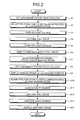
- the microscope controller 52 makes the revolver driver 42 arrange the objective lens 13 of a low magnification on the optical path of the microscope relative to the specimen S so that a wide area of the specimen S can be imaged (step S1).
- the microscope controller 52 makes the FS controller 45 adjust the field shutter 24 within the incident-light illumination optical system, or the field shutter 32 within the transmitting illumination optical system, and set an illumination area equal to the viewing field area of the objective lens 13 with a low magnification (step S2).
- the microscope controller 52 makes the illumination controller 43 turn on one of the incident-light illumination light source 22 and the transmitting illumination light source 31 corresponding to the field shutter 24 or 32 that is adjusted in step S2 (step S3).
- the imaging controller 51 gives an imaging command to the imaging unit 18, and in response, the imaging unit 18 images the specimen S via the objective lens 13 and generates the specimen image as a still image, which is a preliminary observation image (step S4).
- the microscope controller 52 makes the illumination controller 43 turn off one of the incident-light illumination light source 22 and the transmitting illumination light source 31 that is turned on in step S3 (step S5).
- one of the transmitting illumination optical system and the incident-light illumination optical system that is employed for imaging can illuminate the specimen S only for a time period the imaging unit 18 images the specimen S, since the microscope controller 52 controls the incident-light illumination light source 22 or the transmitting illumination light source 31 via the illumination controller 43. Further, since the microscope controller 52 makes the FS controller 45 adjust the field shutter 24 or the field shutter 32, only the imaging area of the imaging unit 18 on the specimen S can be illuminated.
- the imaging controller 51 displays an image display window 70 on the screen of the monitor 55 to present the specimen image as a still image inside the image display window 70 (step S6).
- the operation information management unit 53 displays a mouse pointer 72 on the screen of the monitor 55.
- the mouse pointer 72 serves to allow designation of a coordinate on the specimen image displayed in the image display window 70.
- a user moves the mouse pointer 72 through manipulation of a mouse included in the input device 56.
- clicking the mouse button for example, double clicks the mouse button
- the user can designate a coordinate on the specimen image displayed in the image display window 70.
- the microscope controller 52 arranges the objective lens 13 of a high magnification on the optical path of the microscope relative to the specimen S using the revolver driver 42 for the time-lapse imaging, which is a main observation (step S7).
- the operation information management unit 53 displays an imaging frame 73 on the specimen image displayed inside the image display window 70 as shown in FIG. 4 in response to a predetermined click manipulation of the mouse (for example, right-clicking for menu selection) (step S8).
- the imaging frame 73 has a size corresponding to an imaging magnification, i.e., a magnification of the currently selected objective lens 13.
- the imaging frame 73 represents an area of the specimen image which can be imaged by the imaging unit 18.
- the area corresponds to an observation area of the specimen S which is observed through the time-lapse imaging.
- the imaging frame 73 can be moved according to a dragging manipulation of the mouse by the user.
- the user can create a desired number of imaging frames 73, in other words, the operation information management unit 53 can display plural imaging frames 73.
- the operation information management unit 53 displays a popup menu, which is a menu of various commands, on the display screen of the monitor 55.
- the popup menu may include commands such as "Still” (command for generating one still image of a set brightness), "Movie” (command for generating a moving picture lasting for a predetermined time period), "Live” (command for displaying a live image), "Set” (command for setting a time-lapse imaging position), "Delete” (command for deleting an imaging frame), and "x 40" or "x60” (command for selecting a magnification).
- the microscope controller 52 stores a coordinate of a position on the specimen S corresponding to the position of the selected imaging frame 73 as the time-lapse imaging position, i.e., as a main observation position, in the imaging information database 60 inside the storage unit 58.
- the operation information management unit 53 deletes the selected imaging frame 73.
- the user can select the command "Live” for the display of live image to confirm the set position, and the command "Live” is not shown in the popup menu when the time-lapse imaging is executed.
- a caution message is displayed.
- the live image display is automatically cancelled.
- the operation information management unit 53 gives a command for imaging the area represented by the selected imaging frame 73.
- the microscope controller 52 makes the stage driver 41 drive the electromotive stage 12 based on the coordinate of the imaging frame 73 and arrange an area of the specimen S corresponding to the imaging frame 73 on the optical axis of the microscope so that the imaging position of the imaging unit 18 coincides with the area represented by the imaging frame 73 (step S9).
- the microscope controller 52 adjusts the field shutter 24 of the incident-light illumination optical system or the field shutter 32 of the transmitting illumination optical system using the FS controller 45, and sets an illumination area equal to the viewing field area of the objective lens 13 with a high magnification (step S10).
- the microscope controller 52 makes the illumination controller 43 turn on the incident-light illumination light source 22 or the transmitting illumination light source 31 corresponding to the field shutter 24 or 32 that is adjusted in step S10 (step S11).
- the imaging controller 51 gives an imaging command to the imaging unit 18, and the imaging unit 18 captures an image of the specimen S via the objective lens 13 and generates the specimen image (step S12).
- the microscope controller 52 makes the illumination controller 43 turn off the incident-light illumination light source 22 or the transmitting illumination light source 31 that is turned on in step S11 (step S13).
- the transmitting illumination optical system or the incident-light illumination optical system that is used for the imaging can illuminate the specimen S only for the period the imaging unit 18 captures an image of the specimen S, since the microscope controller 52 controls the incident-light illumination light source 22 or the transmitting illumination light source 31 using the illumination controller 43. Further, since the microscope controller 52 adjusts the field shutter 24 or the field shutter 32 via the FS controller 45, the transmitting illumination optical system or the incident-light illumination optical system can illuminate only the imaging area to be imaged by the imaging unit 18.
- the imaging controller 51 displays an enlarged display window 80 on the display screen of the monitor 55 as shown in FIG. 5, and displays the specimen image generated in step S12 within the enlarged display window 80 (step S14).
- the image displayed in the enlarged display window 80 is a still image when the command for capturing the still image is selected, and is a moving picture when the command for capturing the moving picture is selected.
- the imaging controller 51 displays the specimen image as the still image or the dynamic image on the display screen of the monitor 55 as captured from an area corresponding to the imaging frame 73 designated by the mouse pointer 72.
- the imaging unit 18 after capturing the image of the specimen S at the low magnification and generating the specimen image covering the wide area as a still image, captures the image of the specimen S at the high magnification at a imaging position changed by the microscope controller 52 and generates the specimen image as a still image or a dynamic image.
- the specimen image generated at first is a single still image covering a wider area than the specimen image generated later.
- the imaging controller 51 displays the enlarged display window 80 on the display screen of the monitor 55 separate from the image display window 70 in which the first generated specimen image of the low magnification is displayed.
- the imaging controller 51 displays the specimen image of the high magnification covering the area corresponding to the imaging frame 73 designated by the mouse pointer 72 inside the enlarged display window 80.
- the user can easily determine whether to set the currently selected imaging frame 73 as the time-lapse imaging position or not.
- the operation information management unit 53 can move the position of the selected imaging frame 73 to the position designated by the command information and display the imaging frame 73 at the corrected position. Specifically, as shown in FIG. 6, if the displayed imaging frame 73 runs across the cell to be observed (broken line in FIG. 6), the user can select the imaging frame 73 by the mouse pointer 72 and move by dragging, thereby correcting the position of the imaging frame 73 so as to enclose the cell inside (solid line in FIG. 6).
- the microscope controller 52 sets the coordinate of a central position, for example, of the selected imaging frame 73 as the coordinate of the selected imaging frame 73, and stores the coordinate as the time-lapse imaging position in the imaging information database 60 of the storage unit 58. Further, the microscope controller 52 stores at least one of the imaging condition of the imaging unit 18 and the illumination condition of the incident-light illumination optical system or the transmitting illumination optical system at the time the specimen image as the re-observation image is generated as the time-lapse imaging condition in the imaging information database 60.
- the imaging controller 51 executes the time-lapse imaging following the time-lapse imaging condition stored in the imaging information database 60.
- the microscope controller 52 positions the imaging position of the imaging unit 18 based on the time-lapse imaging position. Further, the imaging controller 51 makes the imaging unit 18 capture the image of the specimen S based on the time-lapse imaging condition and generate the specimen image.
- the microscope controller 52 stores the generated specimen image in the imaging information database 60 as a time-lapse specimen image.
- the user performs the screening while looking at the specimen image as a still image generated by the imaging of the wide area of the specimen S, and the specimen S is illuminated only during the period of the imaging. Therefore, compared with the method where the user performs the screening while looking at the live image, the time of the illumination of the specimen S is extremely short. Therefore, the illumination-induced discoloration and the damage of the specimen S can be well suppressed.
- the illumination area is restricted by the transmitting-type field shutter 24 or 32 so that only the imaging area of the specimen S to be imaged by the imaging unit 18 is illuminated.
- An illumination pattern can be alternatively formed by a reflective-type field shutter including a deflective mirror device (DMD).
- DMD deflective mirror device
- the specimen image of the wide area is first generated as a still image as the preliminary observation image and displayed on the image display window 70.
- the operation information management unit 53 configures a GUI for designating a brightness range of pixels to be displayed on the screen of the monitor 55, in addition to the GUIs described in relation with the first embodiment above, in cooperation with the monitor 55 and the input device 56. Therefore, a brightness range designating bar 75 is displayed in the image display window 70 as shown in FIG. 7A, so that the brightness range of the pixels displayed on the screen of the monitor 55 can be designated.
- the brightness range designating bar 75 has a slider 76 which reflects the brightness range of the pixels to be displayed on the screen of the monitor 55.
- a position and a length of the slider 76 are changeable through the dragging manipulation of the mouse.
- the imaging controller 51 extracts only the pixels with the brightness within the brightness range corresponding to the position and the length of the slider 76 from the first generated still specimen image, and displays the same on the image display window 70.
- FIG. 7B the lower end of the slider 76 shown in FIG. 7A is moved upward and the length of the slider 76 is made shorter. Accordingly, FIG. 7B shows an image with pixels of relatively high brightness as the display image within the image display window 70.
- the operation information management unit 53 displays a window 77 for the setting of the time-lapse imaging position in response to the predetermined click manipulation of the mouse (for example, menu selection by right click) as shown in FIG. 8.
- the window 77 includes MANUAL button for manual setting of the time-lapse imaging position and an Auto button for automatic setting of the time-lapse imaging position.
- the operation information management unit 53 displays the imaging frame 73 on the specimen image inside the image display window 70 as shown in FIG. 9, similarly to the first embodiment.
- the user can create a desired number of imaging frames 73 by performing the predetermined click manipulation of the mouse (for example, menu selection by right click).
- the imaging frame 73 has a size corresponding to the previously set high magnification of the objective lens 13, i.e., the imaging magnification, and the user can move the imaging frame 73 by dragging the mouse. For example, when the objective lens 13 with 40-fold magnification (x40) is set, the imaging frame 73 corresponding to the magnification (x40) is displayed. If the objective lens 13 is replaced later with one with 60-fold magnification (x60), the imaging frame 73 is changed accordingly and displayed in a small size.
- the operation information management unit 53 displays the popup menu including various commands on the screen of the monitor 55.
- the microscope controller 52 can store the coordinate of the position of the specimen S corresponding to the position of the selected imaging frame 73 as the time-lapse imaging position as the main observation position in the imaging information database 60 similarly to the first embodiment.
- the imaging controller 51 stores previously set imaging condition as the time-lapse imaging condition in the imaging information database 60.
- the operation information management unit 53 deletes the selected imaging frame 73.
- the operation information management unit 53 extracts regions of the currently displayed image in the image display window 70. Then, the operation information management unit 53 finds a central position of each extracted region and displays the imaging frame 73 around the found center as shown in FIG. 10.
- the imaging frame 73 has a size corresponding to the previously set high magnification of the objective lens 13, i.e., the imaging magnification, and the user.can move the imaging frame 73 by dragging the mouse.
- the microscope controller 52 stores a coordinate of a central position of the imaging frame 73, for example, as the coordinate of each imaging frame 73 in the imaging information database 60 of the storage unit 58 as the time-lapse imaging position.
- the imaging controller 51 further stores the previously set imaging condition in the imaging information database 60 in the storage unit 58 as the time-lapse imaging condition.
- the operation information management unit 53 displays the popup menu of various commands on the screen of the monitor 55.
- the commands included in the popup menu are, for example: "Still” for capturing a still image; “Movie” for capturing a moving picture; “Live” for displaying a live image; “Delete” for deleting the imaging frame; "x40” or "x60” for selecting the magnification.
- the operation information management unit 53 deletes the selected imaging frame 73, and the imaging information management unit 54 deletes the time-lapse imaging information corresponding to the selected imaging frame 73 from the imaging information database 60.
- the operation information management unit 53 gives a command to capture an image in an area corresponding to the selected imaging frame 73.
- the microscope controller 52 controls the electromotive stage 12 using the stage driver 41 based on the coordinate of the imaging frame 73 so that the imaging position of the imaging unit 18 coincides with the area of the currently selected imaging frame 73. Further, the microscope controller 52 adjusts the field shutter 24 of the incident-light illumination optical system or the field shutter 32 of the transmitting illumination optical system by the FS controller 45, to set the illumination area equal to the viewing field area of the objective lens 13 with a high magnification.
- the microscope controller 52 turns on the incident-light illumination light source 22 or the transmitting illumination light source 31 that corresponds to the adjusted field shutter 24 or 32 using the illumination controller 43.
- the imaging controller 51 gives an imaging command to the imaging unit 18.
- the imaging unit 18 captures an image of the specimen S via the objective lens 13 and generates the specimen image.
- the microscope controller 52 turns off the incident-light illumination light source 22 or the transmitting illumination light source 31 using the illumination controller 43.
- the transmitting illumination optical system or the incident-light illumination optical system that is used for the imaging can illuminate the specimen only while the imaging unit 18 captures the image of the specimen S, since the microscope controller 52 controls the incident-light illumination light source 22 or the transmitting illumination light source 31 via the illumination controller 43. Further, since the microscope controller 52 adjusts the field shutter 24 or the field shutter 32 using the FS controller 45, the transmitting illumination optical system or the incident-light illumination optical system that is used for the imaging can illuminate only the imaging area of the imaging unit 18.
- the imaging controller 51 displays the enlarged display window 80 on the screen of the monitor 55 and displays the generated specimen image inside the enlarged display window 80.
- the image displayed inside the enlarged display window 80 is a still image when the user selects the command for still image capturing, whereas the displayed image is a moving picture when the user selects the command for dynamic image capturing.
- textual information 82 is displayed together with the specimen image 81 of high magnification as shown in FIG. 11.
- the textual information 82 is related at least with one of an illumination condition such as intensity of illuminating light at the imaging of the specimen image 81, total time of illumination, total amount of illuminated light, and an imaging condition of the imaging unit 18.
- control unit 50 stores a set intensity of the incident-light illumination light source 22 and the transmitting illumination light source 31 in the storage unit 58, measures the illumination time by an internal counter and stores the measured time in the storage unit 58, and calculates the total amount of illuminated light based on the set intensity and the illumination time.
- the operation information management unit 53 gives a command to switch the objective lenses 13 to the microscope controller 52.
- the microscope controller 52 then switches the objective lens 13 to the one with a selected magnification using the revolver driver 42.
- the user performs the screening while looking at the specimen image as the still image generated by the imaging of a wide area, and the specimen S is illuminated only during the imaging. Therefore, the time the specimen S is illuminated is extremely short compared with the time the specimen S is illuminated when the user performs the screening while looking at the live image. Thus, the illumination-induced discoloration and the damage of the specimen can be well suppressed.
- the microscope controller 52 first arranges the objective lens 13 with a high magnification on the optical path of the microscope relative to the specimen S using the revolver driver 42.
- the microscope controller 52 shifts the electromotive stage 12 in a stepwise manner by a predetermined amount in the XY direction along a previously set path using the stage driver 41.
- the imaging controller 51 gives an imaging command to the imaging unit 18, and the imaging unit 18 captures the image of the specimen S via the objective lens 13 to generate the specimen image as a still image corresponding to a small section and having a high resolution as the preliminary observation image.
- One of the transmitting illumination optical system and the incident-light illumination optical system that is employed for the imaging illuminates the specimen S.only in an area of the imaging by the imaging unit 18 only while the imaging unit 18 captures the image of the specimen S every time the specimen S is moved stepwise, similarly to the first and the second embodiments.
- An amount of movement of one step is set, so that imaging areas of the imaging unit 18 before and after the stepwise moving of the specimen S are adjacent with each other, in other words, so that the specimen image generated before the stepwise moving is located next to the specimen image generated after the stepwise moving. Further, the stepwise moving is repeated vertically and horizontally until a finally obtained specimen image covers an entire desired area.
- the imaging position of the imaging unit 18 moves within the XY plane.
- the imaging position of the imaging unit 18 is moved, for example, as in raster scan.
- the imaging controller 51 stores the specimen image, which is a still image corresponding to a small section and having a high resolution, generated by the imaging unit 18 in the imaging information database 60 together with the imaging condition.
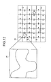
- the microscope controller 52 stores the coordinate of the imaging position at the time in the imaging information database 60. Further, the imaging controller 51 compresses and tiles each specimen image 85, which is a still image corresponding to a small section, having a high resolution, and generated by the imaging unit 18, as shown in FIG. 12, and displays the resulting image inside the image display window 70 on the screen of the monitor 55 as shown in FIG. 13.
- An arrow in FIG. 12 indicates an order of alignment of compressed images 86, and corresponds to a trajectory of the stepwise moving.
- the operation information management unit 53 in cooperation with the monitor 55 and the input device 56, forms a GUI for standing by for a selection of one of the plural compressed still images in addition to the GUIs described in relation to the first embodiment.
- the user shifts the mouse pointer 72 by manipulating the mouse, and performs the click manipulation (for example, double clicks the mouse button) on a desired compressed image 86.
- the click manipulation for example, double clicks the mouse button
- the imaging controller 51 displays the enlarged display window 80 on the screen of the monitor 55, reads out the specimen image 85, which is a still image corresponding to a small section and having a high resolution, corresponding to the designated compressed image 86 from the imaging information database 60, and displays the read-out specimen image 85 at an original magnification, i.e., in an original decompressed form on the enlarged display window 80.
- the operation information management unit 53 displays the popup menu on the screen of the monitor 55 in response to a predetermined click manipulation (for example, when the user right clicks the mouse button) similarly to the first and the second embodiments.
- the popup menu includes the command for setting the time-lapse imaging position.
- the microscope controller 52 stores the coordinate of the imaging position at the time the specimen image 85 corresponding to the compressed image 86 pointed by the mouse pointer 72 is generated, in the imaging information database 60 as the time-lapse imaging position as the main observation position.
- the microscope controller 52 stores at least one of an imaging condition of the imaging unit 18 at the time of generation of the specimen image 85 corresponding to the compressed image 86 pointed by the mouse pointer 72 and an illumination condition of the incident-light illumination optical system or the transmitting illumination optical system in the imaging information database 60 as the time-lapse imaging condition.
- the popup menu may include a command for still image capturing or a command for moving image capturing.
- the operation information management unit 53 gives a command to capture an image corresponding to an area designated by the selected imaging frame 73.
- the microscope controller 52 controls the electromotive stage 12 by the stage driver 41 so that the imaging position of the imaging unit 18 coincides with the imaging position at the time the specimen image 85 corresponding to the compressed image 86 pointed by the mouse pointer 72 is generated.
- the imaging controller 51 gives an imaging command to the imaging unit 18, and the imaging unit 18 captures the image of the specimen S via the objective lens 13 and generates the specimen image.
- the imaging controller 51 displays the enlarged display window 80 on the screen of the monitor 55 and displays the generated specimen image within the enlarged display window 80 without changing the magnification of the specimen image.
- the current specimen image of the position the user is interested in is displayed.
- z-stacking may be performed when the imaging position is moved in the XY direction in a stepwise manner and the imaging is to be performed.
- the imaging position of the imaging unit 18 is moved stepwise by a predetermined amount also in the Z direction, which is vertical to the XY plane, and thus plural still images are preliminary generated at each imaging position on the XY plane.
- the specimen S is illuminated only during the imaging. Therefore, the time the specimen S is illuminated is extremely short. Hence, the illumination-induced discoloration and damage of the specimen S can be well suppressed. In addition, since the high-resolution still images are previously taken, a time required for the screening can effectively be reduced, and the amount of illuminated light for the specimen S can effectively be reduced.
- a specimen image (hereinafter, "macro image") for screening is generated by capturing one specimen image as being a preliminary observation image through the low magnification objective lens 13 or by capturing plural specimen images to tile them.
- the fourth embodiment allows selection of a generation method for the macro image.
- the generation of the macro image and the designation of the time-lapse imaging position constitute a sequential screening procedure.
- the macro image is stored, and generation of the macro image and designation of the time-lapse imaging position are performed separately.
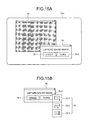
- FIG. 14 shows a main configuration of an observation apparatus of the fourth embodiment.
- the storage unit 58 further stores a macro image database 61 in addition to the components of the observation apparatus shown in FIG. 1.
- the operation information management unit 53 also serves as a preliminary imaging area controller.
- the other components are the same as those of the observation apparatus shown in FIG. 1, and the same components are denoted by the same reference characters.
- the operation information management unit 53 displays a selection window 78 for selecting a generation method for the macro images on a screen 55a of the monitor 55 according to generation instruction information for the generation of the macro image.
- the generation instruction information is input from, for example, the input device 56.
- the selection window 78 consists of a single button 78-1 and a tiling button 78-2.
- the single button 78-1 is for capturing a macro image through the low magnification objective lens 13 as in the first embodiment.
- the tiling button 78-2 is for tiling a specimen image captured through the high magnification objective lens 13 to generate a macro image.
- the user can select a generation method for the macro image by selecting the single button 78-1 or the tiling button 78-2 with, for example, a mouse.
- the operation information management unit 53 displays an imaging path selection button 79 on the screen 55a when the tiling button 78-2 is selected.
- the imaging path selection button 79 is for selecting an imaging path along which the specimen S is sequentially captured.
- the imaging path selection button 79 consists of a tornado button 79-1 for a tornado-like (vertex) scan, a raster button 79-2 for a raster scan (turn), and a one-way scan button 79-3 for a one-way scan. The user first selects one of these buttons with a mouse and the like to designate an imaging path.
- the imaging controller 51 controls the imaging unit 18 to capture an image of the specimen S according to the selected button to generate a macro image.
- the imaging controller 51 also stores the generated macro image in the macro image database 61 of the storage unit 58 every time the macro image is generated. Further, the imaging controller 51 stores the sequentially-tiled specimen images in association with each other as a group of the specimen S which forms a macro image in the macro image database 61.
- the microscope controller 52 stores at least one of an imaging condition, an illumination condition, and an imaging position in association with the macro image in the macro image database 61.
- the imaging condition is for the imaging unit 18 at capturing the specimen S to generate the macro image;
- the illumination condition is for the optical system used at capturing, i.e., the light-incident illumination optical system or the transmitting illumination optical system;
- the imaging position is a preliminary observation position on the specimen S.
- the microscope controller 52 stores at least an imaging position in association with each of the specimen images which forms a macro image. Accordingly, the microscope controller 52 can associate each of the specimen images which forms a macro image with the imaging position, i.e., the imaging path, and store the specimen images and the imaging positions in the macro image database 61.
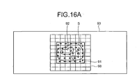
- FIG. 16A shows the specimen S placed on the electromotive stage 12, imaging areas on the specimen S each corresponding to one shot, and an imaging path.
- a tornado scan path is shown with arrows. It should be noted that the specimen S is placed on the electromotive stage 12 through a slide glass 90 and a cover slip 91 protects the upper portion of the specimen S.
- the imaging controller 51 controls the imaging unit 18 to sequentially capture the images of the image positions starting from an imaging starting position 92 every time the specimen S is shifted according to the arrows in a stepwise manner by the electromotive stage 12.
- the imaging controller 51 also displays the specimen image generated by the imaging unit 18 in the image display window 70 every time the image of each position is captured.
- the imaging controller 51 changes the display magnification for the group of the specimen images that are arranged in matrix form in the image display window 70 so that at least one pair of edges of the group of the specimen images comes into contact with an edge of the image display window 70. Specifically, as shown in FIG. 16-2, the imaging controller 51 arranges a sequence of specimen images in the image display window 70 while decreasing the display magnification according to the tornado imaging path.
- the imaging controller 51 first displays a specimen image 92a corresponding to the imaging position 92 over the image display window 70 (step 0).
- the imaging controller 51 next decreases the specimen image 92a and a specimen image 93a located in the right side of the specimen image 92a with half of the original magnification so that the left edge of the specimen image 92a and the right edge of the specimen image 93a come into contact with both edges of the image display window 70 (step 1).
- both specimen images are aligned upward in the image display window 70 and no specimen image areas of the image display window 70 are grayed out.
- the imaging controller 51 then maintains the display magnification until the specimen images fill the gray areas, specifically, until a specimen image 94a is displayed (step 3).
- the imaging controller 51 then decreases a specimen image 95a, which is generated right after the gray areas are filled, with two thirds of the current magnification (step 4).
- the group of the specimen images is displayed with the decreased display magnification so that the left edge, including the left edge of the specimen image 95a, of the group of the specimen images and the right edge, including the right edge of the specimen image 93a, of the group of the specimen images come into contact with the left and right edges of the image display window 70, respectively.
- These specimen images are also aligned downward in the image display window 70, and no specimen image areas are grayed out.
- the imaging controller 51 repeatedly displays a specimen image every time the specimen S is captured along the tornado scan path shown in FIG. 16A se steps are repeated.
- the imaging controller 51 finally displays a specimen image 96a so that a sequence of specimen images are tiled over the image display window 70 (step 35).
- the imaging controller 51 sets as one macro image an image consisting of the sequence of specimen images that have been generated on breaking off, and stores the macro image in the macro image database 61.
- the macro image consists of thirteen specimen images 92a to 97a which are tiled along the tornado scan path.
- the imaging controller 51 may sequentially display a sequence of specimen images along the raster scan path or the one-way scan path in the image display window 70 in the same manner as described above, to generate a macro image.
- the imaging controller 51 may also break off the generation of the macro image and store an incomplete macro image in the macro image database 61.
- the tornado scan path consists of thirty-five steps in FIG. 16, but not limited thereto.
- the tornado scan path can consist of any steps as long as it is not out of an allowable area 98 of the specimen S.
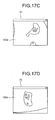
- the imaging controller 51 can store in advance a plurality of macro images generated as described above in the macro image database 61. Specifically, for example, for different imaging areas 101 to 103 in the specimen S as shown in FIG. 17A, macro images 101a to 103a may be generated and displayed in the image display window 70 as shown in FIG. 17B to 17D, and then stored in the macro image database 61. In this case, the microscope controller 52 stores each of the macro images 101a to 103a in association with at least one of an imaging condition, illumination condition, and imaging position in the macro image database 61.
- the operation information management unit 53 as being a preliminary imaging area controller displays a map image showing an observable area for the specimen S on the monitor 55, thereby allowing the user to designate a desired area on the map image to select an imaging area of a macro image.
- FIG. 18 shows a map image. As shown in FIG. 18, the operation information management unit 53 displays a map window 110 on a screen 55a of the monitor 55 according to selection instruction information for starting selection of an imaging position of the macro image.
- the selection instruction information is input from, for example, the input device 56.
- the operation information management unit 53 displays as a map image 111 either an image of the specimen S such as pseudo-observation image or super macro image or a frame indicating an observable area without an observation image.
- the pseudo-observation image is a rough observation image that is generated through a pre-observation of the specimen S;
- the super macro image is, for example, a low magnification specimen image that is generated through a extremely-low magnification objective lens 13.
- the user can designate a desired imaging area by specifying a desired position on the map image 111 through, for example, a click of a mouse included in the input device 56 while viewing the map image 111 on the screen 55a.
- the operation information management unit 53 sets the position as a center and superimposes a rectangular frame mark with a predetermined size onto the image map 111. Accordingly, the operation information management unit 53 clearly shows the imaging area of the macro image corresponding to the position information on the map image 111.
- FIG. 18 shows frame marks 112 to 114 as examples of the superimposing mark. If a macro image is generated by tiling specimen images generated through the high magnification objective lens 13, the size of each frame mark is set based on the observation magnification of the observation optical system and the number of tiled specimen images.
- the operation information management unit 53 modifies the position of a frame mark including the overlapping area, in other words, the position of at least one imaging area, to eliminate overlapping. As a result, the operation information management unit 53 can avoid multiple imaging and multiple exposure over all areas in the specimen S at the generation of a macro image.
- the operation information management unit 53 can store imaging area information indicating the imaging area of the macro image set as described above in the macro image database 61 through the storage unit 58.
- the observation apparatus according to the fourth embodiment can thus generate macro images after setting the imaging areas of all the macro images.
- the imaging controller 51 generate the macro images sequentially based on the imaging area information stored in the macro image database 61.
- the imaging controller 51 may generate a macro image corresponding to the imaging area every time the imaging area of the macro image is designated.
- FIG. 19 shows a display image used for explaining the display method.
- the imaging controller 51 displays a macro image selection window 120 on a screen 55a of the monitor 55 and thumbnails the macro images 121 stored in the macro image database 61 in the macro image selection window 120, according to display instruction information for displaying a macro image.
- the display instruction information is input from, for example, the input device 56.
- the imaging controller 51 scrolls the macro images in the macro image selection window 120.
- the macro images 121 can be scrolled up or down with a slide bar 122 slid by dragging a mouse included in the input device 56.
- the imaging controller 51 also overlays condition information 123 as textual information onto each macro image 121.
- the condition information 123 indicates at least one of the imaging condition, the illumination condition, and the imaging position which are each stored in association with the macro image in the macro image database 61.
- the overlaid information can be hidden according to predetermined instruction information input from the input device 56.
- the imaging controller 51 may display a pop-up of the condition information 123 in place of the overlaid condition information 123. For example, the imaging controller 51 can pop-up the condition information 123 corresponding to the macro image, which is selected by double-clicking the mouse button with a mouse pointer 72 positioned on the macro image 121.
- the imaging controller 51 can also enlarge the selected macro image 121 in the image display window 70.
- the condition information 123 may be overlaid or displayed as a pop-up on the enlarged macro image.
- the observation apparatus can store the macro image generated for screening procedure in the macro image database 61, so that the user can designate a time-lapse imaging position at a desired timing by reading the macro image from the macro image database 61, without performing the generation of the macro image and the designation of the time-lapse imaging position sequentially.
- the observation apparatus can also store plural macro images, which allows generation of plural macro images in advance before the screening procedure. As a result, workability and efficiency of the screening procedure can be improved. This improvement leads to improvement of accuracy of the screening procedure.
- the observation apparatus can repeatedly designate the time-lapse position, thereby reducing damages to the specimen S at screening.
- the conventional observation apparatus generates a macro image every time the time-lapse imaging position is designated, and illuminates the specimen S with an illumination light every generation of the macro image, because such a observation apparatus does not store any macro images. As a result, the specimen S is damaged or discolored every illumination.
- the observation apparatus according to the fourth embodiment can reduce illumination of the specimen S and damages to the specimen S by storing the macro images.
- the observation apparatus also allows designation of the imaging position of a macro image on the map image 111, thereby reducing damages to the specimen S at the designation procedure. If no map image 111 is used, the user has to designate the imaging area of a macro image while viewing live images of the specimen S, in other words, while the specimen S is continuously illuminated with an illumination light during the designation procedure. This leads to heavy damages to the specimen S.
- the observation apparatus according to the fourth embodiment does not require to illuminate the specimen S during the designation of the imaging area of a macro image, thereby reducing damages to the specimen S drastically. In the designation procedure using the map image 111, since the plural macro images do not overlap, the specimen S is not multiply exposed in the generation of the macro image, thereby reducing damages due to the exposure.
- the user may designate an imaging area of a macro image while viewing live images of the specimen S, if necessary.
- the specimen S is automatically scanned along a predetermined path with the electromotive stage 12, and receives predetermined designation information when a desired area in the specimen S is displayed in the live image, so that the desired area is designated as the imaging area of the macro image.
- the observation apparatus can use an appropriate generation method for each specimen S or each observation or each objective lens 13, because the observation apparatus allows the user to select one of the generation methods for the macro image. Accordingly, the accuracy of the screening procedure can be improved as well as the accuracies of and the time-lapse imaging and the observation result based on the time-lapse imaging can be improved.
Landscapes
- Physics & Mathematics (AREA)
- Health & Medical Sciences (AREA)
- Multimedia (AREA)
- Chemical & Material Sciences (AREA)
- Analytical Chemistry (AREA)
- Engineering & Computer Science (AREA)
- General Physics & Mathematics (AREA)
- Optics & Photonics (AREA)
- Nuclear Medicine, Radiotherapy & Molecular Imaging (AREA)
- Computer Vision & Pattern Recognition (AREA)
- Life Sciences & Earth Sciences (AREA)
- Biochemistry (AREA)
- General Health & Medical Sciences (AREA)
- Immunology (AREA)
- Pathology (AREA)
- Microscoopes, Condenser (AREA)
- Studio Devices (AREA)
Applications Claiming Priority (3)
| Application Number | Priority Date | Filing Date | Title |
|---|---|---|---|
| JP2005268617 | 2005-09-15 | ||
| JP2006202229 | 2006-07-25 | ||
| JP2006238894A JP2008052227A (ja) | 2005-09-15 | 2006-09-04 | 観察装置 |
Publications (2)
| Publication Number | Publication Date |
|---|---|
| EP1764640A2 true EP1764640A2 (fr) | 2007-03-21 |
| EP1764640A3 EP1764640A3 (fr) | 2007-04-18 |
Family
ID=37499555
Family Applications (1)
| Application Number | Title | Priority Date | Filing Date |
|---|---|---|---|
| EP20060019198 Ceased EP1764640A3 (fr) | 2005-09-15 | 2006-09-13 | Microscope accélérateur pour imagerie multipoint |
Country Status (3)
| Country | Link |
|---|---|
| US (1) | US20070058054A1 (fr) |
| EP (1) | EP1764640A3 (fr) |
| JP (1) | JP2008052227A (fr) |
Cited By (5)
| Publication number | Priority date | Publication date | Assignee | Title |
|---|---|---|---|---|
| EP2194415A2 (fr) | 2008-12-08 | 2010-06-09 | Olympus Corporation | Système d'imagerie pour microscope et système de microscope |
| EP2196841A1 (fr) | 2008-12-12 | 2010-06-16 | Olympus Corp. | Appareil d'imagerie microscopique et procédé d'imagerie microscopique |
| EP2345921A2 (fr) * | 2010-01-07 | 2011-07-20 | Sanyo Electric Co., Ltd. | Dispositif de commande, programme de commande et procédé de commande pour unité d'observation et système d'observation |
| US8179433B2 (en) | 2008-12-11 | 2012-05-15 | Olympus Corporation | Microscopic imaging apparatus and microscopic imaging method |
| EP2533092A1 (fr) * | 2010-02-03 | 2012-12-12 | Nikon Corporation | Dispositif d'observation et procédé d'observation |
Families Citing this family (28)
| Publication number | Priority date | Publication date | Assignee | Title |
|---|---|---|---|---|
| JP4873917B2 (ja) * | 2005-09-28 | 2012-02-08 | オリンパス株式会社 | 走査型レーザ顕微鏡装置 |
| US8264768B2 (en) * | 2007-06-07 | 2012-09-11 | Olympus Corporation | Microscope system |
| JP5185769B2 (ja) * | 2008-10-22 | 2013-04-17 | オリンパス株式会社 | 顕微鏡システム |
| JP5365691B2 (ja) * | 2009-04-10 | 2013-12-11 | 株式会社ニコン | 生体試料観察装置 |
| JP2010263465A (ja) * | 2009-05-08 | 2010-11-18 | Seiko Epson Corp | 画像読取装置および画像読取方法 |
| JP5343762B2 (ja) * | 2009-08-25 | 2013-11-13 | 株式会社ニコン | 制御装置、およびその制御装置を用いた顕微鏡システム |
| JP5591007B2 (ja) * | 2009-11-20 | 2014-09-17 | オリンパス株式会社 | 顕微鏡装置 |
| CN102792151B (zh) | 2010-03-23 | 2015-11-25 | 加州理工学院 | 用于2d和3d成像的超分辨率光流体显微镜 |
| US9643184B2 (en) | 2010-10-26 | 2017-05-09 | California Institute Of Technology | e-Petri dishes, devices, and systems having a light detector for sampling a sequence of sub-pixel shifted projection images |
| EP2633267A4 (fr) | 2010-10-26 | 2014-07-23 | California Inst Of Techn | Système de microscope sans lentille à projections et balayage |
| US9569664B2 (en) * | 2010-10-26 | 2017-02-14 | California Institute Of Technology | Methods for rapid distinction between debris and growing cells |
| KR20140027113A (ko) | 2011-03-03 | 2014-03-06 | 캘리포니아 인스티튜트 오브 테크놀로지 | 도광 픽셀 |
| JP5814709B2 (ja) * | 2011-09-12 | 2015-11-17 | オリンパス株式会社 | タイムラプス観察方法、及び、それに用いられるタイムラプス観察装置 |
| EP2857884B1 (fr) * | 2012-05-28 | 2021-05-05 | Sony Corporation | Dispositif, procédé et programme de traitement d'informations, et système de microscope |
| JP6278601B2 (ja) * | 2013-02-15 | 2018-02-14 | オリンパス株式会社 | 顕微鏡システム及びプログラム |
| JP2014178403A (ja) * | 2013-03-14 | 2014-09-25 | Sony Corp | デジタル顕微鏡装置、情報処理方法、および情報処理プログラム |
| JP6455829B2 (ja) * | 2013-04-01 | 2019-01-23 | キヤノン株式会社 | 画像処理装置、画像処理方法、およびプログラム |
| JP6378869B2 (ja) * | 2013-10-24 | 2018-08-22 | 株式会社キーエンス | 顕微鏡、顕微鏡システム、制御方法およびプログラム |
| CN105849635B (zh) | 2013-12-27 | 2018-07-10 | 富士胶片株式会社 | 摄像装置及延时摄像方法 |
| EP2942941B1 (fr) * | 2014-05-08 | 2016-04-27 | Axis AB | Procédé et appareil pour déterminer un besoin de changement dans une exigence de densité de pixels due au changement des conditions de lumière |
| WO2016101092A1 (fr) | 2014-12-22 | 2016-06-30 | 杭州唐光科技有限公司 | Microscope numérique et son procédé de mise au point |
| CN105785561B (zh) * | 2014-12-22 | 2018-04-03 | 杭州舜立光电科技有限公司 | 一种数字显微镜及其聚焦方法 |
| JP6333871B2 (ja) * | 2016-02-25 | 2018-05-30 | ファナック株式会社 | 入力画像から検出した対象物を表示する画像処理装置 |
| CN105938243B (zh) * | 2016-06-29 | 2018-04-13 | 华南理工大学 | 一种tft‑lcd检测中多倍率显微镜快速对焦方法 |
| CN106291899A (zh) * | 2016-09-29 | 2017-01-04 | 东方晶源微电子科技(北京)有限公司 | 照明模块、光学显微系统及电子束检测装置 |
| JP6906992B2 (ja) * | 2017-03-24 | 2021-07-21 | オリンパス株式会社 | 表示制御システム、表示制御方法、及び、プログラム |
| US10473908B2 (en) * | 2017-04-21 | 2019-11-12 | Shimadzu Corporation | Optical observation device |
| JP7060394B2 (ja) * | 2018-02-14 | 2022-04-26 | オリンパス株式会社 | 顕微鏡システム、表示制御方法、及び、プログラム |
Citations (1)
| Publication number | Priority date | Publication date | Assignee | Title |
|---|---|---|---|---|
| DE19812599A1 (de) * | 1998-03-23 | 1999-09-30 | Leica Microsystems | Verfahren zur Video-Mikroskopie |
Family Cites Families (10)
| Publication number | Priority date | Publication date | Assignee | Title |
|---|---|---|---|---|
| US6738558B2 (en) * | 1996-10-24 | 2004-05-18 | Leica Microsystems Wetzlar Gmbh | Microscope with a proximity sensor |
| ATE268008T1 (de) * | 1997-02-27 | 2004-06-15 | Cellomics Inc | Ein system zur zellbasierten reihenuntersuchung |
| US6400502B1 (en) * | 1998-08-18 | 2002-06-04 | Nikon Corporation | Microscope |
| ATE249657T1 (de) * | 2000-04-06 | 2003-09-15 | European Molecular Biology Lab Embl | Rechnergesteuertes mikroskop |
| US6798571B2 (en) * | 2001-01-11 | 2004-09-28 | Interscope Technologies, Inc. | System for microscopic digital montage imaging using a pulse light illumination system |
| JP4497923B2 (ja) * | 2001-12-05 | 2010-07-07 | ザ ジェイ. デビッド グラッドストーン インスティテューツ | ロボット顕微鏡検査システム |
| JP4014916B2 (ja) * | 2002-04-11 | 2007-11-28 | 株式会社キーエンス | 電子顕微鏡、電子顕微鏡の操作方法、電子顕微鏡操作プログラムおよびコンピュータで読み取り可能な記録媒体 |
| US20030210262A1 (en) * | 2002-05-10 | 2003-11-13 | Tripath Imaging, Inc. | Video microscopy system and multi-view virtual slide viewer capable of simultaneously acquiring and displaying various digital views of an area of interest located on a microscopic slide |
| JP2004101871A (ja) * | 2002-09-10 | 2004-04-02 | Olympus Corp | 顕微鏡画像撮影装置 |
| US7030351B2 (en) * | 2003-11-24 | 2006-04-18 | Mitutoyo Corporation | Systems and methods for rapidly automatically focusing a machine vision inspection system |
-
2006
- 2006-09-04 JP JP2006238894A patent/JP2008052227A/ja not_active Withdrawn
- 2006-09-13 EP EP20060019198 patent/EP1764640A3/fr not_active Ceased
- 2006-09-14 US US11/521,117 patent/US20070058054A1/en not_active Abandoned
Patent Citations (1)
| Publication number | Priority date | Publication date | Assignee | Title |
|---|---|---|---|---|
| DE19812599A1 (de) * | 1998-03-23 | 1999-09-30 | Leica Microsystems | Verfahren zur Video-Mikroskopie |
Non-Patent Citations (1)
| Title |
|---|
| "Contrast Manipulation - Specimen Illumination ED - Sluder G; Wolf D", 1 January 2003, METHODS IN CELL BIOLOGY,, PAGE(S) 85,190 - 261,383, ISBN: 0-12-564169-9, XP007923093 * |
Cited By (13)
| Publication number | Priority date | Publication date | Assignee | Title |
|---|---|---|---|---|
| EP2194415A3 (fr) * | 2008-12-08 | 2010-07-28 | Olympus Corporation | Système d'imagerie pour microscope et système de microscope |
| EP2194415A2 (fr) | 2008-12-08 | 2010-06-09 | Olympus Corporation | Système d'imagerie pour microscope et système de microscope |
| US8259171B2 (en) | 2008-12-08 | 2012-09-04 | Olympus Corporation | Digital camera system for microscope and microscope system, where output depends on change in observation magnification after measurement value is displayed |
| US8179433B2 (en) | 2008-12-11 | 2012-05-15 | Olympus Corporation | Microscopic imaging apparatus and microscopic imaging method |
| EP2196841A1 (fr) | 2008-12-12 | 2010-06-16 | Olympus Corp. | Appareil d'imagerie microscopique et procédé d'imagerie microscopique |
| EP2345921A2 (fr) * | 2010-01-07 | 2011-07-20 | Sanyo Electric Co., Ltd. | Dispositif de commande, programme de commande et procédé de commande pour unité d'observation et système d'observation |
| EP2345921A3 (fr) * | 2010-01-07 | 2012-04-04 | Sanyo Electric Co., Ltd. | Dispositif de commande, programme de commande et procédé de commande pour unité d'observation et système d'observation |
| US8773520B2 (en) | 2010-01-07 | 2014-07-08 | Panasonic Healthcare Co., Ltd. | Control device, control program, and control method for observation unit, and observation system |
| EP2533092A1 (fr) * | 2010-02-03 | 2012-12-12 | Nikon Corporation | Dispositif d'observation et procédé d'observation |
| EP2533092A4 (fr) * | 2010-02-03 | 2013-07-17 | Nikon Corp | Dispositif d'observation et procédé d'observation |
| US9927605B2 (en) | 2010-02-03 | 2018-03-27 | Nikon Corporation | Time lapse shooting apparatus and observation method |
| US10634151B2 (en) | 2010-02-03 | 2020-04-28 | Nikon Corporation | Time lapse shooting apparatus and observation method |
| US11236755B2 (en) | 2010-02-03 | 2022-02-01 | Nikon Corporation | Time lapse shooting apparatus and observation method |
Also Published As
| Publication number | Publication date |
|---|---|
| EP1764640A3 (fr) | 2007-04-18 |
| JP2008052227A (ja) | 2008-03-06 |
| US20070058054A1 (en) | 2007-03-15 |
Similar Documents
| Publication | Publication Date | Title |
|---|---|---|
| EP1764640A2 (fr) | Microscope accélérateur pour imagerie multipoint | |
| US7822257B2 (en) | Observation apparatus and observation method | |
| EP1691230B2 (fr) | Dispositif photo-micrographique et procédé de contrôle | |
| JP4917329B2 (ja) | 画像取得装置、画像取得方法、及び画像取得プログラム | |
| US7929738B2 (en) | Microscope apparatus and microscope system | |
| US10139613B2 (en) | Digital microscope and method of sensing an image of a tissue sample | |
| JP4937850B2 (ja) | 顕微鏡システム、そのvs画像生成方法、プログラム | |
| US20070064101A1 (en) | Observation apparatus | |
| JP4878914B2 (ja) | 顕微鏡システム、顕微鏡の制御方法、及びプログラム | |
| JP2004101871A (ja) | 顕微鏡画像撮影装置 | |
| EP2804039B1 (fr) | Système de microscope et procédé pour décider de la zone piquée | |
| JP4878815B2 (ja) | 顕微鏡装置 | |
| JP2007233094A (ja) | 画像取得装置、画像取得方法、及び画像取得プログラム | |
| US10613313B2 (en) | Microscopy system, microscopy method, and computer-readable recording medium | |
| JP4847101B2 (ja) | 顕微鏡システム | |
| US7865007B2 (en) | Microscope system, observation method and observation program | |
| JP2005266718A (ja) | 顕微鏡画像撮影システム |
Legal Events
| Date | Code | Title | Description |
|---|---|---|---|
| PUAI | Public reference made under article 153(3) epc to a published international application that has entered the european phase |
Free format text: ORIGINAL CODE: 0009012 |
|
| PUAL | Search report despatched |
Free format text: ORIGINAL CODE: 0009013 |
|
| AK | Designated contracting states |
Kind code of ref document: A2 Designated state(s): AT BE BG CH CY CZ DE DK EE ES FI FR GB GR HU IE IS IT LI LT LU LV MC NL PL PT RO SE SI SK TR |
|
| AX | Request for extension of the european patent |
Extension state: AL BA HR MK YU |
|
| AK | Designated contracting states |
Kind code of ref document: A3 Designated state(s): AT BE BG CH CY CZ DE DK EE ES FI FR GB GR HU IE IS IT LI LT LU LV MC NL PL PT RO SE SI SK TR |
|
| AX | Request for extension of the european patent |
Extension state: AL BA HR MK YU |
|
| 17P | Request for examination filed |
Effective date: 20071008 |
|
| AKX | Designation fees paid |
Designated state(s): DE |
|
| 17Q | First examination report despatched |
Effective date: 20140610 |
|
| RAP1 | Party data changed (applicant data changed or rights of an application transferred) |
Owner name: OLYMPUS CORPORATION |
|
| RAP1 | Party data changed (applicant data changed or rights of an application transferred) |
Owner name: OLYMPUS CORPORATION |
|
| STAA | Information on the status of an ep patent application or granted ep patent |
Free format text: STATUS: THE APPLICATION HAS BEEN REFUSED |
|
| 18R | Application refused |
Effective date: 20160630 |