EP1764432B1 - Yarn feeder of yarn feeding device in weft knitting machine - Google Patents
Yarn feeder of yarn feeding device in weft knitting machine Download PDFInfo
- Publication number
- EP1764432B1 EP1764432B1 EP05751163.6A EP05751163A EP1764432B1 EP 1764432 B1 EP1764432 B1 EP 1764432B1 EP 05751163 A EP05751163 A EP 05751163A EP 1764432 B1 EP1764432 B1 EP 1764432B1
- Authority
- EP
- European Patent Office
- Prior art keywords
- yarn
- yarn feeding
- feeder
- selection lever
- entraining
- Prior art date
- Legal status (The legal status is an assumption and is not a legal conclusion. Google has not performed a legal analysis and makes no representation as to the accuracy of the status listed.)
- Expired - Lifetime
Links
Images


Classifications
-
- D—TEXTILES; PAPER
- D04—BRAIDING; LACE-MAKING; KNITTING; TRIMMINGS; NON-WOVEN FABRICS
- D04B—KNITTING
- D04B15/00—Details of, or auxiliary devices incorporated in, weft knitting machines, restricted to machines of this kind
- D04B15/38—Devices for supplying, feeding, or guiding threads to needles
- D04B15/54—Thread guides
- D04B15/56—Thread guides for flat-bed knitting machines
-
- D—TEXTILES; PAPER
- D04—BRAIDING; LACE-MAKING; KNITTING; TRIMMINGS; NON-WOVEN FABRICS
- D04B—KNITTING
- D04B15/00—Details of, or auxiliary devices incorporated in, weft knitting machines, restricted to machines of this kind
- D04B15/38—Devices for supplying, feeding, or guiding threads to needles
- D04B15/54—Thread guides
-
- D—TEXTILES; PAPER
- D04—BRAIDING; LACE-MAKING; KNITTING; TRIMMINGS; NON-WOVEN FABRICS
- D04B—KNITTING
- D04B7/00—Flat-bed knitting machines with independently-movable needles
- D04B7/24—Flat-bed knitting machines with independently-movable needles for producing patterned fabrics
- D04B7/26—Flat-bed knitting machines with independently-movable needles for producing patterned fabrics with colour patterns
Definitions
- the present invention relates to a yarn feeder of a yarn feeding device for a weft knitting machine, in which a yarn feeding port of the yarn feeder put on standby at an end of the knitting fabric or at a changed portion of the knitting pattern, for example, an intarsia knitting pattern, can be switched over to a position outside the fabric knitting region.
- a yarn feeder associated with a carriage to feed yarn to a needle of a needle bed for knitting the fabric is kept at a standby position outside the knitting region.
- the position of the knitting yarn is lowered proportionately so that it becomes able to catch reliably the yarn in a hook of needle.
- such a yarn feeder is released from the entraining device at a position exceeding the boundary with the boundary with the adjacent knitting region.
- the yarn extending between the yarn feeder that has stopped inside the adjoining knitting region and the knitted fabric may obstruct the subsequent knitting operation in the next knitting region.
- such a yarn feeder of a weft knitting machine comprising a switching mechanism for switch-swinging the position of the yarn feeding port installed in a feeder case, the switching mechanism further comprising a pressing operation part switch-operating the swinging direction and altitude of the yarn feeding port in association, wherein the said yarn feeder is capable of obtaining the same effect as in a case in which the amount of swinging of a yarn feeder is substantially increased without increasing the amount thereof (See Patent Document 1).
- the yarn feeding port of the yarn feeder largely swings to the left or the right on its standby position so that the yarn drawn from the stitch at the end of the knitting region will be pulled up. Therefore, there was a fear that it might happened clogging of the stitch at the end of the knitting region and become very hard to form a uniform stitch therein.
- the present invention has been proposed in consideration of the aforementioned problems. It is therefore an object of the present invention to provide a yarn feeder of a yarn feeding device used for a weft knitting machine, which is capable of producing a fabric having uniform stitches with high productivity without increasing the size of the yarn feeder.
- a yarn feeder of a yarn feeding device used for a weft knitting machine in which a plurality of yarn feeders which are engaged with and to be slide on knitting yarn guide rails arranged over a needle bed, an entraining means for entraining selectively any one of the yarn feeders and a switching mechanism for changing over the swing of a yarn feeding port provided at a lower end of a feeder rod between a yarn feeding position and a standby position interlocking with the operation of the entraining means, wherein before the selected yarn feeder through the operation of the entraining means having been entrained from a standby position to a yarn feeding position, the switching mechanism is operated so as to swing the yarn feeding port from the standby position to the yarn feeding position while, after having completed yarn feeding operation, the yarn feeding port being swung from one yarn feeding position to another standby position interlocking with the released selective operation of the entraining means, the yarn feeder being primarily characterized in that: the switching mechanism comprises a selection
- a yarn feeder according to the present invention is characterized in that the feeder rod forms a holding member that elastically holds a position set by one of the oblique surfaces and the receiving portion on the selection lever.
- the switching mechanism comprises a selection lever pivoted to be enabled to swing, the selection lever being formed of two oblique surfaces each setting a swinging direction of the feeder rod and a receiving portion at an intermediate portion between the oblique surfaces for gripping the feeder rod at a neutral position in an upright position, and substantially formed in a T-like shape; and a neutral holding mechanism which comprises an operation device composed of a pair of links to be activated in association with the entraining means, is provided, wherein when the operation device being activated, portions adjacent to the middle of the selection lever are pushed up and swung by the pair of links respectively so that the receiving portion of the selection lever holds the upper end of the feeding rod upright state in the neutral position with making the upper end of the feeding rod confronted with the receiving portion of the selection lever, the yarn feeding port of the yarn feeder in the standby position is eliminated from greatly swinging horizontally as aforesaid proposals. Therefore, the knitting yarn extended from the stitch of the end of the knitting region in the knitted fabric can be prevented
- the position of the yarn feeding port does not become higher. Therefore, this will advantageously allow the knitting yarn upon transfer of stitch or increase in the stitch at the end of the knitting region to reach the back surface of the needle.
- the yarn feeder does not have to be greatly slid out of the knitting region, it can be given advantageous improvement of the productivity by reducing the sliding distance of the yarn feeder.
- the switching mechanism is provided with the neutral position holding mechanism for holding the yarn feeding port at a low neutral position adjacent to the needle in the standby state of the yarn feeder. This will provide advantages for preventing the increase in size of the yarn feeder, resulting in the compact structure.
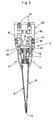
- Fig. 1 is a lateral view of a weft knitting machine having a yarn feeding device including yarn feeders of the present invention, wherein a reference numeral 1 denotes the weft knitting machine in its entirety, and 2 denotes the yarn feeding device.
- the weft knitting machine 1 has a pair of front and rear needle beds 3 disposed on a frame 4 in a fan shape with extreme ends thereof confronting each other, and each needle bed 3 has a plurality of knitting needles 5 thereon in parallel with each other so that they are movable back and force.
- a carriage 6 is disposed on an upper surface of each needle bed 3 so that it can be caused to reciprocate by a belt drive device (not shown).
- a bat 48 of each knitting needle 5 is operated by a knitting cam 7 attached to the carriage 6 as shown in the drawing so as to be advanced and retracted.
- a gate arm (slide drive mechanism) 8 is mounted on the carriages 6 so as to stride over the front and back needle beds 3, and is integrally coupled with the carriages 6.
- a gate arm 8 mounted on the gate arm 8 are a entraining device 10 that brings yarn feeders 9, and a push-down member 13 that pushes down yarn feeding ports 12 of the yarn feeders 9 to positions adjacent to each extreme end of the knitting needles 5 and 5.
- Four knitting yarn guide rails 11 are elongated longitudinally over the needle beds 3 and arranged backward and forward over there in the form of a fan at the position in the radical direction apart from the center nearly close to the extreme one end of the knitting needles 5 disposed in parallel with each other on the needle beds 3.
- the entraining device 10 includes transmission rods 15 for transmitting movement of output shafts of solenoids, which are projected and retracted in response to a signal output from a controller (not shown) to entraining pins 14 as shown in Fig. 2 .
- the entraining pins 14 are forced downward by means of springs 16 engaged into engagement portions 19 which are formed respectively on a pair of right and left swinging pieces 18 disposed on a feeder case 17 of the respective yarn feeder 9 at portions adjacent to the center of upper end thereof. In this way, the yarn feeders 9 are fed by the entraining pins 14 (see Fig. 3 ).
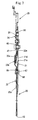
- the yarn feeder 9 is composed of a feeder case 17 supported by the knitting yarn guide rail 11 to be able to slide thereon, a feeder rod 20 provided with the yarn feeding port 12 at its lower end and suspended from the lower end portion of the feeder case 17, and a neutral position holding mechanism that hangs a feeder rod guide 21 for guiding the feeder rod 20 and holds the yarn feeding ports 12 to neutral state in the standby position.
- An upper pivot portion of the feeder rod guide 21 is pivoted to the feeder case 17 to be able to swing horizontally.
- the feeder rod 20 is formed of a slender sheet-shaped lower plate 22 whose right and left side edge portions are supported by the feeder rod guide 21 to be able to slide upward and downward, an intermediate plate 23 whose lower end portion is moveably coupled with an upper end portion of the lower plate 22, and an upper plate 25 whose lower end portion is coupled with the intermediate plate 23 through a push-down roller 24 projecting from an upper back surface of the intermediate plate 23.
- the push-down roller 24 is engaged with a lateral slot 26 formed at a lower end portion of the upper plate 25.
- coil springs 27 are mounted on the coil receiving portions 28 of the feeder case 17 with the middle plate 23 and the lower plate 22 so as to forcibly move the upper plate 25 up and down.
- the lower plate 22 includes a yarn feeding port forming member 22a, a spring storage member 22b interposed between the lower plate 22 and the feeder rod guide 21 at a portion above the yarn feeding port forming member 22a, compression springs 22c stored in the spring storage member 22b, and a receiving portion 22d that is engaged with an engagement hole 21a of the feeder rod guide 21 and receives the lower end of the compression spring (urging portion) 22c.
- An abutment portion 22e that abuts against a regulation portion 46 (described later) is formed at the upper end of the spring storage member 22b such that the lower plate 22 is urged upward by the compression spring 22.
- the regulation portion 46 that abuts against the abutment portion 22e is formed of a dice-like member 47 fixed to be tightened to the feeder case 17 together with the feeder rod guide 21 through a sliding slot 23a (see Figs. 5 , 6 , and 7 ).
- the slot 65 formed through the yarn feeding port forming member 22a of the lower plate 22 being associated with a hole 66 formed through the upper end of the spring storage member 22b by means of fixtures 67, for example, bolts and nuts, it is capable of adjusting a position of the lower plate 22 by loosening the fixture 67 to be adjustable in a altitude of the yarn feeding port 12 (refer to Figs. 3 and 4 ).
- a switching roller 30 of a switching mechanism 29 for switching a position of the yarn feeding port 12 projects from a front surface of the intermediate plate 23 at an upper end portion thereof.
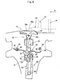
- the switching mechanism 29 includes the switching roller 30, a regulation hole 31 formed through the feeder case 17 for regulating a swing motion of the switching roller 30, and a selection lever 32 disposed on a back surface side of the regulation hole 31.
- the regulation hole 31 is formed in substantially a trifoliate shape having spaces with which the switching roller 30 is engaged at the center, upper left and upper right portions thereof.
- the selection lever 32 that sets an upward moving direction of the switching roller 30 confronting the regulation hole 31 is formed in substantially a T-shape with its upper end portion 32a formed in a gentle V-shape.
- the selection lever 32 is pivoted to the feeder case 17 at a pivot portion 32b at the center, which hangs down from a center of the upper end portion 32a and terminates in an arrow shape having oblique surfaces 34 and 34 on the right and left sides thereof for directing the upward moving direction of the switching roller 30.
- the intermediate portion between the oblique surfaces 34 and 34 has a roller receiving portion 35 that receives the switching roller 30 in a neutral position.
- a holding means 36 for holding the switched positions of the selection lever 32 is disposed at an upper portion of an arrow-shaped portion formed of the two oblique surfaces 34 and 34 and the roller receiving portion 35.
- the holding means 36 is arranged such that mustache-like elastic portions 37 are extended in both horizontal directions from an upper portion of the arrow-like portion, and gripping portions 38 and 39 are formed by bending portions near extreme ends of the elastic portions 37. Further engaging projections 40 are formed on a back surface of the feeder case 17 such that any one of them is engaged with any one of the gripping portions 38 and 39 when the selection lever 32 is turned to any one of the right or left position. This makes it possible to hold the switching position of the selection lever 32.
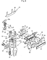
- the neutral position holding mechanism 50 that holds the yarn feeding port 12 at the low neutral position adjacent to the knitting needle 5 while keeping the selection lever 32 in an upright state at the standby position is, as shown in Fig. 4 , composed of pivot portions 51 and 51 each formed through the upper end portion of the feeder case 17 and a pair of links 53 having rotating portions 52 and 52 pivoted to the pivot portions 51 and 51 so as to be enabled to swing.
- the pair of links 53 includes engagement portions 54 each having the extreme end portion engaged with each other at the center of the feeder case 17 in a horizontal direction.
- Protrusions 55 for operating the selection lever 32 into the neutral position by pushing up the upper end portion 32a of the selection lever 32 from the lower side are formed at the respective side surfaces that face with each other.
- Operation pieces 56 each extending to the left and the right from the rotating portions 52 are formed at the upper portion of the respective links 53.
- the operation pieces 56 swung by the entraining pins 14 are formed to extend to the left and the right from the rotating portions 52, and have the upper surface oblique to be lower as it becomes closer to the engagement portion 54, and the outer end oblique downward.
- a reference numeral 57 denotes a plate of preventing dropout of the link 53. In this manner, the pair of links 53 simultaneously push up the upper end portion 32a of the selection lever 32 with the left and right protrusions 55 such that the selection lever 32 is reliably brought into the neutral position.
- the push-down member 13 that pushes down the feeder rod 20 is composed of a coupling plate 42 having one end coupled with the entraining pin 14 at an intermediate height position thereof, and a cam plate 43 having upper end portion coupled with another end of the coupling plate 42, whereby the cam plate 43 can be swung back and forth about a swing pivot pin 44 interlocking with up and down movement of the entraining pin 14.
- the entraining pin 14 is disposed on the middle of the cam plate 43 aside of the knitting yarn guide rail 11.
- a reference numeral 46 shown in Fig. 4 denotes a brake unit formed of a magnet attracted to the knitting yarn guide rail. Since the yarn feeder 9 is reduced in size and weight, the yarn feeder 9 can be stopped at an accurate position even by a light sliding friction generated by an attracting force of the magnet. Accordingly, unlike the generally employed yarn feeder, the present invention never causes the problem of unstable on stop position due to a large inertia force applied thereon, even if the yarn feeder interlocking with entraining device is stopped in a place, which fails to allow the yarn feeder to stop at the desired position. It is unnecessary to provide a special brake unit for stopping the yarn feeder at the desired position against the large inertia force.
- the knitting needles 5 disposed in parallel with each other on the needle beds 3 are advanced and retreated by the knitting cams 7.
- a solenoid is actuated responding to an output signal of pattern knitting operation so that the output shaft of the solenoid is projected downward and the entraining pin 14 of the entraining device 10 is moved upward against tension of a spring 16 through the transmission rod 15 thereafter.
- the cam plate 43 of the push-down member 13 is lifted up about a swing pivot pin 44 (refer to the cam plate 43 at the right side in Fig. 2 ).
- the solenoid is actuated in response to the signal output from the controller in front of a position where the carriage 6 confronts a predetermined yarn feeder 9 for supplying yarn to the knitting needles 5, and when the output shaft of the solenoid is receded upward, the entraining pin 14 moved upward is pushed downward by the tension of the spring 16.
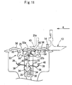
- the cam plate 43 pushes down the upper end portion (push-down portion) 25a of the upper plate 25 against a force caused by contraction of a coil spring 27, the switching roller 30 borne in the regulation hole 31 being guided downward to be centered in the lower portion of the regulation hole 31 and put on the descended position as shown in Fig. 9 and Fig.12 from the state as shown in Fig. 8 and Fig. 11 .
- the feeder rod guide 21 stands upright at the center of the feeder case 17 while projecting the yarn feeding port 12 of the feeder rod 20 downward from a lower end of the feeder rod guide 21, and the yarn feeding port 12 is located at a yarn feed position adjacent to the knitting needles 5 on a needle bed 3.
- the selection lever 32 is swung counterclockwise about the pivot portion 32b acting as a center of rotation as shown in Fig. 10 .
- the position of the selection lever 32 is held because the left gripping portion 38, which forms a holding member 36, of the elastic portion 37 of the selection lever 32 is disengaged from the engaging projection 40, and because the right gripping portion 39 is engaged with engaging projection 41.
- the yarn feeder 9 is brought by the carriage 6, and yarn is fed to the knitting needles 5 from the yarn feeding port 12 of the yarn feeder 9. In this manner, the knitting operation is performed with the yarn fed from the yarn feeder 9 in the right knitting region.
- the solenoid When knitting operation of the determined knitting region having been finished and reached to the standby position outside the knitting region, the solenoid is energized in response to a signal output from the controller, in which the output shaft of the solenoid projects downward, the entraining pin 14 expanded downward being pushed up against the force caused by stretch of the spring 16.
- the cam plate 43 of the push-down member 13 As the entraining pin 14 is moved upward, the cam plate 43 of the push-down member 13 is swung to be lifted up about the swing pivot pin 44 in the state shown by the right side of Fig. 2 .
- the feeder rod 20 that has been pushed down is pushed upward by the force caused by extension of the coil spring 27 into a position where the yarn feeding port 12 at a lower end thereof does not interfere with the yarn feeding port 12 of another yarn feeder 9, knitting needles 5, sinkers or the like.
- the position of the yarn feeder 9 in the standby state is defined by the selection lever 32.
- the gate arm (slide drive mechanism) 8 drives the carriage 6 leftward as shown by the arrow A in the drawing.
- the cam plate 43 pushes down the upper end 25a of the upper plate 25, the feeder rod 20 is moved downward.
- the switching operation with respect to the selection lever 32 may be freely done (refer to Fig. 10 ).
- the entraining pin 14 pushes the right operation member 56 in the state where the cam plate 43 keeps pushing the upper plate 25, and further the right side of the upper end 32a of the selection lever 32.
- the left side of the upper end 32a of the selection lever 32 is pushed to engage the engaging portion 19 of the left swinging piece 18 with the entraining pin 14 to bring the yarn feeder 9 into a yarn feeding state.
- the upper plate 25 has been kept pushed by the cam plate 43.
- the entraining pin 14 is disengaged from the cam plate 43 for releasing the bringing state of the yarn feeder 9, the yarn feeding is stopped by the brake unit 46.
- the selection lever 32 is kept oblique counterclockwise, the feeder rod 20 moves upward to swing to the right as shown in Fig. 10 .
- the entraining pin 14 is disengaged from the cam plate 43 so as to allow passage of the carriage 6.
- the feeder rod 20 is kept swung to the right.
- the entraining pin 14 and the cam plate 43 are activated to push the right operation member 56 with the entraining pin 14 such that the selection lever 32 is brought into the neutral position, and the engagement between the entraining pin 14 and the cam plate 43 is released when the carriage 6 turns reversely to reach the yarn feeder 9, the yarn feeding port 12 is held at the low neutral position as the resultant position is held by the gripping portions 39, and accordingly, the feeder rod 20 that moves upward is received by the roller receiving portion 35 in the state where the selection roller 30 at the upper end portion is in the neutral position.
- the pair of links 53 coupled with each other are employed.
- the invention is not limited to the structure as described above. It may be structured to push up the upper end 32a of the selection lever 32 from the lower side.
- the yarn feeder 9 is structured to swing at the standby position for knitting the fabric with the intarsia pattern.
- the swing regulation unit designated by the reference numeral 61 in Fig. 4 can be employed.
- the upper plate 25 is pushed down to the position that is not influenced by the cam plate 43, that is, the feeding position, and the protrusion 61a of the swing regulation unit 61 is inserted into the lower end of the slide slot 23a formed through the intermediate plate 23.
- the yarn feeding rod guide 21 is constrained from its sides to regulate the swinging motion to form the yarn feeder for the normal knitting.
Landscapes
- Engineering & Computer Science (AREA)
- Textile Engineering (AREA)
- Knitting Machines (AREA)
Applications Claiming Priority (2)
| Application Number | Priority Date | Filing Date | Title |
|---|---|---|---|
| JP2004200780A JP4125268B2 (ja) | 2004-07-07 | 2004-07-07 | 横編機における給糸装置のヤーンフィーダ |
| PCT/JP2005/010852 WO2006006336A1 (ja) | 2004-07-07 | 2005-06-14 | 横編機における給糸装置のヤーンフィーダ |
Publications (3)
| Publication Number | Publication Date |
|---|---|
| EP1764432A1 EP1764432A1 (en) | 2007-03-21 |
| EP1764432A4 EP1764432A4 (en) | 2009-12-02 |
| EP1764432B1 true EP1764432B1 (en) | 2013-09-04 |
Family
ID=35783691
Family Applications (1)
| Application Number | Title | Priority Date | Filing Date |
|---|---|---|---|
| EP05751163.6A Expired - Lifetime EP1764432B1 (en) | 2004-07-07 | 2005-06-14 | Yarn feeder of yarn feeding device in weft knitting machine |
Country Status (6)
| Country | Link |
|---|---|
| US (1) | US7353668B2 (enExample) |
| EP (1) | EP1764432B1 (enExample) |
| JP (1) | JP4125268B2 (enExample) |
| KR (1) | KR101170352B1 (enExample) |
| CN (1) | CN101018901B (enExample) |
| WO (1) | WO2006006336A1 (enExample) |
Families Citing this family (16)
| Publication number | Priority date | Publication date | Assignee | Title |
|---|---|---|---|---|
| JP4125267B2 (ja) * | 2004-07-07 | 2008-07-30 | 株式会社島精機製作所 | 横編機における給糸装置のヤーンフィーダ |
| CN101235574B (zh) * | 2008-03-07 | 2010-06-02 | 冯加林 | 嵌花梭箱的纱嘴换向控制机构 |
| CN102400274A (zh) * | 2010-09-14 | 2012-04-04 | 吴江华利针纺有限公司 | 引线装置 |
| US10172422B2 (en) | 2011-03-15 | 2019-01-08 | Nike, Inc. | Knitted footwear component with an inlaid ankle strand |
| US8839532B2 (en) | 2011-03-15 | 2014-09-23 | Nike, Inc. | Article of footwear incorporating a knitted component |
| US8522577B2 (en) * | 2011-03-15 | 2013-09-03 | Nike, Inc. | Combination feeder for a knitting machine |
| US9060570B2 (en) | 2011-03-15 | 2015-06-23 | Nike, Inc. | Method of manufacturing a knitted component |
| US8387418B1 (en) * | 2011-09-19 | 2013-03-05 | Pai Lung Machinery Mill Co., Ltd. | Yarn feeder for flat knitting machines |
| KR101226417B1 (ko) * | 2011-09-21 | 2013-01-24 | 파이룽 머시너리 밀 코., 엘티디. | 횡편기용 실 공급기 |
| US9404206B2 (en) * | 2013-02-28 | 2016-08-02 | Nike, Inc. | Feeder for knitting machine having pushing member |
| US9371603B2 (en) * | 2013-02-28 | 2016-06-21 | Nike, Inc. | Feeder for knitting machine with friction reducing features |
| JP6257322B2 (ja) * | 2013-12-27 | 2018-01-10 | 株式会社島精機製作所 | 横編機の給糸装置 |
| TWI851589B (zh) | 2018-07-31 | 2024-08-11 | 德商拜耳廠股份有限公司 | 編碼改良之轉胺酶蛋白質之核酸 |
| TWD208197S (zh) * | 2019-06-18 | 2020-11-11 | 義大利商聖東尼股份公司 | 紡織機構件 |
| TWD208383S (zh) * | 2019-06-18 | 2020-11-21 | 義大利商聖東尼股份公司 | 紡織機構件 |
| EP4019683B1 (de) * | 2020-12-23 | 2025-09-03 | KARL MAYER STOLL R&D GmbH | Flachstrickmaschine mit wirkmaschinenelementen in form mindestens eines fadenführers zur zuführung von einem oder mehreren separaten fäden |
Family Cites Families (12)
| Publication number | Priority date | Publication date | Assignee | Title |
|---|---|---|---|---|
| JPS56140139A (en) * | 1980-04-01 | 1981-11-02 | Shima Idea Center | Knitting of intercia pattern and yarn introducing apparatus |
| DE3310723C1 (de) * | 1983-03-24 | 1984-09-13 | H. Stoll Gmbh & Co, 7410 Reutlingen | Fadenfuehrer fuer Flachstrickmaschinen |
| JPS6151061A (ja) | 1984-08-21 | 1986-03-13 | Nippon Steel Chem Co Ltd | 導電性樹脂成型材料及びその製造方法 |
| USH1055H (en) | 1990-05-29 | 1992-05-05 | Atochem North America, Inc. | Thermal energy coagulation and washing of latex particles |
| JP2807848B2 (ja) * | 1991-07-11 | 1998-10-08 | 株式会社島精機製作所 | 横編機におけるヤーンフィーダの駆動装置 |
| JP3044370B2 (ja) * | 1997-08-21 | 2000-05-22 | 株式会社島精機製作所 | 横編機における糸供給装置 |
| TW561210B (en) * | 2000-02-29 | 2003-11-11 | Shima Seiki Mfg | Yarn carrier of weft knitting machine |
| EP1260625B1 (en) * | 2000-02-29 | 2008-06-18 | Shima Seiki Mfg., Ltd | Yarn carrier of weft knitting machine |
| CN101397717B (zh) * | 2001-03-29 | 2011-02-02 | 株式会社岛精机制作所 | 纬编机的导纱器及纬编机 |
| EP1418263B1 (en) * | 2001-07-24 | 2013-07-10 | Shima Seiki Mfg., Ltd | Yarn feeder of weft knitting machine and method of feeding yarn for weft knitting machine |
| CN1764751B (zh) * | 2003-02-26 | 2012-05-30 | 株式会社岛精机制作所 | 横机的导纱器 |
| JP4125212B2 (ja) * | 2003-10-10 | 2008-07-30 | 株式会社島精機製作所 | 着脱式編成用移動体および編成部材切換装置を備える横編機 |
-
2004
- 2004-07-07 JP JP2004200780A patent/JP4125268B2/ja not_active Expired - Fee Related
-
2005
- 2005-06-14 WO PCT/JP2005/010852 patent/WO2006006336A1/ja not_active Ceased
- 2005-06-14 CN CN2005800159619A patent/CN101018901B/zh not_active Expired - Fee Related
- 2005-06-14 KR KR1020067021665A patent/KR101170352B1/ko not_active Expired - Fee Related
- 2005-06-14 EP EP05751163.6A patent/EP1764432B1/en not_active Expired - Lifetime
- 2005-06-14 US US11/630,517 patent/US7353668B2/en not_active Expired - Fee Related
Also Published As
| Publication number | Publication date |
|---|---|
| CN101018901A (zh) | 2007-08-15 |
| WO2006006336A1 (ja) | 2006-01-19 |
| EP1764432A4 (en) | 2009-12-02 |
| JP4125268B2 (ja) | 2008-07-30 |
| EP1764432A1 (en) | 2007-03-21 |
| KR20070031291A (ko) | 2007-03-19 |
| US20080022727A1 (en) | 2008-01-31 |
| KR101170352B1 (ko) | 2012-09-07 |
| CN101018901B (zh) | 2011-02-09 |
| JP2006022426A (ja) | 2006-01-26 |
| US7353668B2 (en) | 2008-04-08 |
Similar Documents
| Publication | Publication Date | Title |
|---|---|---|
| EP1764432B1 (en) | Yarn feeder of yarn feeding device in weft knitting machine | |
| US7543462B2 (en) | Yarn feeder of yarn feeding device for weft knitting machine | |
| US6981393B2 (en) | Yarn feeders of flat knitting machine | |
| US7207194B2 (en) | Weft knitting machine with movable yarn guide member | |
| US6021651A (en) | Flat knitting machine having a yarn feeding system | |
| JP2807848B2 (ja) | 横編機におけるヤーンフィーダの駆動装置 | |
| KR100905251B1 (ko) | 횡편기의 급사장치 및 횡편기의 급사방법 | |
| JP2006022425A5 (enExample) | ||
| JP2006022426A5 (enExample) |
Legal Events
| Date | Code | Title | Description |
|---|---|---|---|
| PUAI | Public reference made under article 153(3) epc to a published international application that has entered the european phase |
Free format text: ORIGINAL CODE: 0009012 |
|
| 17P | Request for examination filed |
Effective date: 20070108 |
|
| AK | Designated contracting states |
Kind code of ref document: A1 Designated state(s): DE ES FR GB IT |
|
| DAX | Request for extension of the european patent (deleted) | ||
| RBV | Designated contracting states (corrected) |
Designated state(s): DE ES FR GB IT |
|
| A4 | Supplementary search report drawn up and despatched |
Effective date: 20091030 |
|
| GRAP | Despatch of communication of intention to grant a patent |
Free format text: ORIGINAL CODE: EPIDOSNIGR1 |
|
| GRAS | Grant fee paid |
Free format text: ORIGINAL CODE: EPIDOSNIGR3 |
|
| GRAA | (expected) grant |
Free format text: ORIGINAL CODE: 0009210 |
|
| AK | Designated contracting states |
Kind code of ref document: B1 Designated state(s): DE ES FR GB IT |
|
| REG | Reference to a national code |
Ref country code: GB Ref legal event code: FG4D |
|
| REG | Reference to a national code |
Ref country code: DE Ref legal event code: R096 Ref document number: 602005041122 Country of ref document: DE Effective date: 20131031 |
|
| PG25 | Lapsed in a contracting state [announced via postgrant information from national office to epo] |
Ref country code: ES Free format text: LAPSE BECAUSE OF FAILURE TO SUBMIT A TRANSLATION OF THE DESCRIPTION OR TO PAY THE FEE WITHIN THE PRESCRIBED TIME-LIMIT Effective date: 20130904 |
|
| REG | Reference to a national code |
Ref country code: DE Ref legal event code: R097 Ref document number: 602005041122 Country of ref document: DE |
|
| PLBE | No opposition filed within time limit |
Free format text: ORIGINAL CODE: 0009261 |
|
| STAA | Information on the status of an ep patent application or granted ep patent |
Free format text: STATUS: NO OPPOSITION FILED WITHIN TIME LIMIT |
|
| 26N | No opposition filed |
Effective date: 20140605 |
|
| REG | Reference to a national code |
Ref country code: DE Ref legal event code: R097 Ref document number: 602005041122 Country of ref document: DE Effective date: 20140605 |
|
| GBPC | Gb: european patent ceased through non-payment of renewal fee |
Effective date: 20140614 |
|
| REG | Reference to a national code |
Ref country code: FR Ref legal event code: ST Effective date: 20150227 |
|
| PG25 | Lapsed in a contracting state [announced via postgrant information from national office to epo] |
Ref country code: GB Free format text: LAPSE BECAUSE OF NON-PAYMENT OF DUE FEES Effective date: 20140614 Ref country code: FR Free format text: LAPSE BECAUSE OF NON-PAYMENT OF DUE FEES Effective date: 20140630 |
|
| PGFP | Annual fee paid to national office [announced via postgrant information from national office to epo] |
Ref country code: IT Payment date: 20220510 Year of fee payment: 18 Ref country code: DE Payment date: 20220420 Year of fee payment: 18 |
|
| REG | Reference to a national code |
Ref country code: DE Ref legal event code: R119 Ref document number: 602005041122 Country of ref document: DE |
|
| PG25 | Lapsed in a contracting state [announced via postgrant information from national office to epo] |
Ref country code: DE Free format text: LAPSE BECAUSE OF NON-PAYMENT OF DUE FEES Effective date: 20240103 |
|
| PG25 | Lapsed in a contracting state [announced via postgrant information from national office to epo] |
Ref country code: IT Free format text: LAPSE BECAUSE OF NON-PAYMENT OF DUE FEES Effective date: 20230614 |