EP1762420A2 - Navigationseinrichtung - Google Patents
Navigationseinrichtung Download PDFInfo
- Publication number
- EP1762420A2 EP1762420A2 EP06018824A EP06018824A EP1762420A2 EP 1762420 A2 EP1762420 A2 EP 1762420A2 EP 06018824 A EP06018824 A EP 06018824A EP 06018824 A EP06018824 A EP 06018824A EP 1762420 A2 EP1762420 A2 EP 1762420A2
- Authority
- EP
- European Patent Office
- Prior art keywords
- navigation device
- foot part
- housing
- navigation
- foot
- Prior art date
- Legal status (The legal status is an assumption and is not a legal conclusion. Google has not performed a legal analysis and makes no representation as to the accuracy of the status listed.)
- Withdrawn
Links
Images


Classifications
-
- G—PHYSICS
- G01—MEASURING; TESTING
- G01C—MEASURING DISTANCES, LEVELS OR BEARINGS; SURVEYING; NAVIGATION; GYROSCOPIC INSTRUMENTS; PHOTOGRAMMETRY OR VIDEOGRAMMETRY
- G01C21/00—Navigation; Navigational instruments not provided for in groups G01C1/00 - G01C19/00
- G01C21/26—Navigation; Navigational instruments not provided for in groups G01C1/00 - G01C19/00 specially adapted for navigation in a road network
-
- B—PERFORMING OPERATIONS; TRANSPORTING
- B60—VEHICLES IN GENERAL
- B60K—ARRANGEMENT OR MOUNTING OF PROPULSION UNITS OR OF TRANSMISSIONS IN VEHICLES; ARRANGEMENT OR MOUNTING OF PLURAL DIVERSE PRIME-MOVERS IN VEHICLES; AUXILIARY DRIVES FOR VEHICLES; INSTRUMENTATION OR DASHBOARDS FOR VEHICLES; ARRANGEMENTS IN CONNECTION WITH COOLING, AIR INTAKE, GAS EXHAUST OR FUEL SUPPLY OF PROPULSION UNITS IN VEHICLES
- B60K35/00—Instruments specially adapted for vehicles; Arrangement of instruments in or on vehicles
- B60K35/20—Output arrangements, i.e. from vehicle to user, associated with vehicle functions or specially adapted therefor
-
- B—PERFORMING OPERATIONS; TRANSPORTING
- B60—VEHICLES IN GENERAL
- B60K—ARRANGEMENT OR MOUNTING OF PROPULSION UNITS OR OF TRANSMISSIONS IN VEHICLES; ARRANGEMENT OR MOUNTING OF PLURAL DIVERSE PRIME-MOVERS IN VEHICLES; AUXILIARY DRIVES FOR VEHICLES; INSTRUMENTATION OR DASHBOARDS FOR VEHICLES; ARRANGEMENTS IN CONNECTION WITH COOLING, AIR INTAKE, GAS EXHAUST OR FUEL SUPPLY OF PROPULSION UNITS IN VEHICLES
- B60K35/00—Instruments specially adapted for vehicles; Arrangement of instruments in or on vehicles
- B60K35/50—Instruments characterised by their means of attachment to or integration in the vehicle
-
- B—PERFORMING OPERATIONS; TRANSPORTING
- B60—VEHICLES IN GENERAL
- B60R—VEHICLES, VEHICLE FITTINGS, OR VEHICLE PARTS, NOT OTHERWISE PROVIDED FOR
- B60R11/00—Arrangements for holding or mounting articles, not otherwise provided for
- B60R11/02—Arrangements for holding or mounting articles, not otherwise provided for for radio sets, television sets, telephones, or the like; Arrangement of controls thereof
- B60R11/0258—Arrangements for holding or mounting articles, not otherwise provided for for radio sets, television sets, telephones, or the like; Arrangement of controls thereof for navigation systems
-
- B—PERFORMING OPERATIONS; TRANSPORTING
- B60—VEHICLES IN GENERAL
- B60K—ARRANGEMENT OR MOUNTING OF PROPULSION UNITS OR OF TRANSMISSIONS IN VEHICLES; ARRANGEMENT OR MOUNTING OF PLURAL DIVERSE PRIME-MOVERS IN VEHICLES; AUXILIARY DRIVES FOR VEHICLES; INSTRUMENTATION OR DASHBOARDS FOR VEHICLES; ARRANGEMENTS IN CONNECTION WITH COOLING, AIR INTAKE, GAS EXHAUST OR FUEL SUPPLY OF PROPULSION UNITS IN VEHICLES
- B60K35/00—Instruments specially adapted for vehicles; Arrangement of instruments in or on vehicles
- B60K35/10—Input arrangements, i.e. from user to vehicle, associated with vehicle functions or specially adapted therefor
-
- H—ELECTRICITY
- H04—ELECTRIC COMMUNICATION TECHNIQUE
- H04M—TELEPHONIC COMMUNICATION
- H04M1/00—Substation equipment, e.g. for use by subscribers
- H04M1/60—Substation equipment, e.g. for use by subscribers including speech amplifiers
- H04M1/6033—Substation equipment, e.g. for use by subscribers including speech amplifiers for providing handsfree use or a loudspeaker mode in telephone sets
- H04M1/6041—Portable telephones adapted for handsfree use
- H04M1/6075—Portable telephones adapted for handsfree use adapted for handsfree use in a vehicle
-
- H—ELECTRICITY
- H04—ELECTRIC COMMUNICATION TECHNIQUE
- H04M—TELEPHONIC COMMUNICATION
- H04M2250/00—Details of telephonic subscriber devices
- H04M2250/02—Details of telephonic subscriber devices including a Bluetooth® interface
Definitions
- the invention relates to a navigation device with a navigation device for evaluating satellite navigation data, input of a navigation destination and output of a route to the navigation destination, having a housing having a display, which is releasably attachable to a footboard.
- Such navigation devices are known and are used primarily for navigation in a motor vehicle. In particular for theft prevention, it is known to releasably secure the navigation device on a foot, so that it can be taken without problems when the vehicle is left.
- the detachable connection is also advantageous if the navigation device, for example, for loading a new digital map to be connected to a data processing device.
- the known navigation devices of this type are connected via electrical contacts with the foot part, since the foot part in turn establishes the connection with a hands-free system of the motor vehicle, so that a voice output of the navigation device can be made via the speakers located in the motor vehicle.
- a vehicle antenna receiving antenna for the satellite data for example, GPS antenna; GPS gobal Positioning System.
- a disadvantage of these arrangements is a relatively high cost of the foot.
- the present invention is therefore the object of the navigation device of the type mentioned in such a way that it can be created with little effort and handle advantageous.
- a navigation device according to the invention of the type mentioned above is characterized in that the foot part has a base part, on the upper side of a circular arc portion forming the first guide member for receiving a corresponding circular arc-shaped second guide member of the housing is arranged and that the housing in the by the Guide elements formed guide in several angular positions with a latching arrangement is resiliently latched.
- the navigation device according to the invention allows the extremely simple design of the foot, yet the angular adjustment of the housing of the navigation device relative to the foot part is possible, which is essential in particular in a motor vehicle due to the different seat size of different drivers.
- the angular adjustment of the housing of the navigation device relative to the foot part is possible, which is essential in particular in a motor vehicle due to the different seat size of different drivers.
- In contrast to known solutions is dispensed with expensive ball joints o. ⁇ .
- the base part of the foot part can preferably be flexible, so that the foot part can adapt to curvatures of the upper side of the dashboard in order to be glued or detachably fastened there, for example, with Velcro fasteners.
- the base part may also be plate-shaped, in order to enable a relatively large-area attachment with its underside, which may be formed as an adhesive surface or as part of a Velcro connection.
- the base part can also be fastened in the manner of a suction cup, for example on a window pane of a vehicle.
- the guide elements can be formed in a simple manner by laterally open grooves and grooves engaging in the webs, wherein, for example, the foot part can be provided with the webs and the housing with the grooves.
- the housing may have a corresponding approach.
- a spring element between two grooves or two webs is arranged, which may be located on the spring element projections, which can engage for locking in a plurality of corresponding recesses of the counterpart. If the spring element, in a preferred embodiment, is located on the foot part, the housing will thus have the recesses on a circular arc path, into which the projections of the spring element can engage for latching in a plurality of angular positions.
- the spring element can be movable in a manner known per se by means of a protruding end in a Entarretismescardi, wherein the protruding end preferably protrudes to the rear side of the housing, so as not to disturb the aesthetic impression of the navigation device. Nevertheless, the unlocking and thus the removal of the navigation device can be made in a simple manner.
- the foot part has no electrical function for the navigation device, so that the navigation device is designed to be self-sufficient usable by the foot part.
- a complex contact arrangement between the foot and the navigation device is not required.
- TMC Traffic Message Channel
- a complex contact arrangement of the previous navigation devices is not required.
- the navigation device is thus equipped with its own satellite antenna and preferably also has its own power supply in the form of a rechargeable battery.
- the charging of the accumulator can conveniently be done with a charging cable, which is connected on the one hand to the navigation device and on the other hand to a cigarette lighter terminal of the motor vehicle.
- the guide element on the foot part is preferably designed as a separate component, which is preferably rotatably mounted in the base part of the foot part. This makes it possible not only to adjust the angular position of the housing, a substantially horizontal axis, but also to make a rotation about a substantially vertical axis. As a result, the adjustability is achieved for which previously a complex ball and socket assembly was required.
- Figure 1 shows a foot part 1, which consists of a plate-shaped base part 2 of a flexible, preferably rubber-like material.
- the base part 2 is formed centrally with an elevation on which an inclined mounting surface 3 is located.
- a separate component 4 is fixed, which has a substantially rectangular plan and is provided on two opposite longer sides, each with a wall 5, from which a horizontal web 6 projects so that the two webs 6 facing each other and are arranged at a distance from the bottom 7 of the component 4.
- a spring element 8 is centrally arranged, which is connected to a rivet 9 o. The like. With the component 4 and the base part 2. The spring element 8 protrudes beyond the component 4 and is shaped so that it can be pressed down by pressure on the free, projecting over the component 4 end 10.
- the spring element 8 has approximately centrally on its upper side two juxtaposed projections 11 as latching cams.
- a navigation device 12 can be placed, which is housed in a housing 13 and on its front side has a large-area display 14.
- the housing 13 can be seen on a side wall a slot 15 for receiving a memory card on which in particular one or more digital cards are stored.
- control buttons 16 are arranged on the front side, of which a button 16a for switching the navigation device 12 on and off, a middle button 16b as a cursor control button and a button 16c as a cancel button (ESC).
- a button 16a for switching the navigation device 12 on and off a button 16a for switching the navigation device 12 on and off
- a middle button 16b as a cursor control button
- a button 16c as a cancel button (ESC).
- Figure 1 illustrates with an arrow 1 that by pressing on the rear end 10 of the spring element 8, the housing 13 is entarretierbar of the foot part 1 and then removed by pivoting from the guide formed by the webs 6.
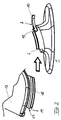
- the webs 6 and the bottom 7 of the component 4 are curved upwards as a circular arc section and cooperate with a corresponding, circular arc segment-shaped projection 17 on the underside of the housing 13 together, as Figure 2 illustrates.
- a side-open groove 18 is formed, in which the associated web 6 of the foot part can engage to be displaced in the groove 18 on the circular arc portion.
- the groove 18 is closed to the front of the housing 13 through an end wall 19 so that the pivotal movement of the housing 13 is limited to the bottom to the rear and the removal of the navigation device 12 from the foot part only by pivoting the lower part of the housing 13 forward is possible , as indicated by the arrow 2 in Figure 1.
- the installation of the navigation device 12 on the foot part is carried out by pushing or turning up the projection 17 on the guide formed by the webs 6, as is illustrated by the arrow in Figure 2.
- Figure 3 illustrates that the component 4 may be rotatably mounted on the base part 2 of the foot part 1.
- four arcuate-shaped slots 20 are arranged in the receiving surface 3, which can be attacked by corresponding hook-shaped projections 21 on the underside of the component 4, the length of the slots 20 defines the possible angle of rotation of the navigation device 12 on the foot part 1.
- the rotation is performed by a central pin 22, which rises centrally from the receiving surface 3 and engages in a corresponding (not shown) receiving opening of the component 4.
- the required snapping of the hook-shaped projections 21 into the slots 20 is possible in that the material of the base part 2 is flexible and thereby allows the passage of the angled ends of the hook-shaped projections 21 through the slot.
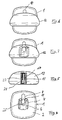
- FIG. 4 shows a top view of a foot part 1 which, in one variant, has a substantially quadrangular base surface with rounded side edges.
- Figure 5 shows the cooperating with the foot part underside of the housing 13, on which the projection 17 is arranged centrally and directed from the rear.
- the laterally open grooves 18 are formed in the laterally inwardly angled webs 6 can engage.
- Centered between the grooves 18 are each paired recesses 23, wherein in the longitudinal direction of the projection 17 a plurality of pairs of recesses 23 are arranged.
- the recesses 23 have a size and a distance from each other that they can receive the projections 11 of the spring element 8. It can be seen that the angular position of the housing 13 relative to the foot part 1 is changed by the fact that the projections 11 engage in other recesses 23.
- the shoulder 17 may have a longitudinal contact track 24 extending over the length, on which a resilient contact pin 25, which may be formed by the bolt 22 or guided in the bolt 22, abuts, when the housing 13 is mounted on the foot part 1 via the guide elements, wherein the contact between the contact pin 25 and the contact track 24 is maintained regardless of the set angular position.
- a (not shown) TMC antenna for example in the form of a wound into a flat spiral wire is inserted, for example, is injected.
- Figure 6 illustrates the top view of the navigation device 12, which is mounted on the foot part 1. It can be seen that only the rear end 10 of the spring element 8 projects beyond the contour of the navigation device 12 in order to enable unlocking of the projections 11 from the recesses 23, as a result of which the navigation device 12 can be removed from the foot part 1.
- FIG. 7 shows the plan view according to FIG. 6 with the arrangement of the foot part 1 already shown in FIG. 4 for guiding and locking the navigation device 12.
- the foot part 1 is extremely simple and inexpensive. This allows an advantageous use of the navigation device in that to a navigation device 12, several foot parts 1 are taken into use, which are mounted in several vehicles or other locations. The user of the navigation device 12 is then able to carry the navigation device 12 with him and easily and quickly in one of several vehicles, at his workplace o. The like. To attach to an existing there foot part 1. For this application, it is particularly useful that the navigation device 12 is independent of the foot part 1 is functional, so its own satellite receiving antenna, and possibly has its own speaker.
- the navigation device 12 can also be configured as a mobile phone that works with its own SIM card, with a secondary card of another mobile phone or with access data transmitted via a wireless data transmission device (eg according to the Bluetooth standard) to the navigation device (mobile phone) have been.
- a wireless data transmission device eg according to the Bluetooth standard
- the navigation device / mobile phone must be equipped with a corresponding wireless transmitting / receiving device and configured to receive the access data (in particular according to the rSAP standard).
- the navigation device 12 may be configured such that it does not process TMC signals about current traffic disruptions. However, if the navigation device 12 is set up to process such TMC signals, the navigation device 12 itself may be equipped with a TMC antenna. Preferably, however, the TMC antenna, as described, arranged in the foot part 1, so that the TMC signals via the contact pin 25 and the contact track 24 get into the navigation device 12 and placed there for display and possibly taken into account for route calculation.
Landscapes
- Engineering & Computer Science (AREA)
- Radar, Positioning & Navigation (AREA)
- Remote Sensing (AREA)
- Mechanical Engineering (AREA)
- Chemical & Material Sciences (AREA)
- Combustion & Propulsion (AREA)
- Transportation (AREA)
- Automation & Control Theory (AREA)
- Physics & Mathematics (AREA)
- General Physics & Mathematics (AREA)
- Navigation (AREA)
- Position Fixing By Use Of Radio Waves (AREA)
Abstract
Description
- Die Erfindung betrifft eine Navigationseinrichtung mit einem Navigationsgerät zur Auswertung von Satelliten-Navigationsdaten, Eingabe eines Navigationsziels und Ausgabe einer Route zum Navigationsziel, mit einem ein Display aufweisenden Gehäuse, das auf einem Fußteil lösbar befestigbar ist.
- Derartige Navigationseinrichtungen sind bekannt und werden vornehmlich zur Navigation in einem Kraftfahrzeug verwendet. Insbesondere zur Diebstahlsicherung ist es bekannt, das Navigationsgerät auf einem Fußteil lösbar zu befestigen, sodass es unproblematisch mitgenommen werden kann, wenn das Kraftfahrzeug verlassen wird. Die lösbare Verbindung ist auch dann von Vorteil, wenn das Navigationsgerät, beispielsweise zum Aufspielen einer neuen digitalen Karte, mit einem Datenverarbeitungsgerät verbunden werden soll. Die bekannten Navigationsgeräte dieser Art sind über elektrische Kontakte mit dem Fußteil verbunden, da das Fußteil seinerseits die Verbindung mit einer Freisprechanlage des Kraftfahrzeugs herstellt, sodass eine Sprachausgabe des Navigationsgeräts über die im Kraftfahrzeug befindlichen Lautsprecher erfolgen kann. Ferner ist es möglich, eine am Kraftfahrzeug angebrachte Empfangsantenne für die Satellitendaten (beispielsweise GPS-Antenne; GPS-Gobal Positioning System) zu verbinden. Nachteilig an diesen Anordnungen ist ein vergleichsweise hoher Aufwand für das Fußteil.
- Der vorliegenden Erfindung liegt daher die Aufgabe zugrunde, die Navigationseinrichtung der eingangs erwähnten Art so auszubilden, dass sie sich mit wenig Aufwand erstellen und vorteilhaft handhaben lässt.
- Zur Lösung dieser Aufgabe ist erfindungsgemäß eine Navigationseinrichtung der eingangs erwähnten Art dadurch gekennzeichnet, dass das Fußteil ein Basisteil aufweist, auf dessen Oberseite ein einen Kreisbogenabschnitt bildendes erstes Führungselement zur Aufnahme eines entsprechenden kreisbogenförmigen zweiten Führungselements des Gehäuses angeordnet ist und dass das Gehäuse in der durch die Führungselemente gebildeten Führung in mehreren Winkelstellungen mit einer Rastanordnung federnd verrastbar ist.
- Die erfindungsgemäße Navigationseinrichtung erlaubt die außerordentlich einfache Ausbildung des Fußteils, wobei dennoch die Winkeleinstellung des Gehäuses des Navigationsgeräts relativ zum Fußteil möglich ist, was insbesondere in einem Kraftfahrzeug aufgrund der unterschiedlichen Sitzgröße verschiedener Fahrer wesentlich ist. Im Unterschied zu bekannten Lösungen wird auf aufwändige Kugelgelenke o. ä. verzichtet.
- Das Basisteil des Fußteils kann vorzugsweise flexibel ausgebildet sein, sodass sich das Fußteil an Krümmungen der Oberseite des Armaturenbretts anpassen kann, um dort verklebt oder beispielsweise mit Klettverbindungen lösbar befestigt zu werden.
- Das Basisteil kann ferner tellerförmig ausgebildet sein, um eine relativ großflächige Befestigung mit seiner Unterseite, die als Klebfläche oder als Teil einer Klettverbindung ausgebildet sein kann, zu ermöglichen. Alternativ kann das Basisteil auch nach Art eines Saugnapfes, beispielsweise an einer Fensterscheibe eines Fahrzeugs, befestigbar sein.
- Die Führungselemente können in einfacher Weise durch seitlich offene Nuten und in die Nuten eingreifende Stege gebildet sein, wobei beispielsweise das Fußteil mit den Stegen und das Gehäuse mit den Nuten versehen sein kann. Hierzu kann das Gehäuse einen entsprechenden Ansatz aufweisen.
- Für die federnde Verrastung ist zweckmäßigerweise ein Federelement zwischen zwei Nuten oder zwei Stegen angeordnet, wobei sich an dem Federelement Vorsprünge befinden können, die zur Verrastung in mehrere entsprechende Ausnehmungen des Gegenparts eingreifen können. Befindet sich das Federelement, in einer bevorzugten Ausführungsform, an dem Fußteil, wird somit das Gehäuse die Ausnehmungen auf einer Kreisbogenbahn aufweisen, in die die Vorsprünge des Federelements zur Verrastung in mehreren Winkelstellungen eingreifen können.
- Das Federelement kann in an sich bekannter Weise mittels eines abstehenden Endes in eine Entarretierungsrichtung bewegbar sein, wobei das abstehende Ende vorzugsweise zur Gehäuserückseite absteht, um den ästhetischen Eindruck der Navigationseinrichtung nicht zu stören. Dennoch kann in einfacher Weise die Entarretierung und damit die Entnahme des Navigationsgeräts vorgenommen werden.
- In einer besonders bevorzugten Ausführungsform der Erfindung hat das Fußteil keine elektrische Funktion für das Navigationsgerät, sodass das Navigationsgerät autark vom Fußteil verwendbar ausgebildet ist. Dadurch ist eine aufwändige Kontaktanordnung zwischen Fußteil und dem Navigationsgerät nicht erforderlich. Allerdings kann das Fußteil in einer Variante dieser Ausführungsform mit einer in das Basisteil eingearbeitete TMC-Antenne (TMC = Traffic Message Channel) aufweisen, da es nicht unproblematisch ist, eine derartige Antenne in wirksamer Weise in dem vergleichsweise kleinen Gehäuse des Navigationsgeräts unterzubringen. In diesem Fall kann eine leitende Verbindung von der TMC-Antenne zu dem Navigationsgerät über einen auf einer Kontaktbahn geführten Schleifkontakt erfolgen, der federbelastet auf der Kontaktbahn geführt wird, wenn die Winkelstellung des Gehäuses gegenüber dem Fußteil verändert wird. Auch in dieser Ausführungsform ist eine aufwändige Kontaktanordnung der bisherigen Navigationseinrichtungen nicht erforderlich.
- Das Navigationsgerät ist somit mit einer eigenen Satellitenantenne ausgerüstet und weist vorzugsweise auch eine eigene Stromversorgung in Form eines aufladbaren Akkumulators auf. Die Aufladung des Akkumulators kann zweckmäßigerweise mit einem Aufladekabel erfolgen, das einerseits an das Navigationsgerät und andererseits an einen Zigarettenanzünderanschluss des Kraftfahrzeugs anschließbar ist.
- Das Führungselement auf dem Fußteil ist vorzugsweise als ein separates Bauteil ausgebildet, das vorzugsweise drehbar in dem Basisteil des Fußteils gelagert ist. Dadurch ist es möglich, nicht nur die Winkelstellung des Gehäuses, eine im Wesentlichen horizontale Achse einzustellen, sondern auch eine Drehung um eine im Wesentlichen vertikale Achse vorzunehmen. Dadurch wird die Einstellbarkeit erreicht, für die bisher eine aufwändige Kugelgelenkanordnung erforderlich war.
- Die Erfindung soll im Folgenden anhand eines in der Zeichnung dargestellten Ausführungsbeispiels näher erläutert werden. Es zeigen:
- Figur 1
- eine schematische perspektivische Darstellung eines Navigationsgeräts und eines Fußteils im nicht montierten Zustand des Navigationsgeräts;
- Figur 2
- eine vergrößerte Darstellung der Führungselemente des Gehäuses des Navigationsgeräts und des Fußteils;
- Figur 3
- eine explodierte Darstellung des Fußteils mit einem separaten Bauteil, dass das Führungselement des Fußteils und ein Federelement aufweist;
- Figur 4
- eine Draufsicht auf das Fußteil;
- Figur 5
- eine Ansicht der Unterseite des Navigationsgeräts mit dem mit dem Fußteil zusammenwirkenden Ansatz;
- Figur 6
- eine Draufsicht auf das auf das Fußteil montierte Navigationsgerät;
- Figur 7
- eine Draufsicht gemäß Figur 6 mit einer Darstellung der Führungs- und Arretierungsvorrichtung des Fußteils.
- Figur 1 zeigt ein Fußteil 1, das aus einem tellerförmigen Basisteil 2 aus einem flexiblen, vorzugsweise gummiähnlichen Material besteht. Das Basisteil 2 ist mittig mit einer Erhöhung geformt, auf der sich eine schräg gestellte Montagefläche 3 befindet. Auf der Montagefläche 3 ist ein separates Bauteil 4 befestigt, das einen im Wesentlichen rechteckigen Grundriss aufweist und an zwei einander gegenüberliegenden längeren Seiten mit je einer Wand 5 versehen ist, von der ein horizontaler Steg 6 so absteht, dass die beiden Stege 6 zueinander zeigen und mit Abstand vom Boden 7 des Bauteils 4 angeordnet sind.
- Zwischen den beiden Stegen 6 ist mittig ein Federelement 8 angeordnet, das mit einem Niet 9 o. dgl. mit dem Bauteil 4 bzw. dem Basisteil 2 verbunden ist. Das Federelement 8 ragt über das Bauteil 4 hinaus und ist so geformt, dass es durch Druck auf das freie, über das Bauteil 4 ragende Ende 10 nach unten drückbar ist. Das Federelement 8 weist etwa mittig an seiner Oberseite zwei nebeneinander angeordnete Vorsprünge 11 als Rastnocken auf.
- Auf das Fußteil 1 ist ein Navigationsgerät 12 aufsetzbar, das in einem Gehäuse 13 untergebracht ist und an seiner Vorderseite ein großflächiges Display 14 aufweist. Das Gehäuse 13 lässt an einer Seitenwand einen Schlitz 15 zur Aufnahme einer Speicherkarte erkennen, auf der insbesondere eine oder mehrere digitale Karten gespeichert sind.
- Unterhalb des Displays sind auf der Vorderseite Bedientasten 16 angeordnet, von denen eine Taste 16a zum Ein- und Ausschalten des Navigationsgeräts 12, eine mittlere Taste 16b als Cursor-Steuertaste und eine Taste 16c als Abbruchtaste (ESC) ausgebildet ist.
- Figur 1 verdeutlicht mit einem Pfeil ①, dass durch Drücken auf das hintere Ende 10 des Federelements 8 das Gehäuse 13 von dem Fußteil 1 entarretierbar ist und dann durch Schwenken aus der durch die Stege 6 gebildeten Führung entnehmbar ist.
- Die Stege 6 und der Boden 7 des Bauteils 4 sind als Kreisbogenabschnitt nach oben gekrümmt und wirken mit einem entsprechenden, kreisbogenabschnittförmig geformten Ansatz 17 an der Unterseite des Gehäuses 13 zusammen, wie Figur 2 verdeutlicht. An dem Ansatz 17 ist eine zur Seite hin offene Nut 18 ausgebildet, in die der zugehörige Steg 6 des Fußteils eingreifen kann, um in der Nut 18 auf dem Kreisbogenabschnitt verschoben zu werden. Die Nut 18 ist zur Vorderseite des Gehäuses 13 hin durch eine Stirnwand 19 verschlossen, sodass die Schwenkbewegung des Gehäuses 13 mit der Unterseite nach hinten begrenzt ist und die Entnahme des Navigationsgeräts 12 vom Fußteil nur durch eine Schwenkung des Unterteils des Gehäuses 13 nach vorn möglich ist, wie dies der Pfeil ② in Figur 1 andeutet.
- Die Montage des Navigationsgeräts 12 auf dem Fußteil erfolgt durch Aufschieben bzw. Aufdrehen des Ansatzes 17 auf die durch die Stege 6 gebildeten Führung, wie dies durch den Pfeil in Figur 2 verdeutlicht ist.
- Figur 3 verdeutlicht, dass das Bauteil 4 auf dem Basisteil 2 des Fußteils 1 drehbar gelagert sein kann. Hierzu sind in der Aufnahmefläche 3 vier kreisbogenabschnittförmige Schlitze 20 angeordnet, die von entsprechenden hakenförmigen Ansätzen 21 an der Unterseite des Bauteils 4 untergriffen werden können, die Länge der Schlitze 20 definiert den möglichen Drehwinkel des Navigationsgeräts 12 auf dem Fußteil 1. Die Drehung erfolgt um einen mittigen Bolzen 22, der sich von der Aufnahmefläche 3 mittig nach oben erhebt und in eine entsprechende (nicht dargestellte) Aufnahmeöffnung des Bauteils 4 eingreift. Das erforderliche Einschnappen der hakenförmigen Ansätze 21 in die Schlitze 20 ist dadurch möglich, dass das Material des Basisteils 2 flexibel ist und dadurch den Durchtritt der abgewinkelten Enden der hakenförmigen Ansätze 21 durch den Schlitz ermöglicht.
- Figur 4 zeigt in einer Draufsicht ein Fußteil 1, das in einer Variante eine im Wesentlichen viereckige Grundfläche mit abgerundeten Seitenkanten aufweist.
- Figur 5 zeigt die mit dem Fußteil zusammenwirkende Unterseite des Gehäuses 13, auf der der Ansatz 17 mittig und von vom nach hinten gerichtet angeordnet ist. In dem Ansatz 17 sind die seitlich offenen Nuten 18 ausgebildet in die die seitlich nach innen abgewinkelten Stege 6 eingreifen können. Mittig zwischen den Nuten 18 befindet sich jeweils paarweise angeordnete Ausnehmungen 23, wobei in Längsrichtung des Ansatzes 17 mehrere Paare der Ausnehmungen 23 angeordnet sind. Die Ausnehmungen 23 weisen eine Größe und einen Abstand zueinander auf, dass sie die Vorsprünge 11 des Federelements 8 aufnehmen können. Es ist erkennbar, dass die Winkelstellung des Gehäuses 13 relativ zum Fußteil 1 dadurch veränderbar ist, dass die Vorsprünge 11 in andere Ausnehmungen 23 eingreifen.
- Zwischen den Ausnehmungen 23 kann der Absatz 17 eine sich über die Länge erstreckende mittige Kontaktbahn 24 aufweisen, auf der ein federnder Kontaktstift 25, der durch den Bolzen 22 gebildet oder in dem Bolzen 22 geführt sein kann, anliegt, wenn das Gehäuse 13 über die Führungselemente auf dem Fußteil 1 montiert ist, wobei unabhängig von der eingestellten Winkelstellung der Kontakt zwischen dem Kontaktstift 25 und der Kontaktbahn 24 erhalten bleibt. Diese Anordnung ist von Bedeutung, wenn in das Basisteil 2 des Fußteils 1 eine (nicht dargestellte) TMC-Antenne, beispielsweise in Form eines zu einer flächigen Spirale gewickelten Drahtes eingelassen ist, beispielsweise eingespritzt ist.
- Figur 6 verdeutlicht die Draufsicht auf das Navigationsgerät 12, das auf dem Fußteil 1 montiert ist. Es ist erkennbar, dass nur das hintere Ende 10 des Federelements 8 über die Kontur des Navigationsgeräts 12 hinausragt, um eine Entarretierung der Vorsprünge 11 aus den Ausnehmungen 23 zu ermöglichen, wodurch das Navigationsgerät 12 vom Fußteil 1 entnehmbar ist.
- Figur 7 zeigt die Draufsicht gemäß Figur 6 mit der bereits aus Figur 4 ersichtlichen Anordnung des Fußteils 1 zur Führung und Arretierung des Navigationsgeräts 12.
- Es ist erkennbar, dass das Fußteil 1 außerordentlich einfach und preiswert ausgebildet ist. Dies ermöglicht eine vorteilhafte Verwendung der Navigationseinrichtung dadurch, dass zu einem Navigationsgerät 12 mehrere Fußteile 1 in Benutzung genommen werden, die in mehreren Fahrzeugen oder an anderen Stellen montiert werden. Der Benutzer des Navigationsgeräts 12 ist dann in der Lage, das Navigationsgerät 12 mit sich zu führen und unkompliziert und schnell in einem von mehreren Kraftfahrzeugen, an seinem Arbeitsplatz o. dgl. an einem dort vorhandenen Fußteil 1 zu befestigen. Für diese Anwendung ist es besonders sinnvoll, dass das Navigationsgerät 12 unabhängig von dem Fußteil 1 funktionsfähig ist, also eine eigene Satelliten-Empfangsantenne, und ggf. einen eigenen Lautsprecher aufweist. Das Navigationsgerät 12 kann dabei auch als Mobiltelefon ausgebildet sein, das mit einer eigenen SIM-Karte, mit einer Zweitkarte eines anderen Mobiltelefons oder mit Zugangsdaten arbeitet, die über eine drahtlose Datenübertragungseinrichtung (z.B. nach dem Bluetooth-Standard) auf das Navigationsgerät (Mobiltelefon) übertragen worden sind. In diesem Fall muss das Navigationsgerät/Mobiltelefon mit einer entsprechenden drahtlosen Sende-/Empfangseinrichtung ausgestattet und dafür eingerichtet sein, die Zugangsdaten (insbesondere nach dem rSAP-Standard) zu empfangen.
- Das Navigationsgerät 12 kann so ausgebildet sein, dass es TMC-Signale über aktuelle Verkehrsstörungen nicht bearbeitet. Wenn das Navigationsgerät 12 jedoch zur Verarbeitung derartiger TMC-Signale eingerichtet ist, kann das Navigationsgerät 12 selbst mit einer TMC-Antenne ausgestattet sein. Vorzugsweise ist jedoch die TMC-Antenne, wie beschrieben, in dem Fußteil 1 angeordnet, sodass die TMC-Signale über den Kontaktstift 25 und die Kontaktbahn 24 in das Navigationsgerät 12 gelangen und dort zur Anzeige gebracht und ggf. zur Routenberechnung berücksichtigt werden können.
Claims (15)
- Navigationseinrichtung mit einem Navigationsgerät (12) zur Auswertung von Satelliten-Navigationsdaten, Eingabe eines Navigationsziels und Ausgabe einer Route zum Navigationsziel, mit einem ein Display (14) aufweisenden Gehäuse (13), das auf einem Fußteil (1) lösbar befestigbar ist, dadurch gekennzeichnet, dass das Fußteil (1) ein Basisteil (2) aufweist, auf dessen Oberseite ein einen Kreisbogenabschnitt bildendes erstes Führungselement (6) zur Aufnahme eines entsprechenden kreisbogenförmigen zweiten Führungselements (18) des Gehäuses (13) angeordnet ist und dass das Gehäuse (13) in der durch die Führungselemente gebildeten Führung in mehreren Winkelstellungen mit einer Rastanordnung federnd verrastbar ist.
- Navigationseinrichtung nach Anspruch 1, dadurch gekennzeichnet, dass das Material des Basisteils (2) flexibel ist.
- Navigationseinrichtung nach Anspruch 1 oder 2, dadurch gekennzeichnet, dass die Führungselemente durch paarweise in seitlich offene Nuten (18) eingreifende Stege (6) gebildet sind.
- Navigationseinrichtung nach Anspruch 3, dadurch gekennzeichnet, dass ein Federelement (8) zwischen zwei Nuten (18) oder zwei Stegen (6) angeordnet ist, an dem sich Vorsprünge (11) befinden, die zur Verrastung in mehrere entsprechende Ausnehmungen (23) eingreifen können.
- Navigationseinrichtung nach Anspruch 4, dadurch gekennzeichnet, dass das Federelement (8) mittels eines abstehenden Endes (10) in eine Entarretierungsrichtung bewegbar ist.
- Navigationseinrichtung nach Anspruch 4 oder 5, dadurch gekennzeichnet, dass das Federelement (8) an dem Fußteil (1) und die Ausnehmungen (23) an dem Gehäuse (13) angebracht sind.
- Navigationseinrichtung nach einem der Ansprüche 1 bis 6, dadurch gekennzeichnet, dass das Navigationsgerät (12) autark vom Fußteil (1) verwendbar ausgebildet it.
- Navigationseinrichtung nach einem der Ansprüche 1 bis 7, dadurch gekennzeichnet, dass das erste Führungselement (6) mit dem zugehörigen Teil der Rastanordnung drehbar im Fußteil (1) gelagert ist.
- Navigationseinrichtung nach Anspruch 8, dadurch gekennzeichnet, dass das erste Führungselement (6) auf einem separaten Bauteil (4) ausgebildet ist, das drehbar in dem Basisteil (2) des Fußteils (1) gelagert ist.
- Navigationseinrichtung nach einem der Ansprüche 1 bis 9, dadurch gekennzeichnet, dass das Basisteil (2) tellerförmig ausgebildet ist.
- Navigationseinrichtung nach einem der Ansprüche 1 bis 10, dadurch gekennzeichnet, dass die Unterseite des Basisteils (2) als Klebfläche ausgebildet ist.
- Navigationseinrichtung nach einem der Ansprüche 1 bis 10, dadurch gekennzeichnet, dass die Unterseite des Basisteils (2) mit einem Teil einer Klettverbindung versehen ist.
- Navigationseinrichtung nach einem der Ansprüche 1 bis 12, dadurch gekennzeichnet, dass das Fußteil (1) keine elektrisch wirkenden Elemente enthält.
- Navigationseinrichtung nach einem der Ansprüche 1 bis 12, dadurch gekennzeichnet, dass das Fußteil (1) eine eingearbeitete TMC-Antenne aufweist und dass eine leitende Verbindung von der TMC-Antenne zu dem Navigationsgerät (12) über einen auf einer Kontaktbahn (24) geführten Schleifkontakt (25) erfolgt.
- Navigationseinrichtung nach einem der Ansprüche 1 bis 14, bestehend aus mehreren Fußteilen (1), auf die das Navigationsgerät (12) aufsetzbar ist.
Applications Claiming Priority (1)
| Application Number | Priority Date | Filing Date | Title |
|---|---|---|---|
| DE102005043863A DE102005043863B4 (de) | 2005-09-09 | 2005-09-09 | Navigationseinrichtung |
Publications (2)
| Publication Number | Publication Date |
|---|---|
| EP1762420A2 true EP1762420A2 (de) | 2007-03-14 |
| EP1762420A3 EP1762420A3 (de) | 2008-07-30 |
Family
ID=37492370
Family Applications (1)
| Application Number | Title | Priority Date | Filing Date |
|---|---|---|---|
| EP06018824A Withdrawn EP1762420A3 (de) | 2005-09-09 | 2006-09-08 | Navigationseinrichtung |
Country Status (2)
| Country | Link |
|---|---|
| EP (1) | EP1762420A3 (de) |
| DE (2) | DE102005043863B4 (de) |
Cited By (3)
| Publication number | Priority date | Publication date | Assignee | Title |
|---|---|---|---|---|
| CN103818319A (zh) * | 2013-12-25 | 2014-05-28 | 浙江吉利控股集团有限公司 | 汽车导航仪的固定装置 |
| CN105172700A (zh) * | 2015-09-10 | 2015-12-23 | 姜超 | 一种车载导航仪装置 |
| US20160193924A1 (en) * | 2015-01-02 | 2016-07-07 | Hyundai Motor Company | Display apparatus for vehicle and vehicle having the display apparatus |
Families Citing this family (3)
| Publication number | Priority date | Publication date | Assignee | Title |
|---|---|---|---|---|
| DE102007012617A1 (de) * | 2007-03-13 | 2008-09-18 | Funkwerk Dabendorf-Gmbh | Halter für portables Navigationsgerät |
| DE102008025640B4 (de) | 2008-01-16 | 2012-04-26 | Navigon Ag | Befestigungsvorrichtung zur Befestigung eines transportablen elektronischen Geräts |
| DE102009048158A1 (de) * | 2009-10-02 | 2010-09-23 | Audi Ag | Anordnung zum Halten von elektrischen Geräten, insbesondere eines Navigationsgeräts innerhalb eines Fahrzeugs |
Family Cites Families (11)
| Publication number | Priority date | Publication date | Assignee | Title |
|---|---|---|---|---|
| DE1995786U (de) * | 1967-09-23 | 1968-10-31 | Henricus Johannes Mic Koopmans | Kugelgelenk. |
| DE19633003A1 (de) * | 1996-08-16 | 1998-02-19 | Philips Patentverwaltung | Vorrichtung zur drehbaren Lagerung von Gegenständen um eine Drehachse |
| US6089520A (en) | 1996-09-03 | 2000-07-18 | Mag Technology Co., Ltd. | Swivel base structure |
| US6129321A (en) * | 1998-11-16 | 2000-10-10 | Garmin Corporation | Mounting apparatus for an electronic device |
| DE29907472U1 (de) * | 1999-04-27 | 1999-07-22 | Fink, Christian, 80634 München | Mobiles Satellitennavigationssystem |
| CN1309839A (zh) * | 1999-05-19 | 2001-08-22 | 三星电子株式会社 | 用于卫星导航系统的便携式接收器-指示器 |
| US6480378B2 (en) * | 2001-04-06 | 2002-11-12 | Dean Chang | Multi-angle placement rack of personal digital assistant for use in an automobile |
| JP3594011B2 (ja) | 2001-11-30 | 2004-11-24 | 株式会社デンソー | ナビゲーション装置 |
| GB0405795D0 (en) | 2004-03-15 | 2004-04-21 | Tom Tom B V | Navigation device displaying travel information |
| DE202004008269U1 (de) | 2004-05-19 | 2005-09-22 | Buchhalter, Thomas | Befestigungsvorrichtung für einen mobilen Navigationsrechner sowie Navigationssystem |
| DE202005001986U1 (de) * | 2005-02-07 | 2005-04-14 | Richter, Harald | Universalgelenkanordnung zwischen einem Gerätehalter und einem Tragarm oder einer Konsole |
-
2005
- 2005-09-09 DE DE102005043863A patent/DE102005043863B4/de not_active Expired - Fee Related
- 2005-09-09 DE DE202005021680U patent/DE202005021680U1/de not_active Expired - Lifetime
-
2006
- 2006-09-08 EP EP06018824A patent/EP1762420A3/de not_active Withdrawn
Cited By (5)
| Publication number | Priority date | Publication date | Assignee | Title |
|---|---|---|---|---|
| CN103818319A (zh) * | 2013-12-25 | 2014-05-28 | 浙江吉利控股集团有限公司 | 汽车导航仪的固定装置 |
| CN103818319B (zh) * | 2013-12-25 | 2016-03-02 | 浙江吉利控股集团有限公司 | 汽车导航仪的固定装置 |
| US20160193924A1 (en) * | 2015-01-02 | 2016-07-07 | Hyundai Motor Company | Display apparatus for vehicle and vehicle having the display apparatus |
| US9731602B2 (en) * | 2015-01-02 | 2017-08-15 | Hyundai Motor Company | Display apparatus for vehicle and vehicle having the display apparatus |
| CN105172700A (zh) * | 2015-09-10 | 2015-12-23 | 姜超 | 一种车载导航仪装置 |
Also Published As
| Publication number | Publication date |
|---|---|
| DE102005043863A1 (de) | 2007-03-22 |
| DE102005043863B4 (de) | 2009-04-30 |
| DE202005021680U1 (de) | 2009-03-19 |
| EP1762420A3 (de) | 2008-07-30 |
Similar Documents
| Publication | Publication Date | Title |
|---|---|---|
| EP1080513B2 (de) | Fahrzeug-antenneneinrichtung | |
| EP0851595A2 (de) | Haltevorrichtung für eine Kommunikationseinheit | |
| EP1773625B1 (de) | Multifunktionales stecksystem | |
| DE102004062177B4 (de) | Haltevorrichtung zur Aufnahme eines Mobiltelefons | |
| DE19715545B4 (de) | Batterieaufnahmefach, Mikrofon und elektronisches Gerät | |
| DE112007000719T5 (de) | Modulares Befestigungssystem für elektronische Einrichtungen | |
| EP3475125B1 (de) | Haltersystem für ein elektronisches gerät in einem fahrzeug | |
| EP1652729A1 (de) | Modularer Gerätehalter mit Mehrzweck-Zwischenbaubox für Kleincomputer, Handys und dergleichen | |
| DE3013140A1 (de) | Vorrichtung zum verhindern des einschlafens des fahrers eines fahrzeuges | |
| DE2340283A1 (de) | Steckverbindung fuer tragbare elektronische geraete | |
| WO2019007450A1 (de) | Halterungsanordnung für mobile endgeräte | |
| DE19850044C2 (de) | Mobiltelefon-Halterung für ein Fahrzeug | |
| EP1762420A2 (de) | Navigationseinrichtung | |
| DE102005020981B4 (de) | Telefon-Freisprechanlage für ein Mobiltelefon | |
| WO2014044577A1 (de) | Stecksystem für die halterung mindestens eines gegenstandes im innenraum eines kraftfahrzeugs | |
| DE102004063982A1 (de) | Kontaktiervorrichtung für eine Chipkarte, insbesondere für eine SIM-Karte | |
| EP0822693B1 (de) | Freisprecheinrichtung für Telefone in Kraftfahrzeugen | |
| EP0634308B1 (de) | Einrichtung mit einer Halterung und einem Kabel für ein Handfunktelefon | |
| WO2008128586A1 (de) | Gerätehalter für mobile geräte | |
| DE102010049104B4 (de) | Abdeckeinrichtung für eine Sitzschiene eines Fahrzeugsitzes | |
| DE10308189A1 (de) | Haltevorrichtung für mobile Benutzereinrichtungen | |
| DE9400985U1 (de) | Adapter für ein Handfunkkommunikationsgerät | |
| DE102009009447B3 (de) | Halterung für ein mobiles elektronisches Gerät zur temporären Fixierung des Gerätes an der Halterung | |
| EP0687437B1 (de) | Papierrollenhalter | |
| DE3738389A1 (de) | Mobilfunkanlage mit halterung fuer eine hoererauflage |
Legal Events
| Date | Code | Title | Description |
|---|---|---|---|
| PUAI | Public reference made under article 153(3) epc to a published international application that has entered the european phase |
Free format text: ORIGINAL CODE: 0009012 |
|
| AK | Designated contracting states |
Kind code of ref document: A2 Designated state(s): AT BE BG CH CY CZ DE DK EE ES FI FR GB GR HU IE IS IT LI LT LU LV MC NL PL PT RO SE SI SK TR |
|
| AX | Request for extension of the european patent |
Extension state: AL BA HR MK YU |
|
| PUAL | Search report despatched |
Free format text: ORIGINAL CODE: 0009013 |
|
| AK | Designated contracting states |
Kind code of ref document: A3 Designated state(s): AT BE BG CH CY CZ DE DK EE ES FI FR GB GR HU IE IS IT LI LT LU LV MC NL PL PT RO SE SI SK TR |
|
| AX | Request for extension of the european patent |
Extension state: AL BA HR MK RS |
|
| 17P | Request for examination filed |
Effective date: 20080722 |
|
| AKX | Designation fees paid |
Designated state(s): AT BE BG CH CY CZ DE DK EE ES FI FR GB GR HU IE IS IT LI LT LU LV MC NL PL PT RO SE SI SK TR |
|
| GRAP | Despatch of communication of intention to grant a patent |
Free format text: ORIGINAL CODE: EPIDOSNIGR1 |
|
| STAA | Information on the status of an ep patent application or granted ep patent |
Free format text: STATUS: THE APPLICATION IS DEEMED TO BE WITHDRAWN |
|
| 18D | Application deemed to be withdrawn |
Effective date: 20110120 |