EP1762315A1 - Dispositif de connection par déformation plastique - Google Patents
Dispositif de connection par déformation plastique Download PDFInfo
- Publication number
- EP1762315A1 EP1762315A1 EP06120237A EP06120237A EP1762315A1 EP 1762315 A1 EP1762315 A1 EP 1762315A1 EP 06120237 A EP06120237 A EP 06120237A EP 06120237 A EP06120237 A EP 06120237A EP 1762315 A1 EP1762315 A1 EP 1762315A1
- Authority
- EP
- European Patent Office
- Prior art keywords
- tool
- tool holder
- joining
- frame
- load
- Prior art date
- Legal status (The legal status is an assumption and is not a legal conclusion. Google has not performed a legal analysis and makes no representation as to the accuracy of the status listed.)
- Granted
Links
- 230000005489 elastic deformation Effects 0.000 claims description 9
- 230000001419 dependent effect Effects 0.000 claims description 3
- 230000000750 progressive effect Effects 0.000 claims description 2
- 230000004323 axial length Effects 0.000 description 7
- 238000000034 method Methods 0.000 description 4
- 238000005452 bending Methods 0.000 description 3
- 239000000463 material Substances 0.000 description 2
- 239000002184 metal Substances 0.000 description 2
- 230000006978 adaptation Effects 0.000 description 1
- 230000006735 deficit Effects 0.000 description 1
- 238000000465 moulding Methods 0.000 description 1
- 238000005482 strain hardening Methods 0.000 description 1
- 238000005496 tempering Methods 0.000 description 1
- 230000003313 weakening effect Effects 0.000 description 1
Images


Classifications
-
- B—PERFORMING OPERATIONS; TRANSPORTING
- B30—PRESSES
- B30B—PRESSES IN GENERAL
- B30B15/00—Details of, or accessories for, presses; Auxiliary measures in connection with pressing
- B30B15/04—Frames; Guides
- B30B15/047—C-shaped frames
-
- B—PERFORMING OPERATIONS; TRANSPORTING
- B21—MECHANICAL METAL-WORKING WITHOUT ESSENTIALLY REMOVING MATERIAL; PUNCHING METAL
- B21J—FORGING; HAMMERING; PRESSING METAL; RIVETING; FORGE FURNACES
- B21J15/00—Riveting
- B21J15/10—Riveting machines
-
- Y—GENERAL TAGGING OF NEW TECHNOLOGICAL DEVELOPMENTS; GENERAL TAGGING OF CROSS-SECTIONAL TECHNOLOGIES SPANNING OVER SEVERAL SECTIONS OF THE IPC; TECHNICAL SUBJECTS COVERED BY FORMER USPC CROSS-REFERENCE ART COLLECTIONS [XRACs] AND DIGESTS
- Y10—TECHNICAL SUBJECTS COVERED BY FORMER USPC
- Y10T—TECHNICAL SUBJECTS COVERED BY FORMER US CLASSIFICATION
- Y10T29/00—Metal working
- Y10T29/49—Method of mechanical manufacture
- Y10T29/49826—Assembling or joining
- Y10T29/49833—Punching, piercing or reaming part by surface of second part
- Y10T29/49835—Punching, piercing or reaming part by surface of second part with shaping
-
- Y—GENERAL TAGGING OF NEW TECHNOLOGICAL DEVELOPMENTS; GENERAL TAGGING OF CROSS-SECTIONAL TECHNOLOGIES SPANNING OVER SEVERAL SECTIONS OF THE IPC; TECHNICAL SUBJECTS COVERED BY FORMER USPC CROSS-REFERENCE ART COLLECTIONS [XRACs] AND DIGESTS
- Y10—TECHNICAL SUBJECTS COVERED BY FORMER USPC
- Y10T—TECHNICAL SUBJECTS COVERED BY FORMER US CLASSIFICATION
- Y10T29/00—Metal working
- Y10T29/49—Method of mechanical manufacture
- Y10T29/49826—Assembling or joining
- Y10T29/49908—Joining by deforming
- Y10T29/49938—Radially expanding part in cavity, aperture, or hollow body
- Y10T29/49943—Riveting
-
- Y—GENERAL TAGGING OF NEW TECHNOLOGICAL DEVELOPMENTS; GENERAL TAGGING OF CROSS-SECTIONAL TECHNOLOGIES SPANNING OVER SEVERAL SECTIONS OF THE IPC; TECHNICAL SUBJECTS COVERED BY FORMER USPC CROSS-REFERENCE ART COLLECTIONS [XRACs] AND DIGESTS
- Y10—TECHNICAL SUBJECTS COVERED BY FORMER USPC
- Y10T—TECHNICAL SUBJECTS COVERED BY FORMER US CLASSIFICATION
- Y10T29/00—Metal working
- Y10T29/49—Method of mechanical manufacture
- Y10T29/49826—Assembling or joining
- Y10T29/49947—Assembling or joining by applying separate fastener
- Y10T29/49954—Fastener deformed after application
- Y10T29/49956—Riveting
-
- Y—GENERAL TAGGING OF NEW TECHNOLOGICAL DEVELOPMENTS; GENERAL TAGGING OF CROSS-SECTIONAL TECHNOLOGIES SPANNING OVER SEVERAL SECTIONS OF THE IPC; TECHNICAL SUBJECTS COVERED BY FORMER USPC CROSS-REFERENCE ART COLLECTIONS [XRACs] AND DIGESTS
- Y10—TECHNICAL SUBJECTS COVERED BY FORMER USPC
- Y10T—TECHNICAL SUBJECTS COVERED BY FORMER US CLASSIFICATION
- Y10T29/00—Metal working
- Y10T29/53—Means to assemble or disassemble
- Y10T29/53039—Means to assemble or disassemble with control means energized in response to activator stimulated by condition sensor
- Y10T29/53061—Responsive to work or work-related machine element
- Y10T29/53065—Responsive to work or work-related machine element with means to fasten by deformation
- Y10T29/5307—Self-piercing work part
-
- Y—GENERAL TAGGING OF NEW TECHNOLOGICAL DEVELOPMENTS; GENERAL TAGGING OF CROSS-SECTIONAL TECHNOLOGIES SPANNING OVER SEVERAL SECTIONS OF THE IPC; TECHNICAL SUBJECTS COVERED BY FORMER USPC CROSS-REFERENCE ART COLLECTIONS [XRACs] AND DIGESTS
- Y10—TECHNICAL SUBJECTS COVERED BY FORMER USPC
- Y10T—TECHNICAL SUBJECTS COVERED BY FORMER US CLASSIFICATION
- Y10T29/00—Metal working
- Y10T29/53—Means to assemble or disassemble
- Y10T29/5343—Means to drive self-piercing work part
-
- Y—GENERAL TAGGING OF NEW TECHNOLOGICAL DEVELOPMENTS; GENERAL TAGGING OF CROSS-SECTIONAL TECHNOLOGIES SPANNING OVER SEVERAL SECTIONS OF THE IPC; TECHNICAL SUBJECTS COVERED BY FORMER USPC CROSS-REFERENCE ART COLLECTIONS [XRACs] AND DIGESTS
- Y10—TECHNICAL SUBJECTS COVERED BY FORMER USPC
- Y10T—TECHNICAL SUBJECTS COVERED BY FORMER US CLASSIFICATION
- Y10T29/00—Metal working
- Y10T29/53—Means to assemble or disassemble
- Y10T29/53709—Overedge assembling means
- Y10T29/5377—Riveter
Definitions
- the invention relates to a joining device for forming-technical joining with a frame open on one side, a drive arranged on the frame with a movable punch and a tool holder, which supports a die lying opposite the punch on the frame.
- the invention further relates to such a joining device with a tool holder set comprising at least two tool holders of different lengths, which are interchangeable with each other and hold and support a tool lying opposite the punch on the frame.
- Joining devices of the specified type are primarily used for joining workpieces made of sheet metal, for example by riveting, punch riveting or clinching.
- Joining devices for example in automotive applications, there is the problem that the shape of the components to be joined requires different positions of the punch-opposed tool within the frame. Also, a change in the maximum opening width between the punch and the tool is often required for optimal adaptation of the joining device to different joining tasks.
- the angular deviations in the reasonable order of magnitude are as equal as possible and do not depend on the position of the joint within the joining device, so that this can be taken into account in the design of the joining tools and the interpretation of the joining process.
- Various angular deviations at different positions of the joint in the joining tool are considered disadvantageous.
- the stress on the joining device during joining also results in an offset of the joint relative to the frame transversely to the longitudinal axes of punch and tool. This offset leads to an additional stress on the parts to be joined and of the devices carrying the joining device, for example of a robot, and should therefore also be as small as possible in every position of the joint.
- the invention has for its object to provide a joining device of the type specified, in which the load occurring during joining angle deviation between the longitudinal axes of the punch and tool is small. Furthermore, there is the task of keeping the offset of the joint relative to the frame as small as possible.
- the tool holder is designed so that it with progressive load on Joining an elastic deformation undergoes, which at least partially compensates for the load-dependent spreading of the legs of the frame.
- the invention is based on the finding that the angle deviation occurring during the joining between the longitudinal axis of the punch and the longitudinal axis of the tool can be influenced by the deformation behavior of the tool holder under load in such a way that the tool holder bends under load in a direction that the Bending direction of the leg of the frame is opposite, without the stability and support function of the tool holder is affected.
- the invention has the advantage that can be achieved with little effort, a smaller angular deviation and thus better joining results.
- the load of the joining device by lateral forces is reduced and the service life of the joining device and the tools is improved.
- a joining device with a tool holder set comprising at least two tool holder of different length, which are interchangeable and support a tool lying opposite the punch on the frame and support, to achieve that occurring due to stress during joining angle deviation between the longitudinal axes of punch and tool from the position of the tool in the joining device is largely independent, is further provided according to the invention that the various tool holder of the tool holder set are designed so that their respective elastic deformation under the load applied during the joining one within a predetermined narrow Area, maximum angular deviation between the longitudinal axis of the punch and the longitudinal axis of the tool causes.
- the different tool holder can be adapted to the resulting from their length each load situation such that provided for each tool holder during joining, same process conditions, essentially the same maximum angular deviations result.
- the necessary Knowledge and methods to influence the deformation behavior of the tool holder in the sense of the invention are available to the person skilled in the art and can be supported by empirical measures.
- the bending tendency of a longer tool holder can be promoted by suitable weakening of its cross section to cause under load a tool holder slightly curving shape change, which partially compensates for the change in shape of the frame and thereby allows compliance with a predetermined angular deviation.
- the size of the angular deviations to be maintained with the various tool holders will be selected so that the predetermined narrow angular range can be maintained well with all tool holders.
- three tool holders of different lengths could be designed according to the invention so that with a maximum angular deflection under load and ⁇ 1 ° a limitation of the deviation differences between the individual tool holders of ⁇ 0.1 ° could be achieved. Replacing the tool holder against each other thus remained virtually without influence on the angle deviation occurring during joining.
- the different tool holder of the tool holder set are formed with respect to their elastic deformation under the load during joining so that the offset of the joint relative to the frame transversely to the direction of the joining force a predetermined maximum value, in particular a maximum value of Does not exceed 1 mm.
- the inventive design of the various tool holders is favored by a design in which the tool holder have a single foot and a uniform head, the head and foot are connected by a tapered portion whose shape change is optimized under load to maintain the predetermined angular deviation.
- the tapered portion is in the shape of a circular cylinder.
- parts of the area may be conical be executed and instead of a circular cross-section elliptical or polygonal cross-sections may be provided.
- measures for changing the strength properties of the material are also possible.
- zonewise change in the material properties for example by strain hardening, hardening, tempering the desired shape change property can be effected.
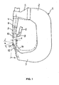
- FIG. 1 shows a joining device which determines the joining of sheet metal parts by means of punch rivets.
- the joining device comprises a C-shaped frame 1, which is usually attached to the articulated arm of an industrial robot, by means of which the joining device can be moved into the respective working position.
- a holder 3 At the upper leg 2 of the frame 1 in the drawing a holder 3 is fixed, which carries in a receiving bore a drive 4 with a longitudinally movable through this punch 5.
- the punch 5 is located inside the drive 4 and has an end face perpendicular to its longitudinal axis 6, which acts on the punch rivet to be set in each case.
- a loading device 8 which loads a feed tube 9 individually supplied punch rivets in a setting sleeve 10, in which they are in front of the end face of the punch 5 for the next joining operation be kept ready.
- a tool holder 12 On the leg 7 of the frame 1, the drive 4 opposite a tool holder 12 is arranged, which carries at its free end a tool 13, on which the workpieces are supported during the joining and acting on the workpieces reshaping.
- the tool holder 12 ensures by its axial length that the tool 13 is located at a distance from the leg 7 and thereby allows the joining of workpieces, in which the contact point for the tool 13 is arranged sunk.
- the tool 13 has a longitudinal axis 14, which coincides with unloaded frame with the longitudinal axis 6 of the punch 5.
- the surface of the tool 13 coming into contact with the workpiece during joining is designed as a surface of revolution about the longitudinal axis 14.
- FIG 1 the unloaded state of the frame 1 is indicated by dashed lines.
- the solid lines show, for clarity greatly exaggerated, the joining device under heavy load, as occurs in the final phase when setting punch rivets.
- both legs bend 37 of the frame 1 apart and thereby cause a change in position of the drive 4 and the tool 13 such that the longitudinal axes 6, 14 no longer coincide, but differ in their angular position of each other and form an angle ⁇ with each other, the Sum of the angular deviations of both longitudinal axes corresponds.
- the angle ⁇ is also the angle that the faces of the punch 5 and tool 13 in this Form load condition with each other. It is therefore also called spread angle, since it indicates the extent to which the faces of the punch and tool are spread apart.
- the tool holder is designed so that it undergoes an elastic deformation due to the load during joining, which at least partially compensates for the spreading of the legs of the frame.
- the tool holder is provided in its center with a tapered region of lesser rigidity, which is designed so that the tool holder deforms under load in the manner of a buckling in a direction which reduces the spread at the end faces of Stamp and tool causes.
- a tool holder 20 which has a suitable elastic deformation behavior.
- the tool holder 20 has a plate-shaped base 21 with a flat bottom surface 22 which serves to support on the leg of the frame.
- the foot 21 has a rear, flatter portion 23 with a mounting hole 24 and a front, higher portion 25, a head 26th wearing.
- the flatter section 23 merges steadily into the higher section 25.
- a constricted portion 27 which is dimensioned so that the head 26 tends with increasing load in the joining device in the direction of the flatter portion 23 and thereby caused by spreading of the frame angle deviation of reduced by the head 26 tool.
- the tool holder 20 has a bore 28 which penetrates the head 26, the region 27 and the portion 25 perpendicular to the bottom surface 22.
- the bore 28 serves to receive a retaining pin of a mounted on the head joining tool.
- the located in the foot 21 part of the bore 28 receives a centering pin, with which the tool holder 20 is centered on the leg of the frame coaxial with the punch of the drive.
- a lateral threaded bore 29 in the head 26 is intended to receive a clamping screw, with which the pin of the tool is clamped in the bore 28.
- In the bore 28 further opens a helical bore 30 through which a release tool for releasing the joining tool can be introduced.
- FIG. 4 shows a tool holder 40 of a tool holder 50 of medium length compared to the tool holder 20 and the tool holder 50 shown in FIG.
- the tool holder 40 has a foot 41 and a head 46.
- the foot 41 is in shape and size with the foot 21 and the head 46 in shape and size with the head 26 match.
- the greater axial length of the tool holder 40 is based solely on the greater length of an extending between foot 41 and head 46 tapered cylindrical portion 47.
- the stiffness of the region 47 is in this case matched to the axial length of the tool holder 40, that under the in the joining tool on the tool holder 40 acting load the head 46 undergoes a change in position, which partially compensates for the angular deviation caused by the spread of the frame.
- the tool holder 50 in Figure 5 also agrees with respect to his foot 51 and his head 56 with the tool holders 20 and 40 match. Its central, tapered region 57 is approximately twice as long as the region 47 of the tool holder 40 and adapted in its shape change behavior to the requirements arising at this axial length of the tool holder requirements.
- the tool holders 20, 40, 50 together form a tool holder replacement which is designed for use in a specific joining device.
- the design is carried out so that all three tool holder 20, 40, 50 in the joining tool at the same stress the same angular deviation between the longitudinal axes of the punch and tool, i. generate the same spread angle ⁇ .
- FIGS. 6 to 8 All three figures show the frame 1 of the joining device described with reference to FIG 1 in the unloaded state.
- the short tool holder 20 is attached to the leg 7 of the frame 1.
- the connected to the leg 2 holder 3, which can be mounted on the envelope, is in a first position in which the drive receiving portion has a smaller distance from the leg 7.
- a distance L 1 is present between the head of the tool holder 20 and the holder 3.
- the tool holder 20 has been replaced by the tool holder 40. This reduces the distance between the head of the tool holder 20 and the holder 3 to the smaller distance L2.
- Figure 8 shows an embodiment in which the holder 3 is mounted in the second position in which its receiving portion has a greater distance from the leg 7 of the frame 1.
- the leg 7 of the long tool holder 50 is mounted, whose greater length compensates for the greater distance of the holder 3, so that the distance between the head of the tool holder 50 and the holder 3 is again equal to L2.
- FIGS. 6 to 8 Each of the examples shown in FIGS. 6 to 8 is intended for another application and optimal.
- the three tool holders 20, 40, 50 in conjunction with the two mounting positions of the holder 3 allow six design variations.
- With the help of the inventive design of the deformation behavior of three tool holders can be brought to a small value for all six design variations of the spread angle, which varies only slightly from variation to variation.
Landscapes
- Engineering & Computer Science (AREA)
- Mechanical Engineering (AREA)
- Insertion Pins And Rivets (AREA)
- Bending Of Plates, Rods, And Pipes (AREA)
- Mounting, Exchange, And Manufacturing Of Dies (AREA)
Applications Claiming Priority (1)
| Application Number | Priority Date | Filing Date | Title |
|---|---|---|---|
| DE102005043211A DE102005043211A1 (de) | 2005-09-09 | 2005-09-09 | Fügevorrichtung zum umformtechnischen Fügen |
Publications (2)
| Publication Number | Publication Date |
|---|---|
| EP1762315A1 true EP1762315A1 (fr) | 2007-03-14 |
| EP1762315B1 EP1762315B1 (fr) | 2010-03-03 |
Family
ID=37307325
Family Applications (1)
| Application Number | Title | Priority Date | Filing Date |
|---|---|---|---|
| EP06120237A Active EP1762315B1 (fr) | 2005-09-09 | 2006-09-06 | Dispositif de connection par déformation plastique |
Country Status (5)
| Country | Link |
|---|---|
| US (1) | US7971335B2 (fr) |
| EP (1) | EP1762315B1 (fr) |
| JP (1) | JP5048289B2 (fr) |
| DE (2) | DE102005043211A1 (fr) |
| ES (1) | ES2339585T3 (fr) |
Families Citing this family (4)
| Publication number | Priority date | Publication date | Assignee | Title |
|---|---|---|---|---|
| ATE528087T1 (de) * | 2004-03-24 | 2011-10-15 | Newfrey Llc | Nietsystem zur bildung einer nietverbindung |
| US8434215B2 (en) * | 2008-08-05 | 2013-05-07 | Newfrey Llc | Self-piercing rivet setting machine |
| KR102072171B1 (ko) * | 2014-01-16 | 2020-01-31 | 아틀라스 콥코 아이에이에스 유케이 리미티드 | 리벳 방법 |
| CN110198831B (zh) * | 2017-02-06 | 2022-02-22 | 日本精工株式会社 | 框架构造、加工装置、部件的制造方法、滚动轴承的制造方法、车辆的制造方法、机械的制造方法以及冲压装置 |
Citations (6)
| Publication number | Priority date | Publication date | Assignee | Title |
|---|---|---|---|---|
| DE554810C (de) * | 1932-07-14 | Wilhelm Wiegand | Hydraulische Presse, insbesondere fuer Leder u. dgl. | |
| FR993420A (fr) * | 1949-06-20 | 1951-10-31 | Marocaine D Etudes Et De Parti | Perfectionnements aux têtes de machines-outils à outils multiples |
| JPS4897176A (fr) * | 1972-03-24 | 1973-12-11 | ||
| WO1997027972A1 (fr) * | 1996-02-03 | 1997-08-07 | Ariel Industries Plc | Procede et appareil d'alignement d'outils situes sur une presse a col de cygne |
| EP0835731A2 (fr) * | 1994-10-14 | 1998-04-15 | Engel Maschinenbau Gesellschaft Mbh | Machine à mouler par injection |
| DE102004005884A1 (de) | 2004-02-05 | 2005-08-25 | Newfrey Llc, Newark | Fügeeinrichtung |
Family Cites Families (35)
| Publication number | Priority date | Publication date | Assignee | Title |
|---|---|---|---|---|
| US281275A (en) * | 1883-07-17 | Henry f | ||
| US1312651A (en) * | 1919-08-12 | waiters | ||
| US291187A (en) * | 1884-01-01 | Joseph g | ||
| US545504A (en) * | 1895-09-03 | Saw-guard | ||
| US307112A (en) * | 1884-10-28 | Saw-guard | ||
| US611725A (en) * | 1898-10-04 | williams | ||
| FR12487E (fr) * | 1909-08-07 | 1910-09-23 | Othon Troupenat | Appareil de sécurité pour scies circulaires |
| US1037843A (en) * | 1911-10-30 | 1912-09-10 | David S Ackley | Saw-guard |
| US1207683A (en) * | 1915-11-24 | 1916-12-05 | E C Atkins & Co | Saw-guard. |
| US1258961A (en) * | 1916-03-09 | 1918-03-12 | James G Tattersall | Saw-guard and splitter. |
| US1244187A (en) * | 1917-02-17 | 1917-10-23 | Warren M Frisbie | Circular-saw guard. |
| US1720535A (en) * | 1927-12-17 | 1929-07-09 | Calmer G Wold | Automatic guard for saws |
| US1821113A (en) * | 1928-10-31 | 1931-09-01 | American Saw Mill Machinery Co | Mounting for rotary miter saws |
| US1830579A (en) * | 1930-01-30 | 1931-11-03 | Wappat Inc | Electric handsaw |
| US2572326A (en) * | 1948-07-12 | 1951-10-23 | Evans Mervyn Camille | Circular saw guard |
| US2593596A (en) * | 1949-03-24 | 1952-04-22 | George V Olson | Circular saw guard |
| US4270428A (en) * | 1979-07-25 | 1981-06-02 | Black & Decker Inc. | Kerf guide and cautionary marker for a power driven tool |
| US4765057A (en) * | 1980-02-02 | 1988-08-23 | Multifastener Corporation | Self-attaching fastener, panel assembly and installation apparatus |
| US4367668A (en) * | 1980-12-22 | 1983-01-11 | Jensen Joseph D | Circular saw attachment |
| GB2151996B (en) * | 1983-12-09 | 1987-04-23 | Trw Cam Gears Ltd | Power assisted steering system |
| JPS61154798A (ja) * | 1984-12-28 | 1986-07-14 | Koshin Giken:Kk | 片持プレス装置 |
| US4625604A (en) * | 1985-06-10 | 1986-12-02 | Hirsh Company | Splitter and blade guard assembly |
| US4875398A (en) * | 1988-01-15 | 1989-10-24 | Atlantic Richfield Company | Retractable dust control hood and guard for rotary table saw |
| US5181447A (en) * | 1991-03-25 | 1993-01-26 | Timothy Hewitt | Adjustable protecting guard apparatus for a blade of a table saw |
| US5375495A (en) * | 1992-05-18 | 1994-12-27 | Porter-Cable Corporation | Optical alignment system for circular power saws |
| US5231906A (en) * | 1992-09-30 | 1993-08-03 | Julien Kogej | Table saw guard |
| US5794351A (en) * | 1996-05-31 | 1998-08-18 | Black & Decker, Inc. | Window assembly and lower saw guard for circular saw |
| US5857507A (en) * | 1996-09-20 | 1999-01-12 | Black & Decker Inc. | Table saw |
| CN1259892A (zh) * | 1997-06-09 | 2000-07-12 | 伊利克特拉贝库姆股份公司 | 移动式台式圆盘锯 |
| US6405624B2 (en) * | 1998-07-08 | 2002-06-18 | Delta International Machinery Corp. | Splitter and cutting member guard assembly |
| JP3742347B2 (ja) * | 2002-01-24 | 2006-02-01 | 福井鋲螺株式会社 | 締結状態の監視方法及びこの方法を用いる締結装置 |
| CN1485163A (zh) * | 2002-09-27 | 2004-03-31 | 顺德市顺达电脑厂有限公司 | 无孔铆接装置及其铆接件 |
| WO2004041490A2 (fr) * | 2002-10-31 | 2004-05-21 | Delta International Machinery Corp. | Scie circulaire a table a double chanfrein |
| GB2417452B (en) * | 2004-08-24 | 2006-11-08 | Ford Global Tech Llc | A self pierce rivet die |
| US7849573B2 (en) * | 2006-09-08 | 2010-12-14 | Ford Motor Company | Apparatus for self-piercing rivet |
-
2005
- 2005-09-09 DE DE102005043211A patent/DE102005043211A1/de not_active Withdrawn
-
2006
- 2006-08-29 JP JP2006231844A patent/JP5048289B2/ja active Active
- 2006-09-06 EP EP06120237A patent/EP1762315B1/fr active Active
- 2006-09-06 DE DE502006006316T patent/DE502006006316D1/de active Active
- 2006-09-06 ES ES06120237T patent/ES2339585T3/es active Active
- 2006-09-08 US US11/517,275 patent/US7971335B2/en active Active
Patent Citations (6)
| Publication number | Priority date | Publication date | Assignee | Title |
|---|---|---|---|---|
| DE554810C (de) * | 1932-07-14 | Wilhelm Wiegand | Hydraulische Presse, insbesondere fuer Leder u. dgl. | |
| FR993420A (fr) * | 1949-06-20 | 1951-10-31 | Marocaine D Etudes Et De Parti | Perfectionnements aux têtes de machines-outils à outils multiples |
| JPS4897176A (fr) * | 1972-03-24 | 1973-12-11 | ||
| EP0835731A2 (fr) * | 1994-10-14 | 1998-04-15 | Engel Maschinenbau Gesellschaft Mbh | Machine à mouler par injection |
| WO1997027972A1 (fr) * | 1996-02-03 | 1997-08-07 | Ariel Industries Plc | Procede et appareil d'alignement d'outils situes sur une presse a col de cygne |
| DE102004005884A1 (de) | 2004-02-05 | 2005-08-25 | Newfrey Llc, Newark | Fügeeinrichtung |
Also Published As
| Publication number | Publication date |
|---|---|
| US20070056153A1 (en) | 2007-03-15 |
| JP2007075894A (ja) | 2007-03-29 |
| DE502006006316D1 (de) | 2010-04-15 |
| ES2339585T3 (es) | 2010-05-21 |
| DE102005043211A1 (de) | 2007-03-15 |
| US7971335B2 (en) | 2011-07-05 |
| EP1762315B1 (fr) | 2010-03-03 |
| JP5048289B2 (ja) | 2012-10-17 |
Similar Documents
| Publication | Publication Date | Title |
|---|---|---|
| EP3362212B1 (fr) | Outil d'usinage par enlèvement de copeaux | |
| DE102006019405A1 (de) | Werkzeug zur Kaltexpansion von Löchern | |
| DE102017203943B4 (de) | Setzeinheit und Verfahren zum Setzen eines Verbindungselements an einem Werkstück | |
| EP2747922B1 (fr) | Procédé et dispositif pour fixer une pièce sur une partie de machine rotative | |
| EP3166751B1 (fr) | Dispositif de compression servant à comprimer une bande de finition sur les surfaces de pièces | |
| EP2688709B2 (fr) | Procédé, outil et machine et pour calibrer des coussinets | |
| DE102008033933B4 (de) | Verarbeitungswerkzeug sowie Verfahren zum Überführen eines Bauteils aus einer Bereitstellungsposition in eine Verarbeitungsposition | |
| EP3505270B1 (fr) | Unité de frappe pour un dispositif de poinçonnage, dispositif de poinçonnage et procédé de fabrication d'un tel dispositif de poinçonnage | |
| EP1762315B1 (fr) | Dispositif de connection par déformation plastique | |
| EP3093102A1 (fr) | Lunette | |
| DE3041650C2 (de) | Rollkupplungsfutter | |
| EP3242760A1 (fr) | Dispositif et procédé pour poser un élément de liaison sur une pièce | |
| DE102006033608B3 (de) | Lagervorrichtung | |
| DE19917146A1 (de) | Nullpunktspannsystem | |
| DE3151275C2 (de) | Befestigungsvorrichtung für Werkzeuge | |
| EP1049555B1 (fr) | Pince de serrage destinee a retenir des barres dans des tours | |
| DE3001805C2 (fr) | ||
| WO2011138157A1 (fr) | Porte-outil, machine-outil comprenant un tel porte-outil, et procédé pour fixer un outil d'usinage sur un porte-outil d'une machine-outil | |
| DE102017123723B4 (de) | Hydraulisches Stanzgerät | |
| EP0362753B1 (fr) | Dispositif de fixation | |
| DE102019211532B4 (de) | Verarbeitungswerkzeug zum Überführen eines Bauteils aus einer Bereitstellungsposition in eine Verarbeitungsposition | |
| DE102020004165A1 (de) | Positionseinstellvorrichtung und Ultrapräzisions-Werkzeugmaschine | |
| AT506831B1 (de) | Verfahren zum kalibrieren von lagerbuchsen | |
| DE19816198C2 (de) | Nietverfahren und Nieteinrichtung zum Vernieten von mehreren, aus unterschiedlichen Werkstoffen bestehenden Werkstücken | |
| DE2025515A1 (de) | Spannvorrichtung |
Legal Events
| Date | Code | Title | Description |
|---|---|---|---|
| PUAI | Public reference made under article 153(3) epc to a published international application that has entered the european phase |
Free format text: ORIGINAL CODE: 0009012 |
|
| AK | Designated contracting states |
Kind code of ref document: A1 Designated state(s): AT BE BG CH CY CZ DE DK EE ES FI FR GB GR HU IE IS IT LI LT LU LV MC NL PL PT RO SE SI SK TR |
|
| AX | Request for extension of the european patent |
Extension state: AL BA HR MK YU |
|
| 17P | Request for examination filed |
Effective date: 20070830 |
|
| 17Q | First examination report despatched |
Effective date: 20071005 |
|
| AKX | Designation fees paid |
Designated state(s): DE ES FR GB SE |
|
| GRAP | Despatch of communication of intention to grant a patent |
Free format text: ORIGINAL CODE: EPIDOSNIGR1 |
|
| GRAS | Grant fee paid |
Free format text: ORIGINAL CODE: EPIDOSNIGR3 |
|
| GRAA | (expected) grant |
Free format text: ORIGINAL CODE: 0009210 |
|
| AK | Designated contracting states |
Kind code of ref document: B1 Designated state(s): DE ES FR GB SE |
|
| REG | Reference to a national code |
Ref country code: GB Ref legal event code: FG4D Free format text: NOT ENGLISH |
|
| REF | Corresponds to: |
Ref document number: 502006006316 Country of ref document: DE Date of ref document: 20100415 Kind code of ref document: P |
|
| REG | Reference to a national code |
Ref country code: ES Ref legal event code: FG2A Ref document number: 2339585 Country of ref document: ES Kind code of ref document: T3 |
|
| REG | Reference to a national code |
Ref country code: SE Ref legal event code: TRGR |
|
| PLBE | No opposition filed within time limit |
Free format text: ORIGINAL CODE: 0009261 |
|
| STAA | Information on the status of an ep patent application or granted ep patent |
Free format text: STATUS: NO OPPOSITION FILED WITHIN TIME LIMIT |
|
| 26N | No opposition filed |
Effective date: 20101206 |
|
| REG | Reference to a national code |
Ref country code: ES Ref legal event code: FD2A Effective date: 20111019 |
|
| PG25 | Lapsed in a contracting state [announced via postgrant information from national office to epo] |
Ref country code: ES Free format text: LAPSE BECAUSE OF NON-PAYMENT OF DUE FEES Effective date: 20100907 |
|
| REG | Reference to a national code |
Ref country code: FR Ref legal event code: PLFP Year of fee payment: 11 |
|
| REG | Reference to a national code |
Ref country code: FR Ref legal event code: PLFP Year of fee payment: 12 |
|
| REG | Reference to a national code |
Ref country code: FR Ref legal event code: PLFP Year of fee payment: 13 |
|
| PGFP | Annual fee paid to national office [announced via postgrant information from national office to epo] |
Ref country code: FR Payment date: 20190815 Year of fee payment: 14 Ref country code: SE Payment date: 20190910 Year of fee payment: 14 |
|
| PG25 | Lapsed in a contracting state [announced via postgrant information from national office to epo] |
Ref country code: FR Free format text: LAPSE BECAUSE OF NON-PAYMENT OF DUE FEES Effective date: 20200930 |
|
| PG25 | Lapsed in a contracting state [announced via postgrant information from national office to epo] |
Ref country code: SE Free format text: LAPSE BECAUSE OF NON-PAYMENT OF DUE FEES Effective date: 20200907 |
|
| REG | Reference to a national code |
Ref country code: SE Ref legal event code: EUG |
|
| PGFP | Annual fee paid to national office [announced via postgrant information from national office to epo] |
Ref country code: GB Payment date: 20230713 Year of fee payment: 18 |
|
| PGFP | Annual fee paid to national office [announced via postgrant information from national office to epo] |
Ref country code: DE Payment date: 20230712 Year of fee payment: 18 |