EP1761968B1 - System zur überwachung einer gruppe von elektrochemischen zellen und zugehörige vorrichtung - Google Patents
System zur überwachung einer gruppe von elektrochemischen zellen und zugehörige vorrichtung Download PDFInfo
- Publication number
- EP1761968B1 EP1761968B1 EP05762728A EP05762728A EP1761968B1 EP 1761968 B1 EP1761968 B1 EP 1761968B1 EP 05762728 A EP05762728 A EP 05762728A EP 05762728 A EP05762728 A EP 05762728A EP 1761968 B1 EP1761968 B1 EP 1761968B1
- Authority
- EP
- European Patent Office
- Prior art keywords
- frequency
- voltage
- monitoring system
- monitoring
- cell
- Prior art date
- Legal status (The legal status is an assumption and is not a legal conclusion. Google has not performed a legal analysis and makes no representation as to the accuracy of the status listed.)
- Expired - Lifetime
Links
- 238000012544 monitoring process Methods 0.000 title claims abstract description 25
- 230000006835 compression Effects 0.000 claims description 2
- 238000007906 compression Methods 0.000 claims description 2
- 238000010276 construction Methods 0.000 claims 1
- 239000000446 fuel Substances 0.000 abstract description 5
- 238000005259 measurement Methods 0.000 description 7
- 238000001514 detection method Methods 0.000 description 5
- 239000004020 conductor Substances 0.000 description 4
- 239000003990 capacitor Substances 0.000 description 3
- 230000032683 aging Effects 0.000 description 2
- 238000010586 diagram Methods 0.000 description 2
- 238000012423 maintenance Methods 0.000 description 2
- 230000010287 polarization Effects 0.000 description 2
- 230000035945 sensitivity Effects 0.000 description 2
- 229920002449 FKM Polymers 0.000 description 1
- UFHFLCQGNIYNRP-UHFFFAOYSA-N Hydrogen Chemical compound [H][H] UFHFLCQGNIYNRP-UHFFFAOYSA-N 0.000 description 1
- 230000005856 abnormality Effects 0.000 description 1
- 239000003153 chemical reaction reagent Substances 0.000 description 1
- 230000008878 coupling Effects 0.000 description 1
- 238000010168 coupling process Methods 0.000 description 1
- 238000005859 coupling reaction Methods 0.000 description 1
- 238000003708 edge detection Methods 0.000 description 1
- 229920001971 elastomer Polymers 0.000 description 1
- 239000000806 elastomer Substances 0.000 description 1
- 230000008642 heat stress Effects 0.000 description 1
- 229910052739 hydrogen Inorganic materials 0.000 description 1
- 239000001257 hydrogen Substances 0.000 description 1
- 238000002347 injection Methods 0.000 description 1
- 239000007924 injection Substances 0.000 description 1
- 239000000463 material Substances 0.000 description 1
- 230000010363 phase shift Effects 0.000 description 1
- 230000000630 rising effect Effects 0.000 description 1
- 239000000243 solution Substances 0.000 description 1
- 230000001360 synchronised effect Effects 0.000 description 1
- 238000003466 welding Methods 0.000 description 1
Images


Classifications
-
- H—ELECTRICITY
- H01—ELECTRIC ELEMENTS
- H01M—PROCESSES OR MEANS, e.g. BATTERIES, FOR THE DIRECT CONVERSION OF CHEMICAL ENERGY INTO ELECTRICAL ENERGY
- H01M8/00—Fuel cells; Manufacture thereof
- H01M8/04—Auxiliary arrangements, e.g. for control of pressure or for circulation of fluids
- H01M8/04298—Processes for controlling fuel cells or fuel cell systems
- H01M8/04313—Processes for controlling fuel cells or fuel cell systems characterised by the detection or assessment of variables; characterised by the detection or assessment of failure or abnormal function
- H01M8/04537—Electric variables
- H01M8/04634—Other electric variables, e.g. resistance or impedance
- H01M8/04641—Other electric variables, e.g. resistance or impedance of the individual fuel cell
-
- G—PHYSICS
- G01—MEASURING; TESTING
- G01R—MEASURING ELECTRIC VARIABLES; MEASURING MAGNETIC VARIABLES
- G01R31/00—Arrangements for testing electric properties; Arrangements for locating electric faults; Arrangements for electrical testing characterised by what is being tested not provided for elsewhere
- G01R31/36—Arrangements for testing, measuring or monitoring the electrical condition of accumulators or electric batteries, e.g. capacity or state of charge [SoC]
- G01R31/396—Acquisition or processing of data for testing or for monitoring individual cells or groups of cells within a battery
-
- H—ELECTRICITY
- H01—ELECTRIC ELEMENTS
- H01M—PROCESSES OR MEANS, e.g. BATTERIES, FOR THE DIRECT CONVERSION OF CHEMICAL ENERGY INTO ELECTRICAL ENERGY
- H01M8/00—Fuel cells; Manufacture thereof
- H01M8/24—Grouping of fuel cells, e.g. stacking of fuel cells
- H01M8/249—Grouping of fuel cells, e.g. stacking of fuel cells comprising two or more groupings of fuel cells, e.g. modular assemblies
-
- H—ELECTRICITY
- H01—ELECTRIC ELEMENTS
- H01M—PROCESSES OR MEANS, e.g. BATTERIES, FOR THE DIRECT CONVERSION OF CHEMICAL ENERGY INTO ELECTRICAL ENERGY
- H01M8/00—Fuel cells; Manufacture thereof
- H01M8/04—Auxiliary arrangements, e.g. for control of pressure or for circulation of fluids
- H01M8/04223—Auxiliary arrangements, e.g. for control of pressure or for circulation of fluids during start-up or shut-down; Depolarisation or activation, e.g. purging; Means for short-circuiting defective fuel cells
- H01M8/04246—Short circuiting means for defective fuel cells
-
- Y—GENERAL TAGGING OF NEW TECHNOLOGICAL DEVELOPMENTS; GENERAL TAGGING OF CROSS-SECTIONAL TECHNOLOGIES SPANNING OVER SEVERAL SECTIONS OF THE IPC; TECHNICAL SUBJECTS COVERED BY FORMER USPC CROSS-REFERENCE ART COLLECTIONS [XRACs] AND DIGESTS
- Y02—TECHNOLOGIES OR APPLICATIONS FOR MITIGATION OR ADAPTATION AGAINST CLIMATE CHANGE
- Y02E—REDUCTION OF GREENHOUSE GAS [GHG] EMISSIONS, RELATED TO ENERGY GENERATION, TRANSMISSION OR DISTRIBUTION
- Y02E60/00—Enabling technologies; Technologies with a potential or indirect contribution to GHG emissions mitigation
- Y02E60/30—Hydrogen technology
- Y02E60/50—Fuel cells
Definitions
- the present invention relates to a system for monitoring a set of electrochemical cells arranged in series. It also relates to a connection device for the realization of said monitoring system.
- the invention finds a particularly advantageous application in the field of fuel cells composed of an assembly of electrochemical cells electrically placed in series.
- Each cell of a fuel cell delivers a DC voltage that depends on the requested current, the operating conditions (reagent supply, humidity, temperature) and the electrochemical performance of the components. This voltage is, during normal operation, between a minimum voltage of 0.5 V and 1 V.
- monitoring of cell voltages allows early detection of the failure and ensures that the repair is done with the least possible discontinuity in the supply of energy to the customer.
- the currently known surveillance systems are based on successive measurements of the individual voltages of the cells by means of an acquisition system connected to each of the cells and processed so computer science.
- the document DE 100 59 392 discloses a fuel cell each of which is connected in parallel with a diode. These systems require complex and expensive measurement means. They are further complicated by the fact that the differential voltage measurements at the terminals of each cell must be made with very large common-mode voltages, for example about 100 V for the highest voltage of a stack of 100 cells. This increases the constraints on the components and the associated architecture.
- the device for connecting to the cells is generally an important cost element.
- the technical problem to be solved by the object of the present invention is to propose a system for monitoring a set of n electrochemical cells arranged in series, each cell being intended to deliver a DC voltage greater than a minimum value, which would provide effective cell monitoring but however simpler and less expensive than with known systems.
- the measurement of said high-frequency conductivity parameter gives an overall visibility on the operating state of all the electrochemical cells. Indeed, if at least one cell of the assembly fails to provide a voltage lower than the conductivity threshold of the corresponding electronic component, a break will occur in the conductivity of the component chain. This break, detected by the measurement of the conductivity parameter, will indicate an anomaly and will provoke the intervention of the maintenance service in charge of the battery of cells.
- the indication of the abnormality of the value of the measured conductivity parameter is obtained by the monitoring system because, according to the invention, it also comprises a comparator capable of comparing said high-frequency conductivity parameter with a given threshold.
- said measured conductivity parameter is the high-frequency impedance of all the components.
- the invention provides that said electronic components are diodes.
- FIG. 1 On the figure 1 is shown a monitoring system of a set of n electrochemical cells arranged in series. These cells, such as fuel cells, are respectively referenced C1, C2,..., Ci,..., Cn and deliver at their terminals a DC voltage V1, V2,..., Vi,. Vn whose value in normal operation is greater than a minimum value Vmin of 0.2 V for example.
- said monitoring system comprises a set of n electronic components which, in the embodiment shown, are Schottky diodes D1, D2, ..., Di, ..., Dn arranged in series. These diodes have a conductivity threshold voltage Vs of 0.3 V to 0.6 V, preferably greater than the minimum operating voltage Vmin of cells C1, C2,..., Ci,..., Cn.
- the number n of diodes is equal to the number n of cells to be evaluated, each cell Ci being associated with a diode Di in the sense that each diode Di is biased by the voltage Vi of the single cell Ci.
- the polarization of the diodes is carried out by means of low-frequency link elements, here inductances Li, placed between the series of cells Ci and the series of diodes Di.
- inductances Li are, at low frequency and therefore for direct current, equivalent to closed circuits.
- they behave as open circuits and decouple the voltages across the diodes of the direct voltages Vi across the cells.
- a generator G applies across the series of diodes an alternating voltage of frequency between 300 and 5000 kHz, preferably 1000 to 3000 kHz, and amplitude between 1 and 300 mV, preferably 20 to 100 mV.
- the impedance, or current, of the series of diodes Di at the selected high frequency is then measured by means of a detector D.
- a simple capacitance C or a coupling by mutual inductances is sufficient to decouple the reading of the impedance from the high value of the continuous voltage and solves the problem of "common mode" mentioned above.
- the voltage Vi applied to each diode Di is greater than the threshold voltage Vs and the impedance of all the diodes is equivalent to a series of resistors.
- the measured impedance becomes that of an open circuit.
- the value obtained for the impedance of the diodes is compared at the output of the detector D to a threshold s by a comparator S in order to make it possible to decide whether the operation of the cells is normal or if a problem arises. In this case, it is then possible to take the necessary measures: changes in the operating conditions until finding a correct operation, or maintenance, ...
- the detector D used is advantageously a synchronous detector applying a frequency reference vs from the generator G to the output signal v from the series of diodes and applied to the generator input. This type of detection reduces the sensitivity of the measurement to disturbances.
- the inductances Li chosen are of axial inductances of value between 3 and 1000 ⁇ H, preferably 50 to 500 ⁇ H.
- the diodes Di are of the small signal type, preferably of Schottky type BAT41, BAT42 or BAT43 or type 1 N4148 diodes.
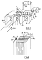
- a connection device for the realization of the surveillance system of the figure 1 is illustrated on the figure 2 .
- connection device consists of a set of n staples Ai, each associated with an electrochemical cell Ci.
- the staples Ai are made of elastomer or an equivalent material (Hytrel, Viton, etc.). Each clip Ai supports, without welding, an inductance Li whose end ei is intended to be connected to a terminal of the corresponding cell Ci. As the figure 2 , connection conductors inductances are arranged in recesses 10, 10 'formed on the walls of the staples.
- Each clip Ai also receives, always seamless, a diode Di, a connecting conductor of the diode Di being introduced into a hole 20 of the clip Ai, the other connecting conductor being introduced into the corresponding hole 20 of a staple Ai + 1 neighbor.
- the clip Ai receives through a hole 30 a connecting lead of the diode Di-1 of another clip Ai-1 neighbor.
- the other end ei of the inductor as well as the connecting conductors of the diodes Di and Di-1 open out of the clip Ai with sufficient coverage to make it possible to make an electrical contact between these three components by compression during the assembly of cells Ci constituting the battery of cells shown on the figure 3 .
- the electronic circuit for failure detection of a cell consists of a set of three Schmitt triggers IC1A, IC1C, IC1E mounted symmetrically with resistors and capacitors that make it possible to create three square signals with a frequency of between 1.5 and 3 Mhz and in phase shift of 2 ⁇ / 3.
- One of these phases is injected by the circuit IC1F into a set of mutual inductances L1 and L2 forming a transformer, after reducing its amplitude.
- the signal is then recovered by another set of mutual inductances L3 and L4, amplified and added with a constant, created by the IC3 circuit or by a Zener diode, by an inverter amplifier IC2A operational amplifier, with an amplifier whose characteristics allow the work at frequencies up to 10 MHz, for example type LM 6172 or LM 6182.
- a second sum of positive voltage is achieved by inversion with the second amplifier IC2B present in the amplifier housing.
- Each phase serves as a bias to a set of two transistors that alternately charge a capacitor C8, C9, C10. This produces a detection at the precise frequency injected into the set of diodes placed in parallel cells.
- the signal injection by L1 and L2 is applied and suppressed alternately with a frequency of the order of 100 Hz thanks to the IC4D circuit and the transistor Q7.
- a rising edge detection on the voltages of the capacitors C8, C9 and C10, added with an OR function by the diodes D1, D2 and D3, then a filter, makes it possible to create an output by the circuit IC5A whose detection threshold can be adjusted by means of the resistors R23, R25 and R29.
Landscapes
- Chemical Kinetics & Catalysis (AREA)
- Electrochemistry (AREA)
- Life Sciences & Earth Sciences (AREA)
- Engineering & Computer Science (AREA)
- Manufacturing & Machinery (AREA)
- Sustainable Development (AREA)
- General Chemical & Material Sciences (AREA)
- Sustainable Energy (AREA)
- Chemical & Material Sciences (AREA)
- Physics & Mathematics (AREA)
- General Physics & Mathematics (AREA)
- Investigating Or Analyzing Materials By The Use Of Electric Means (AREA)
- Battery Mounting, Suspending (AREA)
- Fuel Cell (AREA)
- Secondary Cells (AREA)
- Apparatus Associated With Microorganisms And Enzymes (AREA)
Claims (7)
- System zur Überwachung einer Gesamtheit von n elektrochemischen Zellen (C1, ..., Ci, ..., Cn), die in Reihe angeordnet sind, wobei jede Zelle (Ci) eine Gleichspannung (Vi) bereitstellen soll, die größer als ein Mindestwert (Vmin) ist, dadurch gekennzeichnet, dass dieses Überwachungssystem Folgendes aufweist:- eine entsprechende Gesamtheit von n elektronischen Komponenten (D1, ..., Di, ..., Dn), die in Reihe angeordnet sind, wobei jede Komponente (Di) durch die Gleichspannung (Vi) einer entsprechenden Zelle (Ci) mittels eines Niederfrequenz-Verbindungselements (Li) polarisiert wird und eine Leitfähigkeits-Schwellenspannung (Vs) aufweist, die mindestens gleich dem Mindestwert (Vmin) ist,- ein Mittel (D) zur Messung eines Hochfrequenz-Leitfähigkeitsparameters der Gesamtheit dieser Komponenten.
- System zur Überwachung nach Anspruch 1, dadurch gekennzeichnet, dass es ebenfalls einen Komparator (S) aufweist, der den Hochfrequenz-Leitfähigkeitsparameter mit einer gegebenen Schwelle (s) vergleichen kann.
- System zur Überwachung nach einem der Ansprüche 1 oder 2, dadurch gekennzeichnet, dass der gemessene Leitfähigkeitsparameter die Hochfrequenz-Impedanz der Gesamtheit von Komponenten ist.
- System zur Überwachung nach einem der Ansprüche 1 bis 3, dadurch gekennzeichnet, dass die elektronischen Komponenten Dioden (Di) sind.
- System zur Überwachung nach einem der Ansprüche 1 bis 4, dadurch gekennzeichnet, dass das Niederfrequenz-Verbindungselement eine Induktivität (Li) ist.
- Verbindungsvorrichtung zur Verwirklichung eines Überwachungssystems nach einem der Ansprüche 1 bis 5, dadurch gekennzeichnet, dass die Vorrichtung aus einer Gesamtheit von n Klammern (A1, ..., Ai, ..., An) gebildet ist, wobei jede Klammer (Ai) Folgendes stützt:- ein Niederfrequenz-Verbindungselement (Li), wovon ein Ende (ei) an einer Klemme einer entsprechenden Zelle (Ci) angeschlossen ist,- eine elektronische Komponente (Di),und wobei jede Klammer (Ai) ein Ende der elektronischen Komponente (Di-1) einer benachbarten Klammer (Ai-1) aufnimmt,
das andere Ende (e'i) des Niederfrequenz-Verbindungselements (Li), ein Ende der elektronischen Komponente (Di) und das Ende der benachbarten elektronischen Komponente (Di-1) untereinander verbunden sind. - Verbindungsvorrichtung nach Anspruch 6, dadurch gekennzeichnet, dass die Enden durch Druck untereinander verbunden sind.
Applications Claiming Priority (2)
| Application Number | Priority Date | Filing Date | Title |
|---|---|---|---|
| FR0406523A FR2871944B1 (fr) | 2004-06-16 | 2004-06-16 | Systeme de surveillance d'un ensemble de cellules electrochimiques et dispositif de realisation |
| PCT/FR2005/050332 WO2006003332A1 (fr) | 2004-06-16 | 2005-05-17 | Systeme de surveillance d'un ensemble de cellules electrochimiques et dispositif de realisation |
Publications (2)
| Publication Number | Publication Date |
|---|---|
| EP1761968A1 EP1761968A1 (de) | 2007-03-14 |
| EP1761968B1 true EP1761968B1 (de) | 2009-04-08 |
Family
ID=34946205
Family Applications (1)
| Application Number | Title | Priority Date | Filing Date |
|---|---|---|---|
| EP05762728A Expired - Lifetime EP1761968B1 (de) | 2004-06-16 | 2005-05-17 | System zur überwachung einer gruppe von elektrochemischen zellen und zugehörige vorrichtung |
Country Status (7)
| Country | Link |
|---|---|
| US (1) | US7638972B2 (de) |
| EP (1) | EP1761968B1 (de) |
| AT (1) | ATE428193T1 (de) |
| CA (1) | CA2568266A1 (de) |
| DE (1) | DE602005013780D1 (de) |
| FR (1) | FR2871944B1 (de) |
| WO (1) | WO2006003332A1 (de) |
Families Citing this family (3)
| Publication number | Priority date | Publication date | Assignee | Title |
|---|---|---|---|---|
| US7927758B2 (en) * | 2006-01-11 | 2011-04-19 | Samsung Sdi Co., Ltd. | Gasket being capable of measuring voltage and fuel cell system having the same |
| US11223074B2 (en) * | 2017-10-16 | 2022-01-11 | Neapco Intellectual Property Holdings, Llc | Battery cell monitoring system |
| JP6992568B2 (ja) * | 2018-02-14 | 2022-02-04 | トヨタ自動車株式会社 | 燃料電池のエージング装置 |
Family Cites Families (7)
| Publication number | Priority date | Publication date | Assignee | Title |
|---|---|---|---|---|
| ZA727389B (en) | 1971-11-22 | 1973-06-27 | American Optical Corp | Heart pacer supply failure protection apparatus |
| EP0985239A1 (de) * | 1997-04-10 | 2000-03-15 | Magnet-Motor Gesellschaft Für Magnetmotorische Technik Mbh | Kühlung und befeuchtung von polymerelektrolyt-brennstoffzellen |
| DE19827880C1 (de) | 1998-06-23 | 1999-12-23 | Dbb Full Cell Engines Gmbh | Schaltungsanordnung für ein Brennstoffzellenverbundsystem und Verfahren zum Betreiben einer solchen Schaltungsanordnung |
| DE19907369C2 (de) | 1999-02-20 | 2002-12-12 | Forschungszentrum Juelich Gmbh | Stromquelle mit in Serie geschalteten Zellen |
| DE10043139B4 (de) * | 2000-08-31 | 2015-10-29 | Heliocentris Fuel Cell Solutions Gmbh | Verfahren zur Überwachung von Brennstoffzellenstapeln und Überwachungseinheit |
| DE10059392A1 (de) * | 2000-11-30 | 2002-06-20 | Siemens Ag | Gleichstromversorgungseinrichtung mit mehreren seriell angeordneten Brennstoffzellenblöcken |
| JP2005526365A (ja) * | 2002-05-17 | 2005-09-02 | グリーンライト パワー テクノロジーズ、インコーポレイテッド | 燃料電池及び燃料電池構成要素における障害状況を指示する方法及び装置 |
-
2004
- 2004-06-16 FR FR0406523A patent/FR2871944B1/fr not_active Expired - Fee Related
-
2005
- 2005-05-17 DE DE602005013780T patent/DE602005013780D1/de not_active Expired - Lifetime
- 2005-05-17 AT AT05762728T patent/ATE428193T1/de not_active IP Right Cessation
- 2005-05-17 US US11/569,793 patent/US7638972B2/en not_active Expired - Fee Related
- 2005-05-17 CA CA002568266A patent/CA2568266A1/fr not_active Abandoned
- 2005-05-17 WO PCT/FR2005/050332 patent/WO2006003332A1/fr not_active Ceased
- 2005-05-17 EP EP05762728A patent/EP1761968B1/de not_active Expired - Lifetime
Also Published As
| Publication number | Publication date |
|---|---|
| US7638972B2 (en) | 2009-12-29 |
| EP1761968A1 (de) | 2007-03-14 |
| WO2006003332A1 (fr) | 2006-01-12 |
| FR2871944A1 (fr) | 2005-12-23 |
| CA2568266A1 (fr) | 2006-01-12 |
| ATE428193T1 (de) | 2009-04-15 |
| DE602005013780D1 (de) | 2009-05-20 |
| FR2871944B1 (fr) | 2006-07-28 |
| US20080197852A1 (en) | 2008-08-21 |
Similar Documents
| Publication | Publication Date | Title |
|---|---|---|
| EP2719012B1 (de) | Vorrichtung zur überwachung des spannungsausgangs der zellen eines elektrochemischen generators | |
| EP2419749B1 (de) | Verfahren zum diagnostizieren des ausfalls eines photovoltaikgenerators | |
| FR2694978A1 (fr) | Système de mesure d'impédance de batteries en ligne. | |
| EP2397863A1 (de) | Verfahren zur Überwachung des Zustands einer Batterie | |
| EP2401623A1 (de) | Verfahren zum charakterisieren eines elektrischen systems durch impedanzspektroskopie | |
| EP4232834A1 (de) | Verfahren zur erkennung eines fehlers einer batteriemodulgruppe | |
| FR3126157A1 (fr) | Vérification de la précision métrologique d’un compteur électrique | |
| EP1761968B1 (de) | System zur überwachung einer gruppe von elektrochemischen zellen und zugehörige vorrichtung | |
| WO2022200241A1 (fr) | Procédé et système pour estimer un indicateur de vieillissement d'une batterie électrique rechargeable | |
| EP4300112B1 (de) | Neutralverlustdetektion | |
| FR2988854A1 (fr) | Circuit et procede de surveillance d'une separation des potentiels | |
| EP3358307B1 (de) | Verfahren zur verwaltung einer hilfsstromversorgung eines zählers und entsprechender zähler sowie programm und speichermedium | |
| EP3709481B1 (de) | Steuerverfahren eines kontaktlosen aufladesystems, und entsprechendes kontaktloses aufladesystem | |
| EP4155738B1 (de) | Erkennung einer fehlerhaften klemme | |
| EP4205146A1 (de) | Stromkabel mit integriertem autonomem kommunizierendem messsystem | |
| EP3961239B1 (de) | Überprüfung der genauigkeit der von einem stromzähler vorgenommenen messungen | |
| EP3813168A1 (de) | Brennstoffzelle, die für die charakterisierung mindestens eines in einem reaktiven gas enthaltenen schadstoffes geeignet ist | |
| FR2748608A1 (fr) | Systeme electronique pour batterie bipolaire et carte pour ce systeme | |
| WO2011048062A1 (fr) | Dispositif de mesure de tension pour batterie et dispositif de contrôle associé | |
| EP4266065B1 (de) | Stromzähler zur erkennung einer betrügerischen öffnung | |
| EP3341985B1 (de) | Batterie zur sicherstellung der bestimmung der elektrischen spannung der anschlüsse der elektrischen verbindungselemente zwischen den speicherelementen | |
| EP2319117B1 (de) | Vorrichtung zur numerischen darstellung einer spannung | |
| EP3381120B1 (de) | System zur steuerung der stromversorgung eines elektrisch betriebenen fahrzeugs mit mindestens zwei elektrischen zugmaschinen | |
| EP4718097A1 (de) | Physikalische kernmessung eines elektrochemischen akkumulators | |
| FR3005166A1 (fr) | Procede et dispositif de determination d'une energie electrique consommee par une installation electrique. |
Legal Events
| Date | Code | Title | Description |
|---|---|---|---|
| PUAI | Public reference made under article 153(3) epc to a published international application that has entered the european phase |
Free format text: ORIGINAL CODE: 0009012 |
|
| 17P | Request for examination filed |
Effective date: 20070116 |
|
| AK | Designated contracting states |
Kind code of ref document: A1 Designated state(s): AT BE BG CH CY CZ DE DK EE ES FI FR GB GR HU IE IS IT LI LT LU MC NL PL PT RO SE SI SK TR |
|
| AX | Request for extension of the european patent |
Extension state: AL BA HR LV MK YU |
|
| RAP1 | Party data changed (applicant data changed or rights of an application transferred) |
Owner name: L'AIR LIQUIDE, SOCIETE ANONYME POUR L'ETUDE ET L'E |
|
| RAP1 | Party data changed (applicant data changed or rights of an application transferred) |
Owner name: L'AIR LIQUIDE, SOCIETE ANONYME POUR L'ETUDE ET L'E |
|
| 17Q | First examination report despatched |
Effective date: 20070626 |
|
| GRAP | Despatch of communication of intention to grant a patent |
Free format text: ORIGINAL CODE: EPIDOSNIGR1 |
|
| GRAP | Despatch of communication of intention to grant a patent |
Free format text: ORIGINAL CODE: EPIDOSNIGR1 |
|
| GRAS | Grant fee paid |
Free format text: ORIGINAL CODE: EPIDOSNIGR3 |
|
| GRAA | (expected) grant |
Free format text: ORIGINAL CODE: 0009210 |
|
| AK | Designated contracting states |
Kind code of ref document: B1 Designated state(s): AT BE BG CH CY CZ DE DK EE ES FI FR GB GR HU IE IS IT LI LT LU MC NL PL PT RO SE SI SK TR |
|
| AX | Request for extension of the european patent |
Extension state: AL BA HR LV MK YU |
|
| REG | Reference to a national code |
Ref country code: GB Ref legal event code: FG4D Free format text: NOT ENGLISH |
|
| REG | Reference to a national code |
Ref country code: CH Ref legal event code: EP |
|
| REG | Reference to a national code |
Ref country code: IE Ref legal event code: FG4D |
|
| REF | Corresponds to: |
Ref document number: 602005013780 Country of ref document: DE Date of ref document: 20090520 Kind code of ref document: P |
|
| PG25 | Lapsed in a contracting state [announced via postgrant information from national office to epo] |
Ref country code: SI Free format text: LAPSE BECAUSE OF FAILURE TO SUBMIT A TRANSLATION OF THE DESCRIPTION OR TO PAY THE FEE WITHIN THE PRESCRIBED TIME-LIMIT Effective date: 20090408 |
|
| NLV1 | Nl: lapsed or annulled due to failure to fulfill the requirements of art. 29p and 29m of the patents act | ||
| REG | Reference to a national code |
Ref country code: IE Ref legal event code: FD4D |
|
| PG25 | Lapsed in a contracting state [announced via postgrant information from national office to epo] |
Ref country code: FI Free format text: LAPSE BECAUSE OF FAILURE TO SUBMIT A TRANSLATION OF THE DESCRIPTION OR TO PAY THE FEE WITHIN THE PRESCRIBED TIME-LIMIT Effective date: 20090408 Ref country code: LT Free format text: LAPSE BECAUSE OF FAILURE TO SUBMIT A TRANSLATION OF THE DESCRIPTION OR TO PAY THE FEE WITHIN THE PRESCRIBED TIME-LIMIT Effective date: 20090408 Ref country code: AT Free format text: LAPSE BECAUSE OF FAILURE TO SUBMIT A TRANSLATION OF THE DESCRIPTION OR TO PAY THE FEE WITHIN THE PRESCRIBED TIME-LIMIT Effective date: 20090408 Ref country code: PT Free format text: LAPSE BECAUSE OF FAILURE TO SUBMIT A TRANSLATION OF THE DESCRIPTION OR TO PAY THE FEE WITHIN THE PRESCRIBED TIME-LIMIT Effective date: 20090908 Ref country code: ES Free format text: LAPSE BECAUSE OF FAILURE TO SUBMIT A TRANSLATION OF THE DESCRIPTION OR TO PAY THE FEE WITHIN THE PRESCRIBED TIME-LIMIT Effective date: 20090719 |
|
| BERE | Be: lapsed |
Owner name: L'AIR LIQUIDE, S.A. POUR L'ETUDE ET L'EXPLOITATIO Effective date: 20090531 |
|
| PG25 | Lapsed in a contracting state [announced via postgrant information from national office to epo] |
Ref country code: SE Free format text: LAPSE BECAUSE OF FAILURE TO SUBMIT A TRANSLATION OF THE DESCRIPTION OR TO PAY THE FEE WITHIN THE PRESCRIBED TIME-LIMIT Effective date: 20090708 Ref country code: NL Free format text: LAPSE BECAUSE OF FAILURE TO SUBMIT A TRANSLATION OF THE DESCRIPTION OR TO PAY THE FEE WITHIN THE PRESCRIBED TIME-LIMIT Effective date: 20090408 Ref country code: PL Free format text: LAPSE BECAUSE OF FAILURE TO SUBMIT A TRANSLATION OF THE DESCRIPTION OR TO PAY THE FEE WITHIN THE PRESCRIBED TIME-LIMIT Effective date: 20090408 Ref country code: IS Free format text: LAPSE BECAUSE OF FAILURE TO SUBMIT A TRANSLATION OF THE DESCRIPTION OR TO PAY THE FEE WITHIN THE PRESCRIBED TIME-LIMIT Effective date: 20090808 |
|
| PG25 | Lapsed in a contracting state [announced via postgrant information from national office to epo] |
Ref country code: MC Free format text: LAPSE BECAUSE OF NON-PAYMENT OF DUE FEES Effective date: 20090531 |
|
| REG | Reference to a national code |
Ref country code: CH Ref legal event code: PL |
|
| PG25 | Lapsed in a contracting state [announced via postgrant information from national office to epo] |
Ref country code: RO Free format text: LAPSE BECAUSE OF FAILURE TO SUBMIT A TRANSLATION OF THE DESCRIPTION OR TO PAY THE FEE WITHIN THE PRESCRIBED TIME-LIMIT Effective date: 20090408 Ref country code: LI Free format text: LAPSE BECAUSE OF NON-PAYMENT OF DUE FEES Effective date: 20090531 Ref country code: IE Free format text: LAPSE BECAUSE OF FAILURE TO SUBMIT A TRANSLATION OF THE DESCRIPTION OR TO PAY THE FEE WITHIN THE PRESCRIBED TIME-LIMIT Effective date: 20090408 Ref country code: EE Free format text: LAPSE BECAUSE OF FAILURE TO SUBMIT A TRANSLATION OF THE DESCRIPTION OR TO PAY THE FEE WITHIN THE PRESCRIBED TIME-LIMIT Effective date: 20090408 Ref country code: DK Free format text: LAPSE BECAUSE OF FAILURE TO SUBMIT A TRANSLATION OF THE DESCRIPTION OR TO PAY THE FEE WITHIN THE PRESCRIBED TIME-LIMIT Effective date: 20090408 Ref country code: CZ Free format text: LAPSE BECAUSE OF FAILURE TO SUBMIT A TRANSLATION OF THE DESCRIPTION OR TO PAY THE FEE WITHIN THE PRESCRIBED TIME-LIMIT Effective date: 20090408 Ref country code: CH Free format text: LAPSE BECAUSE OF NON-PAYMENT OF DUE FEES Effective date: 20090531 |
|
| PLBE | No opposition filed within time limit |
Free format text: ORIGINAL CODE: 0009261 |
|
| STAA | Information on the status of an ep patent application or granted ep patent |
Free format text: STATUS: NO OPPOSITION FILED WITHIN TIME LIMIT |
|
| PG25 | Lapsed in a contracting state [announced via postgrant information from national office to epo] |
Ref country code: SK Free format text: LAPSE BECAUSE OF FAILURE TO SUBMIT A TRANSLATION OF THE DESCRIPTION OR TO PAY THE FEE WITHIN THE PRESCRIBED TIME-LIMIT Effective date: 20090408 |
|
| 26N | No opposition filed |
Effective date: 20100111 |
|
| PG25 | Lapsed in a contracting state [announced via postgrant information from national office to epo] |
Ref country code: BG Free format text: LAPSE BECAUSE OF FAILURE TO SUBMIT A TRANSLATION OF THE DESCRIPTION OR TO PAY THE FEE WITHIN THE PRESCRIBED TIME-LIMIT Effective date: 20090708 |
|
| PG25 | Lapsed in a contracting state [announced via postgrant information from national office to epo] |
Ref country code: BE Free format text: LAPSE BECAUSE OF NON-PAYMENT OF DUE FEES Effective date: 20090531 |
|
| PG25 | Lapsed in a contracting state [announced via postgrant information from national office to epo] |
Ref country code: GR Free format text: LAPSE BECAUSE OF FAILURE TO SUBMIT A TRANSLATION OF THE DESCRIPTION OR TO PAY THE FEE WITHIN THE PRESCRIBED TIME-LIMIT Effective date: 20090709 |
|
| PG25 | Lapsed in a contracting state [announced via postgrant information from national office to epo] |
Ref country code: IT Free format text: LAPSE BECAUSE OF FAILURE TO SUBMIT A TRANSLATION OF THE DESCRIPTION OR TO PAY THE FEE WITHIN THE PRESCRIBED TIME-LIMIT Effective date: 20090408 |
|
| PG25 | Lapsed in a contracting state [announced via postgrant information from national office to epo] |
Ref country code: LU Free format text: LAPSE BECAUSE OF NON-PAYMENT OF DUE FEES Effective date: 20090517 |
|
| PG25 | Lapsed in a contracting state [announced via postgrant information from national office to epo] |
Ref country code: HU Free format text: LAPSE BECAUSE OF FAILURE TO SUBMIT A TRANSLATION OF THE DESCRIPTION OR TO PAY THE FEE WITHIN THE PRESCRIBED TIME-LIMIT Effective date: 20091009 |
|
| PG25 | Lapsed in a contracting state [announced via postgrant information from national office to epo] |
Ref country code: TR Free format text: LAPSE BECAUSE OF FAILURE TO SUBMIT A TRANSLATION OF THE DESCRIPTION OR TO PAY THE FEE WITHIN THE PRESCRIBED TIME-LIMIT Effective date: 20090408 |
|
| PGFP | Annual fee paid to national office [announced via postgrant information from national office to epo] |
Ref country code: GB Payment date: 20110520 Year of fee payment: 7 |
|
| PG25 | Lapsed in a contracting state [announced via postgrant information from national office to epo] |
Ref country code: CY Free format text: LAPSE BECAUSE OF FAILURE TO SUBMIT A TRANSLATION OF THE DESCRIPTION OR TO PAY THE FEE WITHIN THE PRESCRIBED TIME-LIMIT Effective date: 20090408 |
|
| GBPC | Gb: european patent ceased through non-payment of renewal fee |
Effective date: 20120517 |
|
| PG25 | Lapsed in a contracting state [announced via postgrant information from national office to epo] |
Ref country code: GB Free format text: LAPSE BECAUSE OF NON-PAYMENT OF DUE FEES Effective date: 20120517 |
|
| REG | Reference to a national code |
Ref country code: FR Ref legal event code: PLFP Year of fee payment: 12 |
|
| REG | Reference to a national code |
Ref country code: FR Ref legal event code: PLFP Year of fee payment: 13 |
|
| PGFP | Annual fee paid to national office [announced via postgrant information from national office to epo] |
Ref country code: FR Payment date: 20170523 Year of fee payment: 13 Ref country code: DE Payment date: 20170523 Year of fee payment: 13 |
|
| REG | Reference to a national code |
Ref country code: DE Ref legal event code: R119 Ref document number: 602005013780 Country of ref document: DE |
|
| PG25 | Lapsed in a contracting state [announced via postgrant information from national office to epo] |
Ref country code: FR Free format text: LAPSE BECAUSE OF NON-PAYMENT OF DUE FEES Effective date: 20180531 Ref country code: DE Free format text: LAPSE BECAUSE OF NON-PAYMENT OF DUE FEES Effective date: 20181201 |