US11223074B2 - Battery cell monitoring system - Google Patents
Battery cell monitoring system Download PDFInfo
- Publication number
- US11223074B2 US11223074B2 US16/159,958 US201816159958A US11223074B2 US 11223074 B2 US11223074 B2 US 11223074B2 US 201816159958 A US201816159958 A US 201816159958A US 11223074 B2 US11223074 B2 US 11223074B2
- Authority
- US
- United States
- Prior art keywords
- cell
- sense
- battery
- varactor
- tank circuit
- Prior art date
- Legal status (The legal status is an assumption and is not a legal conclusion. Google has not performed a legal analysis and makes no representation as to the accuracy of the status listed.)
- Active, expires
Links
Images


Classifications
-
- H—ELECTRICITY
- H01—ELECTRIC ELEMENTS
- H01M—PROCESSES OR MEANS, e.g. BATTERIES, FOR THE DIRECT CONVERSION OF CHEMICAL ENERGY INTO ELECTRICAL ENERGY
- H01M10/00—Secondary cells; Manufacture thereof
- H01M10/42—Methods or arrangements for servicing or maintenance of secondary cells or secondary half-cells
- H01M10/48—Accumulators combined with arrangements for measuring, testing or indicating the condition of cells, e.g. the level or density of the electrolyte
- H01M10/482—Accumulators combined with arrangements for measuring, testing or indicating the condition of cells, e.g. the level or density of the electrolyte for several batteries or cells simultaneously or sequentially
-
- G—PHYSICS
- G01—MEASURING; TESTING
- G01R—MEASURING ELECTRIC VARIABLES; MEASURING MAGNETIC VARIABLES
- G01R31/00—Arrangements for testing electric properties; Arrangements for locating electric faults; Arrangements for electrical testing characterised by what is being tested not provided for elsewhere
- G01R31/36—Arrangements for testing, measuring or monitoring the electrical condition of accumulators or electric batteries, e.g. capacity or state of charge [SoC]
- G01R31/382—Arrangements for monitoring battery or accumulator variables, e.g. SoC
-
- G—PHYSICS
- G01—MEASURING; TESTING
- G01R—MEASURING ELECTRIC VARIABLES; MEASURING MAGNETIC VARIABLES
- G01R31/00—Arrangements for testing electric properties; Arrangements for locating electric faults; Arrangements for electrical testing characterised by what is being tested not provided for elsewhere
- G01R31/36—Arrangements for testing, measuring or monitoring the electrical condition of accumulators or electric batteries, e.g. capacity or state of charge [SoC]
- G01R31/389—Measuring internal impedance, internal conductance or related variables
-
- G—PHYSICS
- G01—MEASURING; TESTING
- G01R—MEASURING ELECTRIC VARIABLES; MEASURING MAGNETIC VARIABLES
- G01R31/00—Arrangements for testing electric properties; Arrangements for locating electric faults; Arrangements for electrical testing characterised by what is being tested not provided for elsewhere
- G01R31/36—Arrangements for testing, measuring or monitoring the electrical condition of accumulators or electric batteries, e.g. capacity or state of charge [SoC]
- G01R31/396—Acquisition or processing of data for testing or for monitoring individual cells or groups of cells within a battery
-
- H—ELECTRICITY
- H01—ELECTRIC ELEMENTS
- H01M—PROCESSES OR MEANS, e.g. BATTERIES, FOR THE DIRECT CONVERSION OF CHEMICAL ENERGY INTO ELECTRICAL ENERGY
- H01M50/00—Constructional details or processes of manufacture of the non-active parts of electrochemical cells other than fuel cells, e.g. hybrid cells
- H01M50/50—Current conducting connections for cells or batteries
- H01M50/569—Constructional details of current conducting connections for detecting conditions inside cells or batteries, e.g. details of voltage sensing terminals
-
- G—PHYSICS
- G01—MEASURING; TESTING
- G01R—MEASURING ELECTRIC VARIABLES; MEASURING MAGNETIC VARIABLES
- G01R19/00—Arrangements for measuring currents or voltages or for indicating presence or sign thereof
- G01R19/165—Indicating that current or voltage is either above or below a predetermined value or within or outside a predetermined range of values
- G01R19/16533—Indicating that current or voltage is either above or below a predetermined value or within or outside a predetermined range of values characterised by the application
- G01R19/16538—Indicating that current or voltage is either above or below a predetermined value or within or outside a predetermined range of values characterised by the application in AC or DC supplies
- G01R19/16542—Indicating that current or voltage is either above or below a predetermined value or within or outside a predetermined range of values characterised by the application in AC or DC supplies for batteries
-
- Y—GENERAL TAGGING OF NEW TECHNOLOGICAL DEVELOPMENTS; GENERAL TAGGING OF CROSS-SECTIONAL TECHNOLOGIES SPANNING OVER SEVERAL SECTIONS OF THE IPC; TECHNICAL SUBJECTS COVERED BY FORMER USPC CROSS-REFERENCE ART COLLECTIONS [XRACs] AND DIGESTS
- Y02—TECHNOLOGIES OR APPLICATIONS FOR MITIGATION OR ADAPTATION AGAINST CLIMATE CHANGE
- Y02E—REDUCTION OF GREENHOUSE GAS [GHG] EMISSIONS, RELATED TO ENERGY GENERATION, TRANSMISSION OR DISTRIBUTION
- Y02E60/00—Enabling technologies; Technologies with a potential or indirect contribution to GHG emissions mitigation
- Y02E60/10—Energy storage using batteries
Definitions
- the present disclosure relates generally to a battery cell monitoring system for battery having a plurality of battery cells.
- the present disclosure also relates to a method of operating the battery cell monitoring system.
- Batteries are commonly used on a myriad of different applications, from portable electronic devices to electric and hybrid vehicles.
- Vehicle batteries for example, include numerous battery cells and may include battery monitoring systems. Typical battery monitoring systems monitor overall battery temperature, voltage and current and will sometimes monitor these parameters on a “module” level.
- a module is a subset of multiple battery cells in the battery connected in such a way that the parameters can be measured for the module alone.
- the battery cell monitoring system includes a sense line and a plurality of cell sense units each including a tank circuit are electrically connected to one of the plurality of battery cells and to the sense line. Each of tank circuit has a center frequency dependent on a cell parameter of interest of the one of the plurality of battery cells.
- the battery cell monitoring system also includes a cell sense reader unit electrically coupled to the plurality of cell sense units through the sense line and configured to determine the center frequency of the tank circuit of each of the plurality of cell sense units and consequently determine the cell parameter of interest of each of the plurality of battery cells.
- the tank circuit of each of the plurality of cell sense units includes a varactor electrically connected with the one of the plurality of battery cells for providing a varying variable varactor capacitance dependent upon the cell parameter of interest of the one of the plurality of battery cells and at least one inductor connected in series with the one of the plurality of battery cells between the one of the plurality of battery cells and the varactor.
- a cell sense unit of a battery cell monitoring system for a battery cell of a battery includes a tank circuit having a center frequency and includes a positive battery node for coupling to a positive terminal of one of the plurality of battery cells and a negative battery node for coupling to a negative terminal of the one of the plurality of battery cells.
- the tank circuit also includes a positive sense node for coupling to a sense line and a first inductor that has a first inductance electrically connected between the positive battery terminal and the positive sense node for blocking alternating current and radio frequency signals.
- the tank circuit also includes a negative sense node for coupling to an analog ground.
- the tank circuit additionally includes a varactor electrically connected across the negative sense node and the positive sense node and in parallel with the battery cell for providing a variable varactor capacitance dependent upon a cell voltage of the one of the plurality of battery cells.
- a method of operating a battery cell monitoring system begins with the step of varying a variable varactor capacitance of a varactor of a tank circuit of each of a plurality of cell sense units electrically connected to one of the plurality of battery cells with the variable varactor capacitance dependent upon a on a cell parameter of interest of the one of the plurality of battery cells.
- the method continues with the step of varying a center frequency of the tank circuit including at least one inductor connected in series with the one of the plurality of battery cells between the varactor and the one of the plurality of battery cells in response to varying the variable varactor capacitance.
- the method includes the step of determining the center frequency of the tank circuit of each of the plurality of cell sense units using a cell sense reader unit electrically coupled to the plurality of cell sense units through a sense line.
- the method concludes by determining the cell parameter of interest of each of the plurality of battery cells based on the center frequency of the tank circuit of each of the plurality of cell sense units determined using the cell sense reader unit.
- FIG. 1 illustrates a battery monitoring system according to aspects of the disclosure
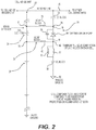
- FIG. 2 illustrates a cell sense unit of the battery cell monitoring system of FIG. 1 according to aspects of the disclosure
- FIGS. 3 and 4 illustrate a method of operating the battery cell monitoring system of FIGS. 1 and 2 according to aspects of the disclosure.
- the present disclosure relates to a battery cell monitoring system of the type well-suited for use in many applications.
- the battery cell monitoring system and associated methods of operation of this disclosure will be described in conjunction with one or more example embodiments.
- the specific example embodiments disclosed are merely provided to describe the inventive concepts, features, advantages and objectives with sufficient clarity to permit those skilled in this art to understand and practice the disclosure.
- the example embodiments are provided so that this disclosure will be thorough, and will fully convey the scope to those who are skilled in the art. Numerous specific details are set forth such as examples of specific components, devices, and methods, to provide a thorough understanding of embodiments of the present disclosure.
- a battery cell monitoring system 20 for a battery 22 having a plurality of battery cells 24 is shown in FIGS. 1 and 2 .
- the battery cell monitoring system 20 includes a radio frequency (RF) sense line or sense line 26 .
- RF radio frequency
- a plurality of cell sense units 28 each include a tank circuit 30 that has a center frequency and is electrically connected to the sense line 26 .
- the tank circuit 30 includes a positive battery node 32 for coupling to a positive terminal of one of the plurality of battery cells 24 and a negative battery node 34 for coupling to a negative terminal of the one of the plurality of battery cells 24 .
- the tank circuit 30 also includes a positive sense node 36 and a first inductor 38 having a first inductance electrically connected between the positive terminal of the battery 22 and the positive sense node 36 for blocking alternating current and radio frequency signals.
- the tank circuit 30 further includes a negative sense node 40 and a second inductor 42 having a second inductance electrically connected between the negative terminal of the battery 22 and the negative sense node 40 for blocking alternating current and radio frequency signals.
- the tank circuit 30 also includes a varactor 44 or voltage-variable capacitor electrically connected across the negative sense node 40 and the positive sense node 36 .
- the varactor 44 has a varactor anode 46 electrically connected to the negative sense node 40 and a varactor cathode 48 electrically connected to the positive sense node 36 .
- the varactor 44 is arranged in parallel with the battery cell 24 for providing a variable varactor capacitance dependent upon a cell voltage, for example, of the one of the plurality of battery cells 24 (e.g., varies as a function of the cell voltage). Other arrangements of the varactor 44 are also possible.
- the tank circuit 30 additionally includes a parallel capacitor 50 electrically connected between the varactor anode 46 and the varactor cathode 48 in parallel with the varactor 44 . So, the tank circuit 30 has a resonant or center frequency dependent on a cell parameter of interest (e.g., cell voltage of the battery cell 24 to which each of the plurality of cell sense units 28 is connected).
- a cell parameter of interest e.g., cell voltage of the battery cell 24 to which each of the plurality of cell sense units 28 is connected.
- the resonant frequency of the tank circuit 30 is a function of the fixed inductor (L) and capacitor (C) components (e.g., the first inductor 38 and the second inductor 42 and the parallel capacitor 50 ) and the variable varactor capacitance of the varactor 44 .
- L fixed inductor
- C capacitor
- the resonant frequency of the tank circuit 30 changes due to the change of the variable varactor capacitance of the varactor 44 .
- Each of the plurality of cell sense units 28 used in a multi-cell battery system (e.g., battery 22 ) is tuned to a different or unique nominal center frequency by varying the value of the inductors 38 , 42 , 52 and/or capacitors 50 , 54 , 56 .
- the plurality of cell sense units 28 also each include a first blocking capacitor 54 having a first blocking capacitance electrically connected between the positive sense node 36 and the sense line 26 for blocking direct current from the battery 22 .
- a pair of inline inductors 52 each having an inline inductance are also connected in parallel with one another and are electrically connected to the negative sense node 40 .
- the plurality of cell sense units 28 each include a second blocking capacitor 56 having a second blocking capacitance electrically connected between the pair of inline inductors 52 and an analog ground 58 for blocking direct current from the battery 22 .
- each cell sense unit 28 can be implemented in a number of ways.
- discrete components e.g., inductors 38 , 42 , 52 and capacitors 50 , 54 , 56
- the cell sense unit 28 can thus include inductance and capacitance values from the discrete components, the circuit board or cell “parasitic” inductance and capacitance, or a combination of both.
- inductors 38 , 42 , 52 and capacitors 50 , 54 , 56 may be integrated on a single chip, for instance.
- the cell sense unit 28 can instead or additionally include a discrete or integrated circuit with active components to create a marginal oscillator responsive to cell parameters or a discrete or integrated circuit with active components to buffer read-line radio frequencies into or out of the cell sense unit 28 .
- Existing structures in the battery cell 24 may also be used as part of the resonant circuit (i.e., tank circuit 30 ). Sensing multiple cell parameters may additionally be done simultaneously by using an RLC circuit and independently varying the R, L and C responsive to cell parameters.
- a cell sense reader unit 60 is electrically coupled to the sense line 26 and includes a variable frequency radio frequency generator 62 for outputting a radio frequency signal having a signal frequency that is variable to the plurality of cell sense units 28 (e.g., through the sense line 26 ).
- the disclosed battery cell monitoring system 20 utilizes bounded media (i.e., wiring) to create a radio frequency connection between the cell sense reader unit 60 and the plurality of cell sense units 28 .
- bounded media i.e., wiring
- unbounded media i.e., wireless
- the cell sense reader unit 60 is also configured to measure an impedance of the sense line 26 as the signal frequency varies and determine the center frequency of each of the plurality of cell sense units 28 .
- the cell sense reader unit 60 consists of the variable frequency radio frequency generator 62 feeding the sense line 26 , and an impedance measuring unit 64 for reading the impedance of the sense line 26 .
- the cell sense reader unit 60 sweeps the frequency of the variable frequency radio frequency generator 62 and measures the impedance of the sense line 26 during the sweep operation.
- the impedance varies with frequency as the different cell sense units 28 connected to the sense line 26 respond (e.g., resonate) to the radio frequency sweep signal.
- the resulting impedance measurement during the radio frequency sweep indicates the center frequency of each cell sense unit 28 connected to the sense line 26 .
- a multiplicity of cell parameter transducers i.e., the cell sense units 28
- a single analog to digital converter i.e., the cell sense reader unit 60 . This forms the overall battery cell monitoring system 20 with multiple transducers and few converters.
- the cell sense reader unit 60 is configured to determine a cell voltage of each of the plurality of battery cells 24 respectively electrically connected to one of the plurality of cell sense units 28 based on the center frequency determined. Specifically, by analysis of the center frequency of each cell sense unit 28 , the cell voltage of each battery cell 24 in the battery 22 can be determined due to the shift in center frequency caused by the variable varactor capacitance of the varactor 44 driven by the cell voltage. The result of this analysis can be communicated digitally for use by battery monitoring and control algorithms.
- the cell sense reader unit 60 can be implemented in a number of ways.
- the cell sense reader unit 60 can be implemented using a microcontroller with analog inputs and outputs, which are used to generate the radio frequency signal and read the impedance of the sense line 26 .
- the cell sense reader unit 60 can use a swept sine wave to identify the center frequency of each cell sense unit 28 , for example.
- the cell sense reader unit 60 can use a pseudo-random noise signal and a frequency analysis method to identify the overall frequency response of the impedance of the sense line 26 or an impulse signal and an impulse response analysis to identify the overall frequency response of the sense line 26 .
- the cell sense reader unit 60 can also sense multiple cell parameters by using a complex impedance measurement to identify R, L, and C values in each cell sense unit 28 .
- cell current or cell temperature can be measured by using circuit elements sensitive to current or temperature connected to form the tank circuit 30 with a varying resonant frequency.
- cell current can be sensed by using a connected hall-effect sensor to produce a varying voltage responsive to the magnetic field associated with the cell current flow.
- the hall voltage can, in turn, vary the capacitance of a varactor 44 in the tank circuit 30 .
- the battery cell monitoring system 20 could also be implemented by reading cell voltage using a digital circuit (not shown) that is activated by a digital code from cell sense reader unit 60 .
- This digital circuit responds to that activation by measuring and transmitting cell parameters of interest.
- the digital circuit may contain an analog to digital converter to determine cell voltage for transmission or may contain an analog means of measuring and transmitting cell voltage. This could be a voltage controlled oscillator that is turned on when the digital code is received.
- a method of operating a battery cell monitoring system 20 includes the step of 100 outputting a radio frequency signal having a signal frequency being variable to a plurality of cell sense units 28 through a sense line 26 using a variable frequency radio frequency generator 62 of a cell sense reader unit 60 .
- the method proceeds by 102 varying the signal frequency of the radio frequency signal with the variable frequency radio frequency generator 62 .
- the method continues with the step of 104 varying a variable varactor capacitance of a varactor 44 of a tank circuit 30 of each of the plurality of cell sense units 28 electrically connected to one of a plurality of battery cells 24 based on a cell parameter of interest (e.g., cell voltage) of each of the plurality of battery cells 24 .
- the next step of the method is 106 varying a center frequency of each tank circuit 30 including at least one inductor 38 , 42 connected in series with the one of the plurality of battery cells 24 between the varactor 44 and the one of the plurality of battery cells 24 in response to varying the variable varactor capacitance.
- the method proceeds with the step of 108 measuring an impedance of the sense line 26 coupled to the plurality of cell sense units 28 as the signal frequency varies using the cell sense reader unit 60 .
- the method could also include the step of measuring a complex impedance to sense multiple cell parameters of interest of the one of the plurality of battery cells 24 by identifying at least one of a resistance and an inductance and a capacitance of each of said plurality of cell sense units 28 using the cell sense reader unit 60 .
- 110 determining the center frequency of the tank circuit 30 of each of the plurality of cell sense units 28 using a cell sense reader unit 60 electrically coupled to the plurality of cell sense units 28 through a sense line 28 .
- the method concludes with the step of 112 determining the parameter of interest (e.g., cell voltage) of each of the plurality of battery cells 24 based on the center frequency of the tank circuit 30 of each of the plurality of cell sense units 28 determined using the cell sense reader unit 60 .
- the parameter of interest e.g., cell voltage
- Example embodiments are provided so that this disclosure will be thorough, and will fully convey the scope to those who are skilled in the art. Numerous specific details are set forth such as examples of specific components, devices, and methods, to provide a thorough understanding of embodiments of the present disclosure. It will be apparent to those skilled in the art that specific details need not be employed, that example embodiments may be embodied in many different forms and that neither should be construed to limit the scope of the disclosure. In some example embodiments, well-known processes, well-known device structures, and well-known technologies are not described in detail.
- first, second, third, etc. may be used herein to describe various elements, components, regions, layers and/or sections, these elements, components, regions, layers and/or sections should not be limited by these terms. These terms may be only used to distinguish one element, component, region, layer or section from another region, layer or section. Terms such as “first,” “second,” and other numerical terms when used herein do not imply a sequence or order unless clearly indicated by the context. Thus, a first element, component, region, layer or section discussed below could be termed a second element, component, region, layer or section without departing from the teachings of the example embodiments.
Abstract
Description
Claims (20)
Priority Applications (4)
| Application Number | Priority Date | Filing Date | Title |
|---|---|---|---|
| US16/159,958 US11223074B2 (en) | 2017-10-16 | 2018-10-15 | Battery cell monitoring system |
| DE112018004554.4T DE112018004554T5 (en) | 2017-10-16 | 2018-10-16 | Battery cell monitoring system |
| PCT/US2018/055980 WO2019079226A1 (en) | 2017-10-16 | 2018-10-16 | Battery cell monitoring system |
| CN201880066947.9A CN111213063A (en) | 2017-10-16 | 2018-10-16 | Battery monomer monitoring system |
Applications Claiming Priority (2)
| Application Number | Priority Date | Filing Date | Title |
|---|---|---|---|
| US201762572654P | 2017-10-16 | 2017-10-16 | |
| US16/159,958 US11223074B2 (en) | 2017-10-16 | 2018-10-15 | Battery cell monitoring system |
Publications (2)
| Publication Number | Publication Date |
|---|---|
| US20190115635A1 US20190115635A1 (en) | 2019-04-18 |
| US11223074B2 true US11223074B2 (en) | 2022-01-11 |
Family
ID=66097613
Family Applications (1)
| Application Number | Title | Priority Date | Filing Date |
|---|---|---|---|
| US16/159,958 Active 2040-05-11 US11223074B2 (en) | 2017-10-16 | 2018-10-15 | Battery cell monitoring system |
Country Status (4)
| Country | Link |
|---|---|
| US (1) | US11223074B2 (en) |
| CN (1) | CN111213063A (en) |
| DE (1) | DE112018004554T5 (en) |
| WO (1) | WO2019079226A1 (en) |
Citations (29)
| Publication number | Priority date | Publication date | Assignee | Title |
|---|---|---|---|---|
| US3559106A (en) * | 1967-07-17 | 1971-01-26 | Conductron Corp | Modulator that develops and reinforces one sideband while developing and attenuating a second sideband |
| JPH06233473A (en) | 1993-01-28 | 1994-08-19 | Toyo Commun Equip Co Ltd | Voltage detector for switching type charging circuit |
| JPH06233474A (en) | 1993-02-01 | 1994-08-19 | Toyo Commun Equip Co Ltd | Voltage detector for switching type charging circuit |
| US5546003A (en) | 1994-03-07 | 1996-08-13 | Polytronics Engineering Ltd. | Multi-cell battery monitoring system with single sensor wire |
| WO2002095897A2 (en) | 2001-05-22 | 2002-11-28 | Honeywell International Inc. | Circuit for monitoring cells of a multi-cell battery during charge |
| JP2004157077A (en) | 2002-11-08 | 2004-06-03 | Sanyo Electric Co Ltd | Method and apparatus for detecting battery voltage |
| US20060139008A1 (en) | 2004-11-29 | 2006-06-29 | Park Tae H | Protective circuit of battery pack |
| US20070108992A1 (en) | 2005-10-12 | 2007-05-17 | Hioki Denki Kabushiki Kaisha | Voltage measuring apparatus and power measuring apparatus |
| US20090058370A1 (en) * | 2007-08-28 | 2009-03-05 | Lenovo (Singapore) Pte. Ltd. | Battery pack and charging method |
| US7593822B2 (en) | 2005-05-06 | 2009-09-22 | Stragent, Llc | Battery monitor |
| US7598709B2 (en) * | 2005-09-30 | 2009-10-06 | International Components Corporation | Rapid charge lithium ion battery charger |
| US20100060295A1 (en) | 2008-09-09 | 2010-03-11 | Yazaki Corporation | Voltage detection apparatus |
| US20100090540A1 (en) | 2008-09-03 | 2010-04-15 | Texas Instruments Incorporated | Voltage sensing device |
| US20110074431A1 (en) | 2009-12-29 | 2011-03-31 | Guoxing Li | Circuits and methods for measuring cell voltages in battery packs |
| US20110273023A1 (en) | 2008-12-09 | 2011-11-10 | Mitsubishi Heavy Industries, Ltd. | Battery apparatus |
| EP2413152A1 (en) | 2009-03-25 | 2012-02-01 | Kabushiki Kaisha Toshiba | Secondary battery device and vehicle |
| US20130026994A1 (en) | 2011-07-27 | 2013-01-31 | Kabushiki Kaisha Toshiba | Battery cell monitoring circuit, battery cell module, automobile with battery cell module |
| US20130229156A1 (en) | 2010-08-27 | 2013-09-05 | Imperial Innovations Limited | Battery monitoring in electric vehicles, hybrid electric vehicles and other applications |
| US8581547B2 (en) | 2008-03-31 | 2013-11-12 | A123 Systems Llc | Method for detecting cell state-of-charge and state-of-discharge divergence of a series string of batteries or capacitors |
| US20130300426A1 (en) | 2010-09-14 | 2013-11-14 | Samsung Sdi Co Ltd | Battery system with cell voltage detecting units |
| US20140159735A1 (en) | 2011-06-10 | 2014-06-12 | Commissariat A L'energie Atomique Et Au Energies Alternatives | Device for monitoring the voltage output by the cells of an electrochemical generator |
| WO2014156263A1 (en) | 2013-03-29 | 2014-10-02 | 日立オートモティブシステムズ株式会社 | Battery system |
| US20140368209A1 (en) | 2011-11-18 | 2014-12-18 | Robert Bosch Gmbh | Method for Monitoring a Battery |
| US9261568B2 (en) | 2011-02-07 | 2016-02-16 | Analog Devices, Inc. | Diagnostic method to monitor battery cells of safety-critical systems |
| US9316694B2 (en) | 2013-02-12 | 2016-04-19 | Johnson Controls Technology Company | Battery monitoring system with time-based diagnostic activation |
| EP3037830A1 (en) | 2013-08-23 | 2016-06-29 | Hitachi Automotive Systems, Ltd. | Battery monitoring device |
| US9448287B2 (en) | 2011-07-29 | 2016-09-20 | Yokogawa Electric Corporation | Battery monitoring device |
| WO2017155272A1 (en) | 2016-03-08 | 2017-09-14 | 에스케이이노베이션 주식회사 | Battery overcharging prevention device and battery overcharging prevention method using same |
| US20190115636A1 (en) * | 2017-10-16 | 2019-04-18 | Neapco Intellectual Property Holdings, Llc | Battery cell monitoring system |
Family Cites Families (14)
| Publication number | Priority date | Publication date | Assignee | Title |
|---|---|---|---|---|
| US6100664A (en) * | 1999-03-31 | 2000-08-08 | Motorola Inc. | Sub-miniature high efficiency battery charger exploiting leakage inductance of wall transformer power supply, and method therefor |
| FR2871944B1 (en) * | 2004-06-16 | 2006-07-28 | Air Liquide | SYSTEM FOR MONITORING A SET OF ELECTROCHEMICAL CELLS AND DEVICE FOR REALIZING THE SAME |
| US7755500B2 (en) * | 2006-12-01 | 2010-07-13 | O2 Micro, Inc. | Battery systems with embedded cell monitors |
| CN201113932Y (en) * | 2007-08-06 | 2008-09-10 | 成都宏明电子股份有限公司 | Variable band-pass filter |
| CN201122178Y (en) * | 2007-11-23 | 2008-09-24 | 薛剑鸿 | Accumulator discharging synthetic tester |
| US9182448B2 (en) * | 2010-06-04 | 2015-11-10 | Toyota Jidosha Kabushiki Kaisha | Secondary battery, inspection apparatus and inspection method for secondary battery, and battery inspection system |
| US8648602B2 (en) * | 2011-06-01 | 2014-02-11 | Nxp B.V. | Battery impedance detection system, apparatus and method |
| JP6186892B2 (en) * | 2013-05-30 | 2017-08-30 | 株式会社豊田自動織機 | Fuel cell system mounted on vehicle |
| US20150219727A1 (en) * | 2014-02-06 | 2015-08-06 | Global Energy Innovations, Inc. | Battery Monitoring System Including Relay Test Circuit |
| CN105068014A (en) * | 2015-08-28 | 2015-11-18 | 江苏大学 | Parallel single cell performance monitoring system and monitoring method |
| US10330732B2 (en) * | 2015-10-01 | 2019-06-25 | California Institute Of Technology | Systems and methods for monitoring characteristics of energy units |
| CN205232171U (en) * | 2015-12-01 | 2016-05-11 | 陕西烽火实业有限公司 | Electronic tuning wave filter and terminal equipment |
| CN105954592B (en) * | 2016-07-18 | 2017-08-25 | 天津金星奥宇科技有限公司 | A kind of power battery pack internal resistance measurement system |
| CN106093583B (en) * | 2016-07-26 | 2018-10-26 | 同济大学 | A kind of Vehicular accumulator cell group battery cell impedance measurement device and method |
-
2018
- 2018-10-15 US US16/159,958 patent/US11223074B2/en active Active
- 2018-10-16 DE DE112018004554.4T patent/DE112018004554T5/en active Pending
- 2018-10-16 CN CN201880066947.9A patent/CN111213063A/en active Pending
- 2018-10-16 WO PCT/US2018/055980 patent/WO2019079226A1/en active Application Filing
Patent Citations (31)
| Publication number | Priority date | Publication date | Assignee | Title |
|---|---|---|---|---|
| US3559106A (en) * | 1967-07-17 | 1971-01-26 | Conductron Corp | Modulator that develops and reinforces one sideband while developing and attenuating a second sideband |
| JPH06233473A (en) | 1993-01-28 | 1994-08-19 | Toyo Commun Equip Co Ltd | Voltage detector for switching type charging circuit |
| JPH06233474A (en) | 1993-02-01 | 1994-08-19 | Toyo Commun Equip Co Ltd | Voltage detector for switching type charging circuit |
| US5546003A (en) | 1994-03-07 | 1996-08-13 | Polytronics Engineering Ltd. | Multi-cell battery monitoring system with single sensor wire |
| WO2002095897A2 (en) | 2001-05-22 | 2002-11-28 | Honeywell International Inc. | Circuit for monitoring cells of a multi-cell battery during charge |
| JP2004157077A (en) | 2002-11-08 | 2004-06-03 | Sanyo Electric Co Ltd | Method and apparatus for detecting battery voltage |
| US20060139008A1 (en) | 2004-11-29 | 2006-06-29 | Park Tae H | Protective circuit of battery pack |
| US7593822B2 (en) | 2005-05-06 | 2009-09-22 | Stragent, Llc | Battery monitor |
| US7598709B2 (en) * | 2005-09-30 | 2009-10-06 | International Components Corporation | Rapid charge lithium ion battery charger |
| US20070108992A1 (en) | 2005-10-12 | 2007-05-17 | Hioki Denki Kabushiki Kaisha | Voltage measuring apparatus and power measuring apparatus |
| US20090058370A1 (en) * | 2007-08-28 | 2009-03-05 | Lenovo (Singapore) Pte. Ltd. | Battery pack and charging method |
| US8581547B2 (en) | 2008-03-31 | 2013-11-12 | A123 Systems Llc | Method for detecting cell state-of-charge and state-of-discharge divergence of a series string of batteries or capacitors |
| US20100090540A1 (en) | 2008-09-03 | 2010-04-15 | Texas Instruments Incorporated | Voltage sensing device |
| US20100060295A1 (en) | 2008-09-09 | 2010-03-11 | Yazaki Corporation | Voltage detection apparatus |
| US20110273023A1 (en) | 2008-12-09 | 2011-11-10 | Mitsubishi Heavy Industries, Ltd. | Battery apparatus |
| EP2413152A1 (en) | 2009-03-25 | 2012-02-01 | Kabushiki Kaisha Toshiba | Secondary battery device and vehicle |
| US20110074431A1 (en) | 2009-12-29 | 2011-03-31 | Guoxing Li | Circuits and methods for measuring cell voltages in battery packs |
| US20130229156A1 (en) | 2010-08-27 | 2013-09-05 | Imperial Innovations Limited | Battery monitoring in electric vehicles, hybrid electric vehicles and other applications |
| US20130300426A1 (en) | 2010-09-14 | 2013-11-14 | Samsung Sdi Co Ltd | Battery system with cell voltage detecting units |
| US9261568B2 (en) | 2011-02-07 | 2016-02-16 | Analog Devices, Inc. | Diagnostic method to monitor battery cells of safety-critical systems |
| US9213067B2 (en) | 2011-06-10 | 2015-12-15 | Commissariat A L'energie Atomique Et Aux Energies Alternatives | Device for monitoring the voltage output by the cells of an electrochemical generator |
| US20140159735A1 (en) | 2011-06-10 | 2014-06-12 | Commissariat A L'energie Atomique Et Au Energies Alternatives | Device for monitoring the voltage output by the cells of an electrochemical generator |
| US20130026994A1 (en) | 2011-07-27 | 2013-01-31 | Kabushiki Kaisha Toshiba | Battery cell monitoring circuit, battery cell module, automobile with battery cell module |
| US9448287B2 (en) | 2011-07-29 | 2016-09-20 | Yokogawa Electric Corporation | Battery monitoring device |
| US20140368209A1 (en) | 2011-11-18 | 2014-12-18 | Robert Bosch Gmbh | Method for Monitoring a Battery |
| US9316694B2 (en) | 2013-02-12 | 2016-04-19 | Johnson Controls Technology Company | Battery monitoring system with time-based diagnostic activation |
| WO2014156263A1 (en) | 2013-03-29 | 2014-10-02 | 日立オートモティブシステムズ株式会社 | Battery system |
| EP3037830A1 (en) | 2013-08-23 | 2016-06-29 | Hitachi Automotive Systems, Ltd. | Battery monitoring device |
| US20160226276A1 (en) * | 2013-08-23 | 2016-08-04 | Hitachi Automotive Systems, Ltd. | Battery monitoring device |
| WO2017155272A1 (en) | 2016-03-08 | 2017-09-14 | 에스케이이노베이션 주식회사 | Battery overcharging prevention device and battery overcharging prevention method using same |
| US20190115636A1 (en) * | 2017-10-16 | 2019-04-18 | Neapco Intellectual Property Holdings, Llc | Battery cell monitoring system |
Non-Patent Citations (6)
| Title |
|---|
| "Home of RF and Wireless Vendors and Resources", pp. 1-5, 2012. (Year: 2012). * |
| Definition of varactor, Electroschematics, printed Apr. 9, 2021. (Year: 2021). * |
| Inductor, Electrical and Electronic Engineering, Jan. 2013. (Year: 2013). * |
| International Search Report; PCT/US2018/055980; 6 pages; dated Feb. 6, 2019. |
| International Search Report; PCT/US2018/055982; 10 pages; dated Jan. 7, 2019. |
| Soclof, "How Circuits Work", pp. 1-3, 2008. (Year: 2008). * |
Also Published As
| Publication number | Publication date |
|---|---|
| US20190115635A1 (en) | 2019-04-18 |
| WO2019079226A1 (en) | 2019-04-25 |
| DE112018004554T5 (en) | 2020-05-28 |
| CN111213063A (en) | 2020-05-29 |
Similar Documents
| Publication | Publication Date | Title |
|---|---|---|
| AU2019229401B2 (en) | Indicator circuit decoupled from a ground plane | |
| US9024769B2 (en) | Isolation resistance measuring apparatus having fault self-diagnosing function and fault self-diagnosing method using the same | |
| US9804113B2 (en) | Soil moisture sensor | |
| CN100447822C (en) | Human body detection sensor | |
| US20110018555A1 (en) | Electrical Measuring Device, Method and Computer Program Product | |
| CN107529346A (en) | Induction power transmitter | |
| CN104220886A (en) | Device and method for measuring insulation resistance of battery | |
| KR20140044851A (en) | Device for monitoring the voltage output by the cells of an electrochemical generator | |
| WO2002099765A1 (en) | Resonance circuit | |
| WO2006065770A2 (en) | Corrosion sensor and method of monitoring corrosion | |
| CN104871459A (en) | Standing wave ratio meter for integrated antenna tuner | |
| ES2620519T3 (en) | System and method for passive measurement of a physical quantity wirelessly | |
| US20140225791A1 (en) | Method for Checking an Antenna Coil | |
| US8463200B2 (en) | Wireless communication apparatus | |
| US20080246467A1 (en) | Device For Counting the Rotations of an Object in a Referential, and Method For Controlling One Such Device | |
| KR20170069213A (en) | Methods and apparatus for testing of wireless power transmitters and systems | |
| CN105403599B (en) | Material discrimination sensing by measurement of different impedance points | |
| US11223074B2 (en) | Battery cell monitoring system | |
| JP2011028424A (en) | Rfid tag with sensor function, and rfid system using the same | |
| US11662258B2 (en) | Force sensor integrated on substrate | |
| US11327097B2 (en) | Voltage measurement through reference circuit based impedance detection | |
| US7262543B2 (en) | System and method for monitoring piezoelectric material performance | |
| US10497990B2 (en) | Measurement system for determining the state of a battery | |
| CN104301483A (en) | Mobile phone hardware state evaluation system and method | |
| Khoshakhlagh et al. | An investigation on the energy storing process in the stimulating state of the sawr sensors interrogation |
Legal Events
| Date | Code | Title | Description |
|---|---|---|---|
| FEPP | Fee payment procedure |
Free format text: ENTITY STATUS SET TO UNDISCOUNTED (ORIGINAL EVENT CODE: BIG.); ENTITY STATUS OF PATENT OWNER: LARGE ENTITY |
|
| STPP | Information on status: patent application and granting procedure in general |
Free format text: APPLICATION DISPATCHED FROM PREEXAM, NOT YET DOCKETED |
|
| STPP | Information on status: patent application and granting procedure in general |
Free format text: DOCKETED NEW CASE - READY FOR EXAMINATION |
|
| AS | Assignment |
Owner name: NEAPCO INTELLECTUAL PROPERTY HOLDINGS, LLC, MICHIGAN Free format text: ASSIGNMENT OF ASSIGNORS INTEREST;ASSIGNOR:AWARE MOBILITY, LLC;REEL/FRAME:053945/0237 Effective date: 20200909 |
|
| STPP | Information on status: patent application and granting procedure in general |
Free format text: NON FINAL ACTION MAILED |
|
| AS | Assignment |
Owner name: PNC BANK, NATIONAL ASSOCIATION, MICHIGAN Free format text: SECURITY INTEREST;ASSIGNOR:NEAPCO HOLDINGS, LLC;REEL/FRAME:056180/0214 Effective date: 20210507 |
|
| STPP | Information on status: patent application and granting procedure in general |
Free format text: RESPONSE TO NON-FINAL OFFICE ACTION ENTERED AND FORWARDED TO EXAMINER |
|
| STPP | Information on status: patent application and granting procedure in general |
Free format text: FINAL REJECTION MAILED |
|
| STPP | Information on status: patent application and granting procedure in general |
Free format text: RESPONSE AFTER FINAL ACTION FORWARDED TO EXAMINER |
|
| STPP | Information on status: patent application and granting procedure in general |
Free format text: NOTICE OF ALLOWANCE MAILED -- APPLICATION RECEIVED IN OFFICE OF PUBLICATIONS |
|
| STPP | Information on status: patent application and granting procedure in general |
Free format text: PUBLICATIONS -- ISSUE FEE PAYMENT RECEIVED |
|
| STPP | Information on status: patent application and granting procedure in general |
Free format text: PUBLICATIONS -- ISSUE FEE PAYMENT VERIFIED |
|
| STCF | Information on status: patent grant |
Free format text: PATENTED CASE |