EP1760847A2 - Seitengepumpter Festkörperlaser und Pumpverfahren für einen Festkörperlaser - Google Patents
Seitengepumpter Festkörperlaser und Pumpverfahren für einen Festkörperlaser Download PDFInfo
- Publication number
- EP1760847A2 EP1760847A2 EP06118558A EP06118558A EP1760847A2 EP 1760847 A2 EP1760847 A2 EP 1760847A2 EP 06118558 A EP06118558 A EP 06118558A EP 06118558 A EP06118558 A EP 06118558A EP 1760847 A2 EP1760847 A2 EP 1760847A2
- Authority
- EP
- European Patent Office
- Prior art keywords
- pumping
- crystal
- source
- solid
- laser
- Prior art date
- Legal status (The legal status is an assumption and is not a legal conclusion. Google has not performed a legal analysis and makes no representation as to the accuracy of the status listed.)
- Withdrawn
Links
- 238000005086 pumping Methods 0.000 title claims abstract description 100
- 238000000034 method Methods 0.000 title claims abstract description 12
- 239000007787 solid Substances 0.000 title 1
- 239000013078 crystal Substances 0.000 claims abstract description 91
- 230000003750 conditioning effect Effects 0.000 claims abstract description 13
- 238000010521 absorption reaction Methods 0.000 claims abstract description 7
- 230000000694 effects Effects 0.000 claims abstract description 7
- 201000009310 astigmatism Diseases 0.000 claims abstract description 6
- 238000001816 cooling Methods 0.000 claims description 6
- 238000010330 laser marking Methods 0.000 claims description 2
- 230000001276 controlling effect Effects 0.000 description 3
- 238000000605 extraction Methods 0.000 description 2
- 239000000463 material Substances 0.000 description 2
- 238000010276 construction Methods 0.000 description 1
- 239000002184 metal Substances 0.000 description 1
- 238000012986 modification Methods 0.000 description 1
- 230000004048 modification Effects 0.000 description 1
- 230000003287 optical effect Effects 0.000 description 1
- 230000010355 oscillation Effects 0.000 description 1
- 238000009304 pastoral farming Methods 0.000 description 1
- 230000000644 propagated effect Effects 0.000 description 1
- 230000001105 regulatory effect Effects 0.000 description 1
Images


Classifications
-
- H—ELECTRICITY
- H01—ELECTRIC ELEMENTS
- H01S—DEVICES USING THE PROCESS OF LIGHT AMPLIFICATION BY STIMULATED EMISSION OF RADIATION [LASER] TO AMPLIFY OR GENERATE LIGHT; DEVICES USING STIMULATED EMISSION OF ELECTROMAGNETIC RADIATION IN WAVE RANGES OTHER THAN OPTICAL
- H01S3/00—Lasers, i.e. devices using stimulated emission of electromagnetic radiation in the infrared, visible or ultraviolet wave range
- H01S3/09—Processes or apparatus for excitation, e.g. pumping
- H01S3/091—Processes or apparatus for excitation, e.g. pumping using optical pumping
- H01S3/094—Processes or apparatus for excitation, e.g. pumping using optical pumping by coherent light
- H01S3/0941—Processes or apparatus for excitation, e.g. pumping using optical pumping by coherent light of a laser diode
-
- H—ELECTRICITY
- H01—ELECTRIC ELEMENTS
- H01S—DEVICES USING THE PROCESS OF LIGHT AMPLIFICATION BY STIMULATED EMISSION OF RADIATION [LASER] TO AMPLIFY OR GENERATE LIGHT; DEVICES USING STIMULATED EMISSION OF ELECTROMAGNETIC RADIATION IN WAVE RANGES OTHER THAN OPTICAL
- H01S3/00—Lasers, i.e. devices using stimulated emission of electromagnetic radiation in the infrared, visible or ultraviolet wave range
- H01S3/02—Constructional details
- H01S3/04—Arrangements for thermal management
- H01S3/042—Arrangements for thermal management for solid state lasers
-
- H—ELECTRICITY
- H01—ELECTRIC ELEMENTS
- H01S—DEVICES USING THE PROCESS OF LIGHT AMPLIFICATION BY STIMULATED EMISSION OF RADIATION [LASER] TO AMPLIFY OR GENERATE LIGHT; DEVICES USING STIMULATED EMISSION OF ELECTROMAGNETIC RADIATION IN WAVE RANGES OTHER THAN OPTICAL
- H01S3/00—Lasers, i.e. devices using stimulated emission of electromagnetic radiation in the infrared, visible or ultraviolet wave range
- H01S3/05—Construction or shape of optical resonators; Accommodation of active medium therein; Shape of active medium
- H01S3/06—Construction or shape of active medium
- H01S3/0602—Crystal lasers or glass lasers
- H01S3/0606—Crystal lasers or glass lasers with polygonal cross-section, e.g. slab, prism
-
- H—ELECTRICITY
- H01—ELECTRIC ELEMENTS
- H01S—DEVICES USING THE PROCESS OF LIGHT AMPLIFICATION BY STIMULATED EMISSION OF RADIATION [LASER] TO AMPLIFY OR GENERATE LIGHT; DEVICES USING STIMULATED EMISSION OF ELECTROMAGNETIC RADIATION IN WAVE RANGES OTHER THAN OPTICAL
- H01S3/00—Lasers, i.e. devices using stimulated emission of electromagnetic radiation in the infrared, visible or ultraviolet wave range
- H01S3/05—Construction or shape of optical resonators; Accommodation of active medium therein; Shape of active medium
- H01S3/06—Construction or shape of active medium
- H01S3/0619—Coatings, e.g. AR, HR, passivation layer
- H01S3/0625—Coatings on surfaces other than the end-faces
-
- H—ELECTRICITY
- H01—ELECTRIC ELEMENTS
- H01S—DEVICES USING THE PROCESS OF LIGHT AMPLIFICATION BY STIMULATED EMISSION OF RADIATION [LASER] TO AMPLIFY OR GENERATE LIGHT; DEVICES USING STIMULATED EMISSION OF ELECTROMAGNETIC RADIATION IN WAVE RANGES OTHER THAN OPTICAL
- H01S3/00—Lasers, i.e. devices using stimulated emission of electromagnetic radiation in the infrared, visible or ultraviolet wave range
- H01S3/05—Construction or shape of optical resonators; Accommodation of active medium therein; Shape of active medium
- H01S3/08—Construction or shape of optical resonators or components thereof
- H01S3/08072—Thermal lensing or thermally induced birefringence; Compensation thereof
-
- H—ELECTRICITY
- H01—ELECTRIC ELEMENTS
- H01S—DEVICES USING THE PROCESS OF LIGHT AMPLIFICATION BY STIMULATED EMISSION OF RADIATION [LASER] TO AMPLIFY OR GENERATE LIGHT; DEVICES USING STIMULATED EMISSION OF ELECTROMAGNETIC RADIATION IN WAVE RANGES OTHER THAN OPTICAL
- H01S3/00—Lasers, i.e. devices using stimulated emission of electromagnetic radiation in the infrared, visible or ultraviolet wave range
- H01S3/05—Construction or shape of optical resonators; Accommodation of active medium therein; Shape of active medium
- H01S3/08—Construction or shape of optical resonators or components thereof
- H01S3/081—Construction or shape of optical resonators or components thereof comprising three or more reflectors
- H01S3/0813—Configuration of resonator
- H01S3/0815—Configuration of resonator having 3 reflectors, e.g. V-shaped resonators
-
- H—ELECTRICITY
- H01—ELECTRIC ELEMENTS
- H01S—DEVICES USING THE PROCESS OF LIGHT AMPLIFICATION BY STIMULATED EMISSION OF RADIATION [LASER] TO AMPLIFY OR GENERATE LIGHT; DEVICES USING STIMULATED EMISSION OF ELECTROMAGNETIC RADIATION IN WAVE RANGES OTHER THAN OPTICAL
- H01S3/00—Lasers, i.e. devices using stimulated emission of electromagnetic radiation in the infrared, visible or ultraviolet wave range
- H01S3/10—Controlling the intensity, frequency, phase, polarisation or direction of the emitted radiation, e.g. switching, gating, modulating or demodulating
- H01S3/102—Controlling the intensity, frequency, phase, polarisation or direction of the emitted radiation, e.g. switching, gating, modulating or demodulating by controlling the active medium, e.g. by controlling the processes or apparatus for excitation
- H01S3/1028—Controlling the intensity, frequency, phase, polarisation or direction of the emitted radiation, e.g. switching, gating, modulating or demodulating by controlling the active medium, e.g. by controlling the processes or apparatus for excitation by controlling the temperature
-
- H—ELECTRICITY
- H01—ELECTRIC ELEMENTS
- H01S—DEVICES USING THE PROCESS OF LIGHT AMPLIFICATION BY STIMULATED EMISSION OF RADIATION [LASER] TO AMPLIFY OR GENERATE LIGHT; DEVICES USING STIMULATED EMISSION OF ELECTROMAGNETIC RADIATION IN WAVE RANGES OTHER THAN OPTICAL
- H01S3/00—Lasers, i.e. devices using stimulated emission of electromagnetic radiation in the infrared, visible or ultraviolet wave range
- H01S3/10—Controlling the intensity, frequency, phase, polarisation or direction of the emitted radiation, e.g. switching, gating, modulating or demodulating
- H01S3/11—Mode locking; Q-switching; Other giant-pulse techniques, e.g. cavity dumping
- H01S3/1123—Q-switching
- H01S3/117—Q-switching using intracavity acousto-optic devices
Definitions
- the present invention relates to a side-pumped solid-state laser source for industrial applications and a pumping process for a solid-state laser source.
- the invention relates to a solid-state laser source of neodymium-host type, comprising an active medium side-pumped by a laser diode and lenses for conditioning the pumping beam using a cavity layout for which the oscillating mode undergoes total reflection within the active crystal on the face struck by the pumping beam.
- a solid-state laser source with a diode side-pumping system consists of a crystal (as active medium) of circular section (rod) or rectangular section (slab), in which the oscillating mode is propagated in a longitudinal direction, passing through the crystal centre.
- the pumping beam strikes the crystal in a direction perpendicular to the propagation direction of the oscillating mode within the cavity and originates from at least one laser diode positioned to the side of the crystal.
- Another problem is the poor optimisation of the spatial superposing (matching) between the pumping beam and the fundamental oscillating mode within the cavity, which negatively influences the spatial quality of the generated laser beam.
- the temperature profile is virtually defined by the characteristics of the active medium and in particular by the absorption coefficient related to the working wavelength. If the crystal is pumped (i.e. struck by the pumping beam) asymmetrically on only one side, with homogeneous distribution of the pumping beam along the z axis and the opposite side is left free, the temperature profile along the x axis is strongly asymmetric, as the pumped side is extremely hot and the opposite side is cold. Consequently, the thermal focal length along the x axis is strongly asymmetric. In contrast, along the y axis the temperature is clearly very high at the centre of the crystal and low at the edges, along the cooled faces, so that the temperature profile is symmetrical and the thermal focal length behaves as a cylindrical lens.
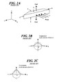
- a cavity scheme has been introduced in which the active medium is a crystal of the type shown in Figure 2A; the two opposing side faces 3 and 4 are cut at an angle greater than 0°, so that the oscillating mode which propagates along the z axis is refracted at the crystal entry, undergoes total reflection relative to the x axis at the face on which the pumping beam 1 strikes, and is again refracted at the crystal exit.
- the crystal is again pumped through a single side face, hence the temperature profile remains asymmetric along the x axis, but the internal reflection causes spatial inversion of the beam such that the thermal focal length seen on average by the beam along the x axis is symmetrical.
- the thermal focal length is symmetric both along the x axis and along the y axis, but with generally a different focal power in the two directions, as shown in Figures 2B and 2C.
- the technical aim of the present invention is therefore to provide a side-pumped solid-state laser source for industrial applications and a pumping process for a solid-state laser source by which the stated problems of the known art are eliminated.
- an object of the invention is to provide a solid-state laser source presenting a thermal focal length which is substantially equal in the two x and y directions, and a spatial quality which is substantially symmetrical in the same directions.
- Another object of the invention is to provide a laser source which is optimised, compact and economical.
- the vertical dimension of the pumping spot is regulated by possibly inserting a cylindrical lens with focal power along the y axis between the pumping laser diode and the active medium, such that the relationship between the vertical dimension of the pumping spot and the vertical dimension of the crystal generates a temperature profile of a pattern comparable to that in the x direction, as shown in Figures 4B, 4C.
- active temperature control of the cooled crystal faces has been introduced using a Peltier cell, in order to symmetrize the thermal focal length.
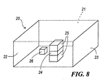
- the laser source 20 comprises a resonant cavity 21 defined by at least two spaced-apart mirrors 22, 23, an active medium of laser crystal type 24 positioned in the resonant cavity, means 25 for actively controlling the temperature of the laser crystal 24, and a Q-switch 26 positioned in the resonant cavity 21 between the laser crystal 24 and one of the two mirrors (the mirror 22 in the illustrated embodiment).
- the laser source 20 also comprises a laser diode pumping source.
- the cavity layout (this expression meaning the crystal together with the mirrors defining the cavity) and the lenses for conditioning the pumping beam are arranged to cause spatial inversion of the oscillating mode within the active medium in the absorption direction of the pumping beam, such as to symmetrize the thermal focal length seen by the mode.
- the laser source of the invention comprises lenses for conditioning the pumping beam emitted by the pumping source, to form on the side face of the laser crystal a pumping spot for symmetrizing the spatial quality of the emitted laser beam, in order to correct its undesired astigmatism effects.
- At least one of the two mirrors is partially reflecting to allow emission of the laser beam
- the active medium or crystal being a Nd-host crystal presenting a first side face 1 to be struck by the pumping beam, a second side face 2 opposite the first, an upper face 5, a lower face 6 opposite the upper face, and two side faces 3, 4 perpendicular to upper face 5 and lower face 6 and inclined to form an obtuse angle with the first side face 1.
- the active control means 25 for the laser crystal temperature are a Peltier cell arranged to cool the laser crystal via the upper face 5 and lower face 6, such that the temperature of said faces can be maintained equal and can be controlled.
- the Q-switch 26 consists of an acoustic-optical modulator or, in a different embodiment, is an electro-optical modulator or, in a different embodiment, is of passive type, while the pumping source consists of an array of laser diodes operating in continuous regime.
- the lenses conditioning the pumping beam comprise a cylindrical microlens mounted in proximity to the diode emitters, in order to collimate or reduce the divergence of the pumping beam along the fast axis.
- the conditioning lenses comprise at least one cylindrical lens with focal power along the slow axis of the laser diode, such as to intercept the pumping beam emitted by said laser diode and create on the side face of the crystal an image of suitable dimension in the direction of the slow axis.
- the conditioning lenses comprise a further cylindrical lens with focal power along the laser diode fast axis, in order to intercept the pumping beam emitted by said laser diode and create on the side face of the crystal an image of suitable dimension in the direction of the fast axis.
- the source also comprises a system for moving the cylindrical lens along the pumping beam propagation axis.
- the spatial quality of the generated laser beam is suitably controlled by acting on the dimension of the pumping spot created on the side face of the crystal along the two directions perpendicular to the direction of propagation of the pumping beam and parallel to the crystal axes.
- the solid-state laser source utilizes the principle of beam inversion within the space struck by the pumping beam to symmetrize the thermal focal length seen by the oscillating mode in the cavity, and in which a very effective system is used to carefully correct the astigmatism typical of a side-pumping scheme and to control and symmetrize the spatial quality of the generated laser beam.
- the cavity layout is of the type shown schematically in Figure 3, in which the active medium 4 is a Nd:YV04 crystal of the type shown in Figure 5, the side faces 12 and 13 being cut at an angle ⁇ >0° to the x axis and form an obtuse angle with the face 10 struck by the pumping beam.
- the laser beam oscillating in the cavity strikes the side faces 12 and 13, is refracted into the crystal in accordance with normal optical rules because of the inclination of said faces and undergoes total reflection relative to the x axis on the face 10, on which it strikes with an angle of grazing incidence of a few degrees, determined by the crystal geometry and characteristics and by the angle of incidence of the beam.
- the crystal is side-pumped by a laser diode source via the face 10 and cooled symmetrically via the faces 14 and 15, while the face 11 is left free.
- the thermal focal length seen by the oscillating mode can be controlled and symmetrized in the two x and y directions, both by controlling the vertical dimension of the pumping spot relative to the vertical dimension of the active crystal and by actively controlling the cooling temperature of the faces 14 and 15, and the spatial quality of the generated laser beam can be controlled and symmetrized by acting on the horizontal dimension, along z, of the pumping spot which forms on the crystal side face 10.
- the cavity is of symmetrical type, of total length 125 millimetres and bounded by two flat mirrors.
- the active crystal is positioned at the cavity centre, an acusto-optical Q-switch 7 being mounted in a suitable position along the arm which terminates with the exit connecter 6.
- the active medium ( Figures 5-6) is a 1.1 % Nd-doped Nd:YV04 crystal of dimensions 12x4x3mm along the z, x and y axes respectively.
- the side faces 12, 13 are cut at an angle of about 6° to the x axis, to prevent triggering of spurious oscillations in the cavity.
- the face 10 is struck by the pumping beam originating from a laser diode source 1 suitably treated by the conditioning lenses 2 and 3.
- the lens 2 is a cylindrical microlens mounted in proximity to the array of laser diode emitters, at a distance such as to collimate the pumping beam along the y axis (fast axis) or to drastically reduce its divergence, while the lens 3 is a cylindrical lens with focal power along the z axis (slow axis for the laser diode), mounted at a suitable distance from the laser diode and from the face 10 of the active crystal.
- the position of the lenses 2 and 3 uniquely defines the pumping spot dimension along y and z respectively, on the crystal entry face 10.
- the crystal is cooled via the faces 14 and 15 and temperature controlled by a Peltier cell, such as to be able to actively control the cooling temperature.
- the face 11 is left free.
- the temperature profile along the x axis is substantially established by the characteristics of the chosen active medium and is asymmetric, as the crystal is pumped (and hence heated) by only a single side face, while the opposite face is left free.
- the thermal focal length induced along x is therefore asymmetric.
- the temperature profile is symmetric and defined by the ratio between the pumping spot dimension along y and the crystal dimension along the same axis, and by the cooling temperature of the faces 14 and 15. In this case, the thermal focal length induced along y is symmetrical.
- the laser mode oscillating in the cavity strikes the crystal side faces 12 and 13 with an angle ⁇ of about 20° to the z axis, is refracted into the active medium and strikes the face 10 at an angle ⁇ of about 7°. On the same face 10 it undergoes total reflection relative to the x axis and hence a spatial inversion, which enables the temperature profile perceived by the beam to be symmetrized.
- the thermal focal length seen by the laser mode is symmetrical both along x and along y, but in general has different focal power in the two directions.
- the generated laser beam presents an astigmatic spatial profile and, in general, a different spatial quality in the two directions.
- the temperature profile along y can hence be made to have a pattern similar to that along x either by acting on the vertical dimension of the pumping spot, by fine adjustment of the position of the microlens 2 along the x axis, or by inserting a cylindrical lens with focal power along the y axis between the laser diode and the active medium, either located in a suitable position or having its position adjustable by a dedicated movement system, or by acting on the temperature of the cooled faces, by adjusting the working point of the thermoelectric (Peltier) cell which controls the temperature of the crystal faces 14 and 15 such that the thermal focal length seen by the oscillating mode in the cavity has the same focal power along the two axes.
- thermoelectric Peltier
- the following is to be considered: having fixed the cavity length and defined the value of the thermal focal length, the dimension of the fundamental mode within the crystal is uniquely determined and, as a first approximation, the beam spatial quality is defined by the ratio of the dimension of the oscillating mode within the active medium to the dimension of the pumping spot transverse to it.
- the beam spatial quality is defined once the vertical dimension of the pumping spot has been fixed, which can be optimised, as stated, by finely adjusting the position of the cylindrical microlens 2 positioned in proximity to the emitters of the laser diode 1 or by inserting between the laser diode and the crystal a cylindrical lens with focal power along the y axis, either located in a suitable position or of which the position can be adjusted by a dedicated movement system.
- the horizontal dimension of the pumping spot on the crystal face 10 can be modified, hence as can its relationship to the fundamental mode dimension, in such a manner as to symmetrize and optimise the spatial quality of the generated laser beam along the two perpendicular directions x' and y.
- a laser source with polarized beam along the y axis having a mean power of the order of 10W and a spatial quality factor M2 symmetrical in x and y and less than 2, operating in the Q-switch regime with a repetition frequency from 20 kHz to values exceeding 100 kHz and pulse time duration from 10ns to about 25ns.
- the system is air-cooled, extremely compact and simple to assemble while using largely commercial components, hence facilitating availability and maintaining a low construction cost.
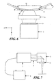
- the source can then be assembled into a marking laser source of the type shown schematically in Figure 7.
- a beam expander system 2 of magnification factor such as to adjust the beam diameter (1/e2) to about 5-6 mm and a galvanic mirror scanning head 3 with a beam focusing system in the form of a focusing flat field lens 4.
- the pumping diode control electronics the temperature controller for the diode and crystal and the acusto-optical Q-switch driver, the power unit being remotely located in a dedicated power module 5.
- the present invention also relates to a pumping process for a solid-state laser source.
- the process consists of generating on the side face of a laser crystal a pumping spot able to symmetrize the spatial quality of the emitted laser beam, such as to correct its undesired astigmatism effects.
- the process consists of striking with the pumping beam a laser crystal provided with inclined side faces forming an obtuse angle to a first entry face of the pumping beam within the same crystal, in which the oscillating mode in the cavity strikes one of the inclined side faces of the crystal, is refracted into the crystal, strikes the first face struck by the pumping beam at an angle such as to undergo total reflection at said first face about the pumping beam absorption direction together with consequent spatial inversion, and is refracted out of the crystal at the second inclined face.
- the temperature pattern within the crystal and consequently the thermal focal length in the cooling direction are defined by the relationship between the dimension of the pumping spot created on the crystal side face in the same direction and the physical dimension of the crystal itself, and by the cooling temperature to which the upper and lower crystal faces are lowered.
- the pumping source of continuous type can also consist (in addition to a laser diode or an array of laser diodes) of a stack of laser diodes operating under continuous regime.
- the pumping source can consist of a source operating under quasi-continuous (quasi-CW or QCW) regime, in which case the Q-switch within the cavity may or may not be provided.
- the source operating under quasi-continuous (quasi-CW or QCW) regime can consist of a laser diode array operating under quasi-continuous (quasi-CW or QCW) regime or a stack of laser diodes operating under quasi-continuous (quasi-CW or QCW) regime.
Landscapes
- Physics & Mathematics (AREA)
- Electromagnetism (AREA)
- Engineering & Computer Science (AREA)
- Plasma & Fusion (AREA)
- Optics & Photonics (AREA)
- Lasers (AREA)
Applications Claiming Priority (1)
| Application Number | Priority Date | Filing Date | Title |
|---|---|---|---|
| IT001609A ITMI20051609A1 (it) | 2005-08-29 | 2005-08-29 | Sorgente laser a stato solido pompata lateralmente e procedimento di pompaggio di una sorgente laser a stato solido |
Publications (2)
| Publication Number | Publication Date |
|---|---|
| EP1760847A2 true EP1760847A2 (de) | 2007-03-07 |
| EP1760847A3 EP1760847A3 (de) | 2009-11-25 |
Family
ID=37563249
Family Applications (1)
| Application Number | Title | Priority Date | Filing Date |
|---|---|---|---|
| EP06118558A Withdrawn EP1760847A3 (de) | 2005-08-29 | 2006-08-07 | Seitengepumpter Festkörperlaser und Pumpverfahren für einen Festkörperlaser |
Country Status (4)
| Country | Link |
|---|---|
| US (1) | US7480318B2 (de) |
| EP (1) | EP1760847A3 (de) |
| JP (1) | JP2007067396A (de) |
| IT (1) | ITMI20051609A1 (de) |
Families Citing this family (10)
| Publication number | Priority date | Publication date | Assignee | Title |
|---|---|---|---|---|
| JP2010186793A (ja) * | 2009-02-10 | 2010-08-26 | Mitsubishi Electric Corp | 固体レーザーモジュール |
| US8406267B2 (en) * | 2009-02-20 | 2013-03-26 | Massachusetts Institute Of Technology | Grazing-incidence-disk laser element |
| JP2011199181A (ja) * | 2010-03-23 | 2011-10-06 | Kataoka Seisakusho:Kk | レーザ増幅器 |
| JP5831896B2 (ja) * | 2011-02-28 | 2015-12-09 | 国立大学法人 千葉大学 | 光渦レーザービーム発振装置及び発振方法 |
| JP2016002372A (ja) * | 2014-06-18 | 2016-01-12 | キヤノン株式会社 | 被検体情報取得装置 |
| CN107946891B (zh) * | 2017-12-14 | 2019-09-17 | 湖北工业大学 | 一种大功率紫外固体激光器 |
| CN108963740B (zh) * | 2018-07-09 | 2019-08-09 | 北京空间机电研究所 | 一种板条固体激光器泵浦增益模块 |
| CN116698362B (zh) * | 2023-02-23 | 2024-08-06 | 武汉华日精密激光股份有限公司 | 端面泵浦激光晶体热透镜焦距测量方法以及装置 |
| CN116345281B (zh) * | 2023-03-01 | 2025-11-25 | 北京工业大学 | 一种混合泵浦板条激光放大器 |
| CN117595049B (zh) * | 2024-01-18 | 2024-04-05 | 长春理工大学 | 一种异形多程增益激光系统、激光器以及激光雷达 |
Family Cites Families (10)
| Publication number | Priority date | Publication date | Assignee | Title |
|---|---|---|---|---|
| US5276695A (en) * | 1992-10-26 | 1994-01-04 | The United States Of America As Represented By The Secretary Of The Navy | Multifrequency, rapidly sequenced or simultaneous tunable laser |
| US5555254A (en) * | 1993-11-05 | 1996-09-10 | Trw Inc. | High brightness solid-state laser with zig-zag amplifier |
| US5485482A (en) * | 1993-12-08 | 1996-01-16 | Selker; Mark D. | Method for design and construction of efficient, fundamental transverse mode selected, diode pumped, solid state lasers |
| US5724372A (en) * | 1995-01-20 | 1998-03-03 | Hughes Electronics | Diode-pumped laser system using uranium-doped Q-switch |
| US5909306A (en) * | 1996-02-23 | 1999-06-01 | President And Fellows Of Harvard College | Solid-state spectrally-pure linearly-polarized pulsed fiber amplifier laser system useful for ultraviolet radiation generation |
| US6002695A (en) * | 1996-05-31 | 1999-12-14 | Dpss Lasers, Inc. | High efficiency high repetition rate, intra-cavity tripled diode pumped solid state laser |
| US6212216B1 (en) * | 1996-12-17 | 2001-04-03 | Ramadas M. R. Pillai | External cavity micro laser apparatus |
| US6347101B1 (en) * | 1998-04-16 | 2002-02-12 | 3D Systems, Inc. | Laser with absorption optimized pumping of a gain medium |
| US6167069A (en) * | 1998-05-01 | 2000-12-26 | The Regents Of The University Of California | Thermal lens elimination by gradient-reduced zone coupling of optical beams |
| JP4885429B2 (ja) * | 2004-05-13 | 2012-02-29 | オリンパス株式会社 | 光刺激装置および光走査型観察装置 |
-
2005
- 2005-08-29 IT IT001609A patent/ITMI20051609A1/it unknown
-
2006
- 2006-08-07 EP EP06118558A patent/EP1760847A3/de not_active Withdrawn
- 2006-08-16 JP JP2006221780A patent/JP2007067396A/ja active Pending
- 2006-08-29 US US11/511,326 patent/US7480318B2/en active Active
Also Published As
| Publication number | Publication date |
|---|---|
| US7480318B2 (en) | 2009-01-20 |
| EP1760847A3 (de) | 2009-11-25 |
| US20070047611A1 (en) | 2007-03-01 |
| ITMI20051609A1 (it) | 2007-02-28 |
| JP2007067396A (ja) | 2007-03-15 |
Similar Documents
| Publication | Publication Date | Title |
|---|---|---|
| US9847616B1 (en) | Laser beam amplification by homogenous pumping of an amplification medium | |
| US6654163B1 (en) | Optical amplifier arrangement for a solid state laser | |
| US6999491B2 (en) | High intensity and high power solid state laser amplifying system and method | |
| JPH08250797A (ja) | 固体レーザ装置 | |
| US7480318B2 (en) | Side-pumped solid-state laser source, and pumping process for a solid-state laser source | |
| CN113423529A (zh) | 激光加工机、加工方法和激光光源 | |
| US6002695A (en) | High efficiency high repetition rate, intra-cavity tripled diode pumped solid state laser | |
| JP2016525803A (ja) | Qスイッチ固体レーザー | |
| US6865213B2 (en) | Diode-pumped solid-state laser in a polyhedronal geometry | |
| US9306365B2 (en) | Pump device for pumping an amplifying laser medium | |
| JP4990205B2 (ja) | レーザ熱処理装置 | |
| JP2000164958A (ja) | Ld励起レーザ発振方法とレーザ発振器、これによるレーザ加工装置 | |
| US6973108B2 (en) | Arrangement for pumping an anisotropic laser crystal | |
| JP2009194176A (ja) | 固体レーザ装置及びレーザ加工方法 | |
| TWI844700B (zh) | 用於雷射照射的轉換裝置及雷射裝置 | |
| KR102833274B1 (ko) | 레이저 방사선용 변환 기기 | |
| JP2023055378A (ja) | レーザ増幅器及びレーザ増幅システム | |
| JP2002134817A (ja) | Ld励起スラブ型固体レーザ発生装置 | |
| US7573930B2 (en) | Anamorphotic solid-sate laser | |
| JP3967754B2 (ja) | 側面ポンピングレーザー | |
| CN116247496A (zh) | 厄米-高斯激光束产生装置 | |
| JPH0918071A (ja) | ジグザグスラブレーザの収差制御 | |
| JPH10125991A (ja) | 固体レーザ発振器及びレーザマーキング装置 | |
| JPH03163889A (ja) | 半導体レーザ励起形固体レーザ装置 |
Legal Events
| Date | Code | Title | Description |
|---|---|---|---|
| PUAI | Public reference made under article 153(3) epc to a published international application that has entered the european phase |
Free format text: ORIGINAL CODE: 0009012 |
|
| AK | Designated contracting states |
Kind code of ref document: A2 Designated state(s): AT BE BG CH CY CZ DE DK EE ES FI FR GB GR HU IE IS IT LI LT LU LV MC NL PL PT RO SE SI SK TR |
|
| AX | Request for extension of the european patent |
Extension state: AL BA HR MK YU |
|
| PUAL | Search report despatched |
Free format text: ORIGINAL CODE: 0009013 |
|
| AK | Designated contracting states |
Kind code of ref document: A3 Designated state(s): AT BE BG CH CY CZ DE DK EE ES FI FR GB GR HU IE IS IT LI LT LU LV MC NL PL PT RO SE SI SK TR |
|
| AX | Request for extension of the european patent |
Extension state: AL BA HR MK RS |
|
| AKX | Designation fees paid | ||
| REG | Reference to a national code |
Ref country code: DE Ref legal event code: 8566 |
|
| STAA | Information on the status of an ep patent application or granted ep patent |
Free format text: STATUS: THE APPLICATION IS DEEMED TO BE WITHDRAWN |
|
| 18D | Application deemed to be withdrawn |
Effective date: 20100526 |