EP1760747A2 - Disjoncteur électrique - Google Patents
Disjoncteur électrique Download PDFInfo
- Publication number
- EP1760747A2 EP1760747A2 EP06015650A EP06015650A EP1760747A2 EP 1760747 A2 EP1760747 A2 EP 1760747A2 EP 06015650 A EP06015650 A EP 06015650A EP 06015650 A EP06015650 A EP 06015650A EP 1760747 A2 EP1760747 A2 EP 1760747A2
- Authority
- EP
- European Patent Office
- Prior art keywords
- release
- lever
- electromagnetic
- thermal
- arm
- Prior art date
- Legal status (The legal status is an assumption and is not a legal conclusion. Google has not performed a legal analysis and makes no representation as to the accuracy of the status listed.)
- Granted
Links
Images

Classifications
-
- H—ELECTRICITY
- H01—ELECTRIC ELEMENTS
- H01H—ELECTRIC SWITCHES; RELAYS; SELECTORS; EMERGENCY PROTECTIVE DEVICES
- H01H71/00—Details of the protective switches or relays covered by groups H01H73/00 - H01H83/00
- H01H71/10—Operating or release mechanisms
- H01H71/50—Manual reset mechanisms which may be also used for manual release
- H01H71/52—Manual reset mechanisms which may be also used for manual release actuated by lever
-
- H—ELECTRICITY
- H01—ELECTRIC ELEMENTS
- H01H—ELECTRIC SWITCHES; RELAYS; SELECTORS; EMERGENCY PROTECTIVE DEVICES
- H01H71/00—Details of the protective switches or relays covered by groups H01H73/00 - H01H83/00
- H01H71/10—Operating or release mechanisms
- H01H71/12—Automatic release mechanisms with or without manual release
- H01H71/40—Combined electrothermal and electromagnetic mechanisms
-
- C—CHEMISTRY; METALLURGY
- C08—ORGANIC MACROMOLECULAR COMPOUNDS; THEIR PREPARATION OR CHEMICAL WORKING-UP; COMPOSITIONS BASED THEREON
- C08L—COMPOSITIONS OF MACROMOLECULAR COMPOUNDS
- C08L2201/00—Properties
- C08L2201/12—Shape memory
-
- H—ELECTRICITY
- H01—ELECTRIC ELEMENTS
- H01H—ELECTRIC SWITCHES; RELAYS; SELECTORS; EMERGENCY PROTECTIVE DEVICES
- H01H2300/00—Orthogonal indexing scheme relating to electric switches, relays, selectors or emergency protective devices covered by H01H
- H01H2300/034—Orthogonal indexing scheme relating to electric switches, relays, selectors or emergency protective devices covered by H01H using magnetic shape memory [MSM] also an austenite-martensite transformation, but then magnetically controlled
-
- H—ELECTRICITY
- H01—ELECTRIC ELEMENTS
- H01H—ELECTRIC SWITCHES; RELAYS; SELECTORS; EMERGENCY PROTECTIVE DEVICES
- H01H71/00—Details of the protective switches or relays covered by groups H01H73/00 - H01H83/00
- H01H71/10—Operating or release mechanisms
- H01H71/12—Automatic release mechanisms with or without manual release
- H01H71/14—Electrothermal mechanisms
- H01H71/145—Electrothermal mechanisms using shape memory materials
Definitions
- the invention relates to an electrical switching device according to the preamble of claim 1.
- the invention relates to a circuit breaker used to shut down loads in the event of a short circuit or overcurrent.
- the invention can of course also be applied to motor protection switches and residual current circuit breakers.
- a circuit breaker has in its interior an electromagnetic actuator having a plunger armature electromagnet with a core and a movable armature around which a coil is wound.
- the armature moves and on the one hand strikes the contact lever, so that the contact point is opened quickly; On the other hand, it also causes a permanent opening of the contact point via a switching mechanism.
- the thermal release which is usually designed as a bimetallic release, acts on the switch lock exclusively to the permanent opening the contact point.
- the bimetal is usually designed as a strip, which bends due to the different expansion coefficients of the interconnected metals.
- a strip made of a shape memory alloy can also be used.
- the switch lock between two boards is mounted, which are interconnected and which also form the bearing point for the corresponding, forming the Verklinkungsstelle components or record.
- the electromagnetic release is located between the bimetallic strip and the contact lever.
- the object of the invention is to further improve a switch of the type mentioned, in particular to simplify the assembly considerably and to improve the sequence of movements of the components of the switching mechanism.
- the contact carrier formed as a contact lever between the thermal and the electromagnetic release;
- the latch lever forms with a rotatably mounted, cooperating with the electromagnetic release trigger the Verklinkungsstelle, wherein the thermal release is coupled by means of a contact carrier cross-rod with the release lever, so that both the thermal and the electromagnetic release in an over- and / or Short-circuit current via the release lever, open the latching point.
- release lever between the axis of rotation of the control handle and the electromagnetic release is rotatably mounted, wherein the release lever is designed as a double arm, whose first arm forms the Verklinkungsstelle together with the latch lever and the second arm cooperates with the thermal release and the electromagnetic release.
- the first lever arm of the release lever in the closed position extends approximately perpendicular to the front wall of the switching device or approximately perpendicular to the central axis of the electromagnetic release, whereas the second lever arm has a first, perpendicular to the first arm extending portion and an adjoining second portion which covers the striker of the electromagnetic actuator.
- the axis of rotation of the release lever is fixed on a line which is formed by the bearing points of the release lever and the control handle, this line is approximately perpendicular to the mounting plane or to the front wall.
- a spring arrangement which constantly acts on the release lever so that it spends the impact armature of the solenoid system at the end of a trip in its triggering ready position, whereby the Verklinkungsstelle is latched again and the switching device can be turned on again.
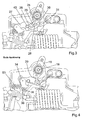
- a circuit breaker 10 which is partially visible in the area of its switching mechanism, has a housing 11, which is composed of a cup-shaped housing lower part and a cup-shaped housing upper part. In the view according to Figures 1 to 4, only the lower housing part can be seen.
- the housing is constructed in a base construction and has a front front wall 12, two rear front walls 13 and 14, which are not fully shown in the drawing, two front narrow side walls 15 and 16 which connect the front front wall 12 with the rear front walls; parallel to the front front wall or the rear front walls 13, 14 is a downwards the housing final mounting wall, which is not shown in the figures 1 to 4 and which is not relevant to the invention.
- the front front wall 12 has an approximately semicircular bulge 17, in the region of a bearing 18, a switch knob 19 is mounted.
- the switch knob 19 is a double-armed lever with a control handle 20 and a located inside the switching device eye-shaped projection 21; in the eye-shaped extension 21, a passage opening 22 is introduced; the center of the passage opening 22, the center of the bearing 18 and the center line of the control handle 20 are in line or aligned with each other.
- the switching handle 20 protrudes from an opening 23 in the bulge or protrusion 17 out.
- a leg (not shown) of a bracket 24 is inserted, which has a U-shape, wherein the web 25 of the bracket is visible in Figures 1 to 4.
- the other leg of the U-shaped bracket 24 engages in an opening 26 of a tab 27 and in a slot 28 of a ratchet lever 29 and is guided therein.
- the latch lever 29 has a latching nose 30, which with a return 31 at a hammer 32 forms a latch.
- the Verklinkungsstelle is accordingly referred to below with the reference numerals 30/31.
- the other end of the tab 27 is articulated by means of a hinge axis 33 with a contact lever 34 which has approximately centrally a slot 35 with which it is rotatably mounted on a stationary pin 36 in the housing 11.
- the contact lever 35 is a Doppelarmhebel
- the bearing 33 of the opposite lever 37 carries the so-called movable contact piece 38 which cooperates with a fixed contact piece 39.
- the latch lever 29 is rotatably mounted at its latching point 30, 31 opposite end via a pin assembly 40 in the housing (both in the lower housing part and in the upper housing part).
- the arrangement is made such that the tab 27 and the latch lever 29 are approximately in line.
- the switching mechanism In the closed position, in which the nose 30 rests against the recess 31, the switching mechanism is in the closed position, so if the movable contact piece 38 contacts the fixed contact piece 39 in a first stable position, in which the central axis of the web 25 laterally, in the embodiment of FIG. 2 on the left, next to the central axis of the bearing or the pivot bearing 18 of the switch knob 19 passes, so that the central axis of the leg 25 with the line formed by the central axis of the opening 22 and the central axis of the bearing 18 an obtuse angle occupies, which is open in the direction of Verklinkungsstelle 30/31.
- the tab 27 and the latch lever 29 are approximately parallel to the front front wall. In the closed position, the bracket 24 pushes the tab away from the latching point 30/31, so that the resulting force causes the switch-on force.
- the slot 35 lays down with its end, which on the side of the contact lever 34, on which the movable contact piece is located at. The slot 35 extends approximately perpendicular to the longitudinal extent of the contact lever 34th
- the impact lever or release lever 32 is pivotable at 18 about a fixed axis 41 below the control handle or its bearing point. He has a first lever arm 42, on which the recess 31 is formed; in the closed position of this first lever arm 42 is perpendicular or approximately perpendicular to the front wall.
- the hammer 32 further has a second lever arm 43 having a first portion 44 and a second section 45, which adjoins the first portion 44 and approximately to the attachment side, that is, away from the front side 12, projects.
- the switching device has an electromagnetic release 46, the impact armature 47 extends parallel to the front wall or to the mounting wall and the protruding from the trigger 46 end 48 is covered by the section 45.
- an end 49 of a connecting rod 50 is connected, hinged here, which by means of a pin 51 or a nose 51, which projects perpendicular to the plane in this and therefore is shown only dashed, behind a Thermobimetallst Shape 52, the thermal trigger is, attacks.
- the thermal release 52 is located between the nose 51 and the portion 45th
- the longitudinal axis of the connecting rod 50 extends approximately perpendicular to the longitudinal extent of the bimetallic strip; in the embodiment according to FIGS. 1 to 4, the longitudinal extent of the bimetallic strip 52 with the fastening side forms an acute angle, which is open towards the electromagnetic release.
- a compression spring 53 which acts on the contact lever clockwise about the bearing 36, so that the Compression spring 53, the switch-off, so that movement of the contact lever 34 from the position shown in FIG. 2 in the position shown in FIG. 1, supported.
- the switch lock described with reference to a circuit breaker can also be used in a residual current circuit breaker; In this case, instead of the electromagnetic release 46, which responds to short-circuit current, a trigger should be used which responds to a fault current.
- a contact carrier which carries a contact bridge, which in the ON state two fixed contacts, so a pair of contact pieces, electrically conductively connects.
- the section 45 which is perpendicular to the first arm 42, continues beyond its bearing point 41 into an extension 60, which has an angling, not shown in FIGS. 1 to 4, perpendicular to the plane of the drawing into the plane of the drawing projects.
- a spring 63 is wound around one arm (not shown) is held stationary in the housing and the other spring arm 64 resiliently presses against the extension 60, so that this spring the recoil lever or release lever constantly counterclockwise in the direction of pushing back the striker pin 47 and the armature 47 acted upon.
- This spring causes the hammer to be pushed into its ready-to-latch position, so that when the latch lever is moved into the open position, see above, it cooperates with the first arm 42 of the release lever to form the latching point.
Landscapes
- Physics & Mathematics (AREA)
- Electromagnetism (AREA)
- Breakers (AREA)
- Control Of Motors That Do Not Use Commutators (AREA)
- Electrical Discharge Machining, Electrochemical Machining, And Combined Machining (AREA)
- Control Of Electric Motors In General (AREA)
Applications Claiming Priority (1)
| Application Number | Priority Date | Filing Date | Title |
|---|---|---|---|
| DE102005041232A DE102005041232B4 (de) | 2005-08-31 | 2005-08-31 | Elektrisches Schaltgerät |
Publications (3)
| Publication Number | Publication Date |
|---|---|
| EP1760747A2 true EP1760747A2 (fr) | 2007-03-07 |
| EP1760747A3 EP1760747A3 (fr) | 2007-05-16 |
| EP1760747B1 EP1760747B1 (fr) | 2010-04-21 |
Family
ID=37492294
Family Applications (1)
| Application Number | Title | Priority Date | Filing Date |
|---|---|---|---|
| EP06015650A Not-in-force EP1760747B1 (fr) | 2005-08-31 | 2006-07-27 | Disjoncteur électrique |
Country Status (7)
| Country | Link |
|---|---|
| US (1) | US7504914B2 (fr) |
| EP (1) | EP1760747B1 (fr) |
| CN (1) | CN1929069B (fr) |
| AT (1) | ATE465507T1 (fr) |
| CA (1) | CA2558205A1 (fr) |
| DE (2) | DE102005041232B4 (fr) |
| PT (1) | PT1760747E (fr) |
Cited By (4)
| Publication number | Priority date | Publication date | Assignee | Title |
|---|---|---|---|---|
| GB2453861A (en) * | 2007-03-01 | 2009-04-22 | Siemens Ag | Circuit breaker |
| CN102332371A (zh) * | 2011-09-06 | 2012-01-25 | 浙江加西亚电子电器有限公司 | 小型断路器 |
| EP2608242A1 (fr) * | 2011-12-23 | 2013-06-26 | Abb Ag | Commutateur de séparation de charge électrique pour basses tensions |
| US11398363B2 (en) * | 2018-10-30 | 2022-07-26 | Eaton Intelligent Power Limited | Circuit interrupters with lockout feature and related methods |
Families Citing this family (7)
| Publication number | Priority date | Publication date | Assignee | Title |
|---|---|---|---|---|
| DE102004055564B4 (de) * | 2004-11-18 | 2022-05-05 | Abb Ag | Elektrisches Installationsschaltgerät |
| EP2608233A1 (fr) * | 2011-12-23 | 2013-06-26 | Abb Ag | Commutateur de séparation de charge électrique pour basses tensions |
| DE102014107265B4 (de) * | 2014-05-22 | 2020-01-02 | Eaton Intelligent Power Limited | Schaltgerät |
| DK3206219T3 (da) * | 2016-02-10 | 2019-08-12 | Abb Spa | Omskifterindretning til elektriske lavspændingsinstallationer |
| DE102016108292A1 (de) * | 2016-05-04 | 2017-11-09 | Abb Schweiz Ag | Elektrisches Installationsgerät mit Schaltstellungsanzeige |
| US10847333B2 (en) * | 2018-09-17 | 2020-11-24 | Siemends Industry, Inc. | Circuit breakers including dual triggering devices and methods of operating same |
| CN111969553B (zh) * | 2020-08-10 | 2022-05-10 | 润世达工程有限公司 | 一种电力用过电流保护装置 |
Citations (5)
| Publication number | Priority date | Publication date | Assignee | Title |
|---|---|---|---|---|
| DE535664C (de) * | 1931-10-14 | Voigt & Haeffner Akt Ges | UEberstromschalter mit Waerme- und Kurzschlussausloesung | |
| DD119907A5 (fr) * | 1974-05-14 | 1976-05-12 | ||
| DE2933767A1 (de) * | 1979-08-21 | 1981-03-26 | Licentia Patent-Verwaltungs-Gmbh, 60596 Frankfurt | Schaltmechanismus fuer leitungsschutzschalter |
| GB2176659A (en) * | 1985-05-01 | 1986-12-31 | Mitsubishi Electric Corp | Circuit interrupter |
| EP0710973A1 (fr) * | 1994-10-18 | 1996-05-08 | Bticino S.P.A. | Commutateur magnétothermique avec protection thermique qui peut être calibré mécaniquement et un procédé associé pour le calibrage |
Family Cites Families (19)
| Publication number | Priority date | Publication date | Assignee | Title |
|---|---|---|---|---|
| US2783330A (en) * | 1955-01-31 | 1957-02-26 | Gen Electric | Automatic circuit breaker |
| US2941058A (en) * | 1957-02-05 | 1960-06-14 | Fed Pacific Electric Co | Automatic circuit breakers |
| CH543174A (de) * | 1971-09-30 | 1973-10-15 | Carl Maier & Cie Elek Sche Sch | Leitungsschutzschalter |
| US3983454A (en) * | 1974-08-12 | 1976-09-28 | Westinghouse Electric Corporation | Distribution transformer secondary circuit breaker |
| US3950714A (en) * | 1974-09-18 | 1976-04-13 | Westinghouse Electric Corporation | Self-adjusting circuit breaker with rotating trip assembly |
| GB1525157A (en) * | 1975-08-06 | 1978-09-20 | Ellenberger & Poensgen | Multi-pole excess current circuit breaker |
| GB1492906A (en) * | 1976-01-12 | 1977-11-23 | Ottermill Ltd | Electric circuit breaker |
| US4132967A (en) * | 1976-04-29 | 1979-01-02 | I-T-E Imperial Corporation | Unitized combination starter |
| DE3339399A1 (de) * | 1983-10-29 | 1985-05-09 | Sursum Elektrizitätsgesellschaft Leyhausen GmbH & Co, 8500 Nürnberg | Selbstschalter mit lichtbogenblasfeld |
| US4625190A (en) * | 1985-03-04 | 1986-11-25 | Westinghouse Electric Corp. | Remotely controlled solenoid operated circuit breaker |
| US4636760A (en) * | 1985-04-10 | 1987-01-13 | Westinghouse Electric Corp. | Low voltage circuit breaker with remote switching function |
| US4714907A (en) * | 1985-07-31 | 1987-12-22 | Merlin Gerin | Miniature electrical circuit breaker with multiple moving contacts and thermomagnetic trip release |
| DE3602072A1 (de) * | 1986-01-24 | 1987-07-30 | Fred Stahl | Anbau, wie wintergarten, solaranbau und dgl., an ein wohnhaus |
| US4725799A (en) * | 1986-09-30 | 1988-02-16 | Westinghouse Electric Corp. | Circuit breaker with remote control |
| DE3915127C1 (fr) * | 1989-05-09 | 1990-09-06 | Flohr, Peter, Dipl.-Ing., 7790 Messkirch, De | |
| US5185590A (en) * | 1991-12-23 | 1993-02-09 | North American Philips Corporation | Magnetic blow-out circuit breaker with booster loop/arc runner |
| DE10133878B4 (de) * | 2001-07-12 | 2004-07-08 | Siemens Ag | Schaltgerät mit einem Schaltschloss |
| DE10335704A1 (de) * | 2003-08-05 | 2005-03-03 | Abb Patent Gmbh | Elektrische Auslöseeinrichtung für ein elektrisches Schaltgerät |
| CN1298003C (zh) * | 2004-05-25 | 2007-01-31 | Tcl国际电工(无锡)有限公司 | 一种小型断路器 |
-
2005
- 2005-08-31 DE DE102005041232A patent/DE102005041232B4/de not_active Expired - Fee Related
-
2006
- 2006-07-27 EP EP06015650A patent/EP1760747B1/fr not_active Not-in-force
- 2006-07-27 DE DE502006006761T patent/DE502006006761D1/de active Active
- 2006-07-27 AT AT06015650T patent/ATE465507T1/de active
- 2006-07-27 PT PT06015650T patent/PT1760747E/pt unknown
- 2006-08-30 CA CA002558205A patent/CA2558205A1/fr not_active Abandoned
- 2006-08-30 CN CN2006101266239A patent/CN1929069B/zh not_active Expired - Fee Related
- 2006-08-31 US US11/513,133 patent/US7504914B2/en not_active Expired - Fee Related
Patent Citations (5)
| Publication number | Priority date | Publication date | Assignee | Title |
|---|---|---|---|---|
| DE535664C (de) * | 1931-10-14 | Voigt & Haeffner Akt Ges | UEberstromschalter mit Waerme- und Kurzschlussausloesung | |
| DD119907A5 (fr) * | 1974-05-14 | 1976-05-12 | ||
| DE2933767A1 (de) * | 1979-08-21 | 1981-03-26 | Licentia Patent-Verwaltungs-Gmbh, 60596 Frankfurt | Schaltmechanismus fuer leitungsschutzschalter |
| GB2176659A (en) * | 1985-05-01 | 1986-12-31 | Mitsubishi Electric Corp | Circuit interrupter |
| EP0710973A1 (fr) * | 1994-10-18 | 1996-05-08 | Bticino S.P.A. | Commutateur magnétothermique avec protection thermique qui peut être calibré mécaniquement et un procédé associé pour le calibrage |
Cited By (6)
| Publication number | Priority date | Publication date | Assignee | Title |
|---|---|---|---|---|
| GB2453861A (en) * | 2007-03-01 | 2009-04-22 | Siemens Ag | Circuit breaker |
| GB2453861B (en) * | 2007-03-01 | 2009-06-03 | Siemens Ag | Circuit breaker |
| CN102332371A (zh) * | 2011-09-06 | 2012-01-25 | 浙江加西亚电子电器有限公司 | 小型断路器 |
| CN102332371B (zh) * | 2011-09-06 | 2013-11-06 | 加西亚电子电器有限公司 | 小型断路器 |
| EP2608242A1 (fr) * | 2011-12-23 | 2013-06-26 | Abb Ag | Commutateur de séparation de charge électrique pour basses tensions |
| US11398363B2 (en) * | 2018-10-30 | 2022-07-26 | Eaton Intelligent Power Limited | Circuit interrupters with lockout feature and related methods |
Also Published As
| Publication number | Publication date |
|---|---|
| DE502006006761D1 (de) | 2010-06-02 |
| ATE465507T1 (de) | 2010-05-15 |
| CN1929069B (zh) | 2012-06-06 |
| CN1929069A (zh) | 2007-03-14 |
| DE102005041232B4 (de) | 2009-11-26 |
| US20070046404A1 (en) | 2007-03-01 |
| US7504914B2 (en) | 2009-03-17 |
| EP1760747B1 (fr) | 2010-04-21 |
| PT1760747E (pt) | 2010-07-16 |
| DE102005041232A1 (de) | 2007-03-01 |
| EP1760747A3 (fr) | 2007-05-16 |
| CA2558205A1 (fr) | 2007-02-28 |
Similar Documents
| Publication | Publication Date | Title |
|---|---|---|
| EP1760747B1 (fr) | Disjoncteur électrique | |
| EP1760748B1 (fr) | Appareil de commutation électrique | |
| EP0090176B1 (fr) | Disjoncteur de surintensité | |
| EP1728260B1 (fr) | Mecanisme de commutation pour appareil de distribution d'installation electrique | |
| EP2769399B1 (fr) | Série de disjoncteurs multipolaires | |
| EP0091040B1 (fr) | Disjoncteur de protection à courant excessif | |
| DE827984C (de) | Selbstschalter | |
| DE102011018498A1 (de) | Elektrisches Installationsgerät und System umfassend ein Installationsschaltgerät und einen Hilfsschalter | |
| EP0849759B1 (fr) | Appareil de coupure pour une installation électrique | |
| DE102011008834A1 (de) | Installationsschaltgerät | |
| DE102010005345B4 (de) | Elektrisches Schaltgerät in modularer Bauweise | |
| DE102008016575A1 (de) | Voll-Schutzschalter | |
| DE102006057647A1 (de) | Installationsgerät mit einer Doppelunterbrechung | |
| EP0731979B1 (fr) | Interrupteur de securite | |
| EP0851449B1 (fr) | Appareil de commutation pour une installation électrique | |
| EP1488438B1 (fr) | Disjoncteur avec interruption bipolaire | |
| EP1659604B1 (fr) | Appareil de commutation pour une installation électrique | |
| AT404647B (de) | Elektrischer schutzschalter | |
| DE10324390A1 (de) | Elektrische Auslöseeinrichtung für einen elektrischen Schalter | |
| DE102005046640A1 (de) | Elektrisches Installationsgerät | |
| DE10124985B4 (de) | Auslösevorrichtung eines Schutzschalters und Schutzschaltersystem | |
| EP0951045A2 (fr) | Disjoncteur à courant de défaut | |
| DE10218526A1 (de) | Schaltgerät | |
| WO2011057753A1 (fr) | Commutateur d'installation électrique | |
| DE10106884A1 (de) | Leistungsschalter |
Legal Events
| Date | Code | Title | Description |
|---|---|---|---|
| PUAI | Public reference made under article 153(3) epc to a published international application that has entered the european phase |
Free format text: ORIGINAL CODE: 0009012 |
|
| AK | Designated contracting states |
Kind code of ref document: A2 Designated state(s): AT BE BG CH CY CZ DE DK EE ES FI FR GB GR HU IE IS IT LI LT LU LV MC NL PL PT RO SE SI SK TR |
|
| AX | Request for extension of the european patent |
Extension state: AL BA HR MK YU |
|
| PUAL | Search report despatched |
Free format text: ORIGINAL CODE: 0009013 |
|
| AK | Designated contracting states |
Kind code of ref document: A3 Designated state(s): AT BE BG CH CY CZ DE DK EE ES FI FR GB GR HU IE IS IT LI LT LU LV MC NL PL PT RO SE SI SK TR |
|
| AX | Request for extension of the european patent |
Extension state: AL BA HR MK YU |
|
| 17P | Request for examination filed |
Effective date: 20071113 |
|
| AKX | Designation fees paid |
Designated state(s): AT BE BG CH CY CZ DE DK EE ES FI FR GB GR HU IE IS IT LI LT LU LV MC NL PL PT RO SE SI SK TR |
|
| GRAP | Despatch of communication of intention to grant a patent |
Free format text: ORIGINAL CODE: EPIDOSNIGR1 |
|
| GRAS | Grant fee paid |
Free format text: ORIGINAL CODE: EPIDOSNIGR3 |
|
| GRAA | (expected) grant |
Free format text: ORIGINAL CODE: 0009210 |
|
| RAP1 | Party data changed (applicant data changed or rights of an application transferred) |
Owner name: ABB AG |
|
| AK | Designated contracting states |
Kind code of ref document: B1 Designated state(s): AT BE BG CH CY CZ DE DK EE ES FI FR GB GR HU IE IS IT LI LT LU LV MC NL PL PT RO SE SI SK TR |
|
| REG | Reference to a national code |
Ref country code: GB Ref legal event code: FG4D Free format text: NOT ENGLISH |
|
| REG | Reference to a national code |
Ref country code: CH Ref legal event code: EP |
|
| REG | Reference to a national code |
Ref country code: IE Ref legal event code: FG4D Free format text: LANGUAGE OF EP DOCUMENT: GERMAN |
|
| REF | Corresponds to: |
Ref document number: 502006006761 Country of ref document: DE Date of ref document: 20100602 Kind code of ref document: P |
|
| REG | Reference to a national code |
Ref country code: PT Ref legal event code: SC4A Free format text: AVAILABILITY OF NATIONAL TRANSLATION Effective date: 20100709 |
|
| REG | Reference to a national code |
Ref country code: NL Ref legal event code: VDEP Effective date: 20100421 |
|
| LTIE | Lt: invalidation of european patent or patent extension |
Effective date: 20100421 |
|
| PG25 | Lapsed in a contracting state [announced via postgrant information from national office to epo] |
Ref country code: ES Free format text: LAPSE BECAUSE OF FAILURE TO SUBMIT A TRANSLATION OF THE DESCRIPTION OR TO PAY THE FEE WITHIN THE PRESCRIBED TIME-LIMIT Effective date: 20100801 Ref country code: SE Free format text: LAPSE BECAUSE OF FAILURE TO SUBMIT A TRANSLATION OF THE DESCRIPTION OR TO PAY THE FEE WITHIN THE PRESCRIBED TIME-LIMIT Effective date: 20100421 Ref country code: NL Free format text: LAPSE BECAUSE OF FAILURE TO SUBMIT A TRANSLATION OF THE DESCRIPTION OR TO PAY THE FEE WITHIN THE PRESCRIBED TIME-LIMIT Effective date: 20100421 Ref country code: LT Free format text: LAPSE BECAUSE OF FAILURE TO SUBMIT A TRANSLATION OF THE DESCRIPTION OR TO PAY THE FEE WITHIN THE PRESCRIBED TIME-LIMIT Effective date: 20100421 |
|
| REG | Reference to a national code |
Ref country code: IE Ref legal event code: FD4D |
|
| PG25 | Lapsed in a contracting state [announced via postgrant information from national office to epo] |
Ref country code: FI Free format text: LAPSE BECAUSE OF FAILURE TO SUBMIT A TRANSLATION OF THE DESCRIPTION OR TO PAY THE FEE WITHIN THE PRESCRIBED TIME-LIMIT Effective date: 20100421 Ref country code: IS Free format text: LAPSE BECAUSE OF FAILURE TO SUBMIT A TRANSLATION OF THE DESCRIPTION OR TO PAY THE FEE WITHIN THE PRESCRIBED TIME-LIMIT Effective date: 20100821 Ref country code: LV Free format text: LAPSE BECAUSE OF FAILURE TO SUBMIT A TRANSLATION OF THE DESCRIPTION OR TO PAY THE FEE WITHIN THE PRESCRIBED TIME-LIMIT Effective date: 20100421 Ref country code: SI Free format text: LAPSE BECAUSE OF FAILURE TO SUBMIT A TRANSLATION OF THE DESCRIPTION OR TO PAY THE FEE WITHIN THE PRESCRIBED TIME-LIMIT Effective date: 20100421 |
|
| PG25 | Lapsed in a contracting state [announced via postgrant information from national office to epo] |
Ref country code: PL Free format text: LAPSE BECAUSE OF FAILURE TO SUBMIT A TRANSLATION OF THE DESCRIPTION OR TO PAY THE FEE WITHIN THE PRESCRIBED TIME-LIMIT Effective date: 20100421 Ref country code: GR Free format text: LAPSE BECAUSE OF FAILURE TO SUBMIT A TRANSLATION OF THE DESCRIPTION OR TO PAY THE FEE WITHIN THE PRESCRIBED TIME-LIMIT Effective date: 20100722 Ref country code: CY Free format text: LAPSE BECAUSE OF FAILURE TO SUBMIT A TRANSLATION OF THE DESCRIPTION OR TO PAY THE FEE WITHIN THE PRESCRIBED TIME-LIMIT Effective date: 20100505 |
|
| BERE | Be: lapsed |
Owner name: ABB A.G. Effective date: 20100731 |
|
| PG25 | Lapsed in a contracting state [announced via postgrant information from national office to epo] |
Ref country code: EE Free format text: LAPSE BECAUSE OF FAILURE TO SUBMIT A TRANSLATION OF THE DESCRIPTION OR TO PAY THE FEE WITHIN THE PRESCRIBED TIME-LIMIT Effective date: 20100421 Ref country code: IE Free format text: LAPSE BECAUSE OF FAILURE TO SUBMIT A TRANSLATION OF THE DESCRIPTION OR TO PAY THE FEE WITHIN THE PRESCRIBED TIME-LIMIT Effective date: 20100421 Ref country code: DK Free format text: LAPSE BECAUSE OF FAILURE TO SUBMIT A TRANSLATION OF THE DESCRIPTION OR TO PAY THE FEE WITHIN THE PRESCRIBED TIME-LIMIT Effective date: 20100421 |
|
| PLBE | No opposition filed within time limit |
Free format text: ORIGINAL CODE: 0009261 |
|
| STAA | Information on the status of an ep patent application or granted ep patent |
Free format text: STATUS: NO OPPOSITION FILED WITHIN TIME LIMIT |
|
| PG25 | Lapsed in a contracting state [announced via postgrant information from national office to epo] |
Ref country code: SK Free format text: LAPSE BECAUSE OF FAILURE TO SUBMIT A TRANSLATION OF THE DESCRIPTION OR TO PAY THE FEE WITHIN THE PRESCRIBED TIME-LIMIT Effective date: 20100421 Ref country code: MC Free format text: LAPSE BECAUSE OF NON-PAYMENT OF DUE FEES Effective date: 20100731 Ref country code: RO Free format text: LAPSE BECAUSE OF FAILURE TO SUBMIT A TRANSLATION OF THE DESCRIPTION OR TO PAY THE FEE WITHIN THE PRESCRIBED TIME-LIMIT Effective date: 20100421 |
|
| REG | Reference to a national code |
Ref country code: CH Ref legal event code: PL |
|
| GBPC | Gb: european patent ceased through non-payment of renewal fee |
Effective date: 20100727 |
|
| 26N | No opposition filed |
Effective date: 20110124 |
|
| PG25 | Lapsed in a contracting state [announced via postgrant information from national office to epo] |
Ref country code: CH Free format text: LAPSE BECAUSE OF NON-PAYMENT OF DUE FEES Effective date: 20100731 Ref country code: LI Free format text: LAPSE BECAUSE OF NON-PAYMENT OF DUE FEES Effective date: 20100731 |
|
| PG25 | Lapsed in a contracting state [announced via postgrant information from national office to epo] |
Ref country code: BE Free format text: LAPSE BECAUSE OF NON-PAYMENT OF DUE FEES Effective date: 20100731 |
|
| PG25 | Lapsed in a contracting state [announced via postgrant information from national office to epo] |
Ref country code: GB Free format text: LAPSE BECAUSE OF NON-PAYMENT OF DUE FEES Effective date: 20100727 |
|
| PGFP | Annual fee paid to national office [announced via postgrant information from national office to epo] |
Ref country code: PT Payment date: 20110630 Year of fee payment: 6 |
|
| PGFP | Annual fee paid to national office [announced via postgrant information from national office to epo] |
Ref country code: FR Payment date: 20110729 Year of fee payment: 6 Ref country code: BG Payment date: 20110714 Year of fee payment: 6 |
|
| PGFP | Annual fee paid to national office [announced via postgrant information from national office to epo] |
Ref country code: CZ Payment date: 20110725 Year of fee payment: 6 |
|
| PGFP | Annual fee paid to national office [announced via postgrant information from national office to epo] |
Ref country code: IT Payment date: 20110727 Year of fee payment: 6 |
|
| PG25 | Lapsed in a contracting state [announced via postgrant information from national office to epo] |
Ref country code: HU Free format text: LAPSE BECAUSE OF FAILURE TO SUBMIT A TRANSLATION OF THE DESCRIPTION OR TO PAY THE FEE WITHIN THE PRESCRIBED TIME-LIMIT Effective date: 20101022 Ref country code: LU Free format text: LAPSE BECAUSE OF NON-PAYMENT OF DUE FEES Effective date: 20100727 |
|
| PG25 | Lapsed in a contracting state [announced via postgrant information from national office to epo] |
Ref country code: TR Free format text: LAPSE BECAUSE OF FAILURE TO SUBMIT A TRANSLATION OF THE DESCRIPTION OR TO PAY THE FEE WITHIN THE PRESCRIBED TIME-LIMIT Effective date: 20100421 |
|
| REG | Reference to a national code |
Ref country code: AT Ref legal event code: MM01 Ref document number: 465507 Country of ref document: AT Kind code of ref document: T Effective date: 20110727 |
|
| PG25 | Lapsed in a contracting state [announced via postgrant information from national office to epo] |
Ref country code: AT Free format text: LAPSE BECAUSE OF NON-PAYMENT OF DUE FEES Effective date: 20110727 |
|
| REG | Reference to a national code |
Ref country code: PT Ref legal event code: MM4A Free format text: LAPSE DUE TO NON-PAYMENT OF FEES Effective date: 20130128 |
|
| REG | Reference to a national code |
Ref country code: FR Ref legal event code: ST Effective date: 20130329 |
|
| PG25 | Lapsed in a contracting state [announced via postgrant information from national office to epo] |
Ref country code: FR Free format text: LAPSE BECAUSE OF NON-PAYMENT OF DUE FEES Effective date: 20120731 Ref country code: CZ Free format text: LAPSE BECAUSE OF NON-PAYMENT OF DUE FEES Effective date: 20120727 |
|
| PG25 | Lapsed in a contracting state [announced via postgrant information from national office to epo] |
Ref country code: PT Free format text: LAPSE BECAUSE OF NON-PAYMENT OF DUE FEES Effective date: 20130128 Ref country code: IT Free format text: LAPSE BECAUSE OF NON-PAYMENT OF DUE FEES Effective date: 20120727 |
|
| PG25 | Lapsed in a contracting state [announced via postgrant information from national office to epo] |
Ref country code: BG Free format text: LAPSE BECAUSE OF NON-PAYMENT OF DUE FEES Effective date: 20120731 |
|
| PGFP | Annual fee paid to national office [announced via postgrant information from national office to epo] |
Ref country code: DE Payment date: 20140721 Year of fee payment: 9 |
|
| REG | Reference to a national code |
Ref country code: DE Ref legal event code: R119 Ref document number: 502006006761 Country of ref document: DE |
|
| PG25 | Lapsed in a contracting state [announced via postgrant information from national office to epo] |
Ref country code: DE Free format text: LAPSE BECAUSE OF NON-PAYMENT OF DUE FEES Effective date: 20160202 |