EP1760337A2 - Joint sphérique - Google Patents
Joint sphérique Download PDFInfo
- Publication number
- EP1760337A2 EP1760337A2 EP06023453A EP06023453A EP1760337A2 EP 1760337 A2 EP1760337 A2 EP 1760337A2 EP 06023453 A EP06023453 A EP 06023453A EP 06023453 A EP06023453 A EP 06023453A EP 1760337 A2 EP1760337 A2 EP 1760337A2
- Authority
- EP
- European Patent Office
- Prior art keywords
- wall
- receiving space
- ball
- ball joint
- joint according
- Prior art date
- Legal status (The legal status is an assumption and is not a legal conclusion. Google has not performed a legal analysis and makes no representation as to the accuracy of the status listed.)
- Withdrawn
Links
Images

Classifications
-
- F—MECHANICAL ENGINEERING; LIGHTING; HEATING; WEAPONS; BLASTING
- F16—ENGINEERING ELEMENTS AND UNITS; GENERAL MEASURES FOR PRODUCING AND MAINTAINING EFFECTIVE FUNCTIONING OF MACHINES OR INSTALLATIONS; THERMAL INSULATION IN GENERAL
- F16C—SHAFTS; FLEXIBLE SHAFTS; ELEMENTS OR CRANKSHAFT MECHANISMS; ROTARY BODIES OTHER THAN GEARING ELEMENTS; BEARINGS
- F16C11/00—Pivots; Pivotal connections
- F16C11/04—Pivotal connections
- F16C11/06—Ball-joints; Other joints having more than one degree of angular freedom, i.e. universal joints
- F16C11/0619—Ball-joints; Other joints having more than one degree of angular freedom, i.e. universal joints the female part comprising a blind socket receiving the male part
- F16C11/0623—Construction or details of the socket member
- F16C11/0642—Special features of the plug or cover on the blind end of the socket
-
- F—MECHANICAL ENGINEERING; LIGHTING; HEATING; WEAPONS; BLASTING
- F16—ENGINEERING ELEMENTS AND UNITS; GENERAL MEASURES FOR PRODUCING AND MAINTAINING EFFECTIVE FUNCTIONING OF MACHINES OR INSTALLATIONS; THERMAL INSULATION IN GENERAL
- F16C—SHAFTS; FLEXIBLE SHAFTS; ELEMENTS OR CRANKSHAFT MECHANISMS; ROTARY BODIES OTHER THAN GEARING ELEMENTS; BEARINGS
- F16C11/00—Pivots; Pivotal connections
- F16C11/04—Pivotal connections
- F16C11/06—Ball-joints; Other joints having more than one degree of angular freedom, i.e. universal joints
- F16C11/0619—Ball-joints; Other joints having more than one degree of angular freedom, i.e. universal joints the female part comprising a blind socket receiving the male part
- F16C11/0623—Construction or details of the socket member
- F16C11/0628—Construction or details of the socket member with linings
-
- F—MECHANICAL ENGINEERING; LIGHTING; HEATING; WEAPONS; BLASTING
- F16—ENGINEERING ELEMENTS AND UNITS; GENERAL MEASURES FOR PRODUCING AND MAINTAINING EFFECTIVE FUNCTIONING OF MACHINES OR INSTALLATIONS; THERMAL INSULATION IN GENERAL
- F16C—SHAFTS; FLEXIBLE SHAFTS; ELEMENTS OR CRANKSHAFT MECHANISMS; ROTARY BODIES OTHER THAN GEARING ELEMENTS; BEARINGS
- F16C11/00—Pivots; Pivotal connections
- F16C11/04—Pivotal connections
- F16C11/06—Ball-joints; Other joints having more than one degree of angular freedom, i.e. universal joints
- F16C11/0619—Ball-joints; Other joints having more than one degree of angular freedom, i.e. universal joints the female part comprising a blind socket receiving the male part
- F16C11/0623—Construction or details of the socket member
- F16C11/0647—Special features relating to adjustment for wear or play; Wear indicators
-
- F—MECHANICAL ENGINEERING; LIGHTING; HEATING; WEAPONS; BLASTING
- F16—ENGINEERING ELEMENTS AND UNITS; GENERAL MEASURES FOR PRODUCING AND MAINTAINING EFFECTIVE FUNCTIONING OF MACHINES OR INSTALLATIONS; THERMAL INSULATION IN GENERAL
- F16C—SHAFTS; FLEXIBLE SHAFTS; ELEMENTS OR CRANKSHAFT MECHANISMS; ROTARY BODIES OTHER THAN GEARING ELEMENTS; BEARINGS
- F16C11/00—Pivots; Pivotal connections
- F16C11/04—Pivotal connections
- F16C11/06—Ball-joints; Other joints having more than one degree of angular freedom, i.e. universal joints
- F16C11/0685—Manufacture of ball-joints and parts thereof, e.g. assembly of ball-joints
-
- F—MECHANICAL ENGINEERING; LIGHTING; HEATING; WEAPONS; BLASTING
- F16—ENGINEERING ELEMENTS AND UNITS; GENERAL MEASURES FOR PRODUCING AND MAINTAINING EFFECTIVE FUNCTIONING OF MACHINES OR INSTALLATIONS; THERMAL INSULATION IN GENERAL
- F16C—SHAFTS; FLEXIBLE SHAFTS; ELEMENTS OR CRANKSHAFT MECHANISMS; ROTARY BODIES OTHER THAN GEARING ELEMENTS; BEARINGS
- F16C2326/00—Articles relating to transporting
- F16C2326/01—Parts of vehicles in general
- F16C2326/05—Vehicle suspensions, e.g. bearings, pivots or connecting rods used therein
Definitions
- the invention relates to a ball joint according to the preamble of claim 1.
- connection component is a load-bearing component of a vehicle suspension, for example a transverse link
- the wall of the receiving space is formed in that the connection component is bent like a cup. The remote from the bottom of the cup rim of the wall of the receiving space is bent radially inwardly after a bearing shell and the ball stud are inserted into the receiving space. The ball stud is then held firmly in the receiving space.
- a ball joint with the features of the preamble of claim 1 is in the FR-A-1 153 763 shown.
- the ball joint has a receiving space bounded by a wall for a ball stud, wherein the wall is designed in one piece with a connection component.
- the receiving space has two open ends, one of which is closed by a plate.
- the object of the invention is to develop a ball joint of the type mentioned in that greater variability is possible.
- a ball joint with the features of claim 1 is provided.
- the inventive design allows the To let projecting ball studs in both the one and in the other direction of the recording. It is also possible to arrange very different covers or bearing shells in the interior of the receiving space. Finally, there are advantages in the assembly of the ball stud in the receiving space.
- the wall of the receiving space on the open side ie on the side facing away from the bottom of the receiving space side, executed double-layered. After insertion of the ball stud in the receptacle necessarily the double-layered part of the wall must be bent radially inwardly to close the receiving space so far that the ball stud is firmly received in the receiving space.
- the deformation of the double-layered wall is a relatively difficult to control process, since the bearing shell arranged in the interior of the receiving space may not be crushed when bending the wall.
- the double-layered end of the receiving space can be suitably deformed before the ball stud and the bearing shell are used. Then, the ball stud can be mounted from the other, open end of the receiving space, and finally, the single-layered end of the receiving space can be closed.
- a terminal member 10 which consists of sheet metal and is for example a wishbone of a suspension system for a motor vehicle.
- the connection component 10 is intended to be provided with a ball joint consisting essentially of a ball pin 12 (see FIG. 3) with a connection bolt 14 and a ball head 16, which is arranged in a receiving space 18.
- the receiving space is bounded by a wall 20, which is formed integrally with the connection component 10.
- the material of the connection component 10 is converted by a turn-up process into a pot-shaped or cup-like structure which extends on both sides of the sheet plane.
- the wall 20 defines the receiving space 18, which is thus open at both axial ends.
- the wall 20 is in the area which lies above the plane defined by the sheet metal of the connection component 10, designed in two layers, while lying below this level portion of the wall 20 is designed in one layer.
- the axial end of the wall 20 After punching the bottom, the axial end of the wall 20, where it is formed in two layers, deformed radially inwardly, so that the shape of the wall 20 shown in Figure 2 is obtained.
- the wall can be relatively easily deformed, since a suitable counter-holder can be introduced into the interior of the receiving space 18.
- the wall At the opposite axial end of the wall 20, so at the single-ended end, the wall is deformed so that a radial, circumferential shoulder 21 is formed.
- This is formed in the variant shown in Figure 3 left of the center line as a protruding collar, while it is formed at the right of the center line shown variant on the back of a bead.
- a circumferential groove 22 is provided on the inside of the bead.
- a bearing shell 24 is mounted on the ball head 16 of the ball stud 12, and the ball stud 12 is inserted together with the bearing shell 24 in the receiving space 18.
- the bearing shell 24 is provided at its end facing away from the connecting bolt 14 with a radially projecting collar 26 which abuts in the variant shown in Figure 3 left of the center line on the front side of the wall 20, while at the right of the center line variant shown in the groove 22 engages. In both variants, the bearing shell 24 is fixed in this way in the axial direction.
- a lid 28 is attached, which closes the receiving space 18, wherein between the cover 28 and the bearing shell 24, a compression spring 30 is still used.
- the cover 28 is fastened to the wall 20 in the variant shown on the right of the center line in FIG. 3 in that it is caulked behind the shoulder 21. In the variant shown in Figure 3 left of the center line of the lid 28 is welded to the wall.
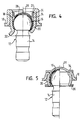
- FIG. 4 shows a second embodiment of a ball joint.
- the same reference numerals are used, and reference is made to the above explanations.
- the ball pin 12 is inserted in the second embodiment, that the connecting bolt 14 protrudes through the single-ended end of the wall 20. This end is suitably bent inwardly, so that the ball head 16 is securely held in the receiving space 18.
- the free end of the wall 20 is provided with a skirt 32, which is bent radially outward. On the skirt 32, a sealing bellows can be attached.
- an internal shoulder 34 is provided in the second embodiment, on which the collar 26 of the lid 28 abuts (see the illustration to the right of the center line).
- FIG. 5 shows an embodiment of a ball joint according to the invention.
- the wall 20 is designed only as a comparatively narrow ring, which does not protrude beyond the ball head 16 in the axial direction.
- a lid 28 is welded on the side of the wall, which is designed in two layers.
- a reinforcing ring 36 is welded on the other side of the wall 20, that is, at the end, which is made in one layer. This prevents even at low wall thickness of the wall 20, that it can not be bent at high loads on the axial ends of the receiving space 18 and the ball pin 12 securely in the receiving space 18 is held.
- the reinforcing ring 36 can be used for secure fixing of a sealing bellows on the ball joint.
Landscapes
- Engineering & Computer Science (AREA)
- General Engineering & Computer Science (AREA)
- Mechanical Engineering (AREA)
- Pivots And Pivotal Connections (AREA)
Applications Claiming Priority (2)
| Application Number | Priority Date | Filing Date | Title |
|---|---|---|---|
| DE20120251U DE20120251U1 (de) | 2001-12-12 | 2001-12-12 | Kugelgelenk |
| EP02795145A EP1454073B1 (fr) | 2001-12-12 | 2002-12-10 | Joint a rotule |
Related Parent Applications (1)
| Application Number | Title | Priority Date | Filing Date |
|---|---|---|---|
| EP02795145A Division EP1454073B1 (fr) | 2001-12-12 | 2002-12-10 | Joint a rotule |
Publications (2)
| Publication Number | Publication Date |
|---|---|
| EP1760337A2 true EP1760337A2 (fr) | 2007-03-07 |
| EP1760337A3 EP1760337A3 (fr) | 2007-05-09 |
Family
ID=7965162
Family Applications (3)
| Application Number | Title | Priority Date | Filing Date |
|---|---|---|---|
| EP02795145A Expired - Fee Related EP1454073B1 (fr) | 2001-12-12 | 2002-12-10 | Joint a rotule |
| EP06008875A Expired - Fee Related EP1681478B1 (fr) | 2001-12-12 | 2002-12-10 | Articulation à rotule |
| EP06023453A Withdrawn EP1760337A3 (fr) | 2001-12-12 | 2002-12-10 | Joint sphérique |
Family Applications Before (2)
| Application Number | Title | Priority Date | Filing Date |
|---|---|---|---|
| EP02795145A Expired - Fee Related EP1454073B1 (fr) | 2001-12-12 | 2002-12-10 | Joint a rotule |
| EP06008875A Expired - Fee Related EP1681478B1 (fr) | 2001-12-12 | 2002-12-10 | Articulation à rotule |
Country Status (6)
| Country | Link |
|---|---|
| EP (3) | EP1454073B1 (fr) |
| JP (1) | JP2005515366A (fr) |
| AU (1) | AU2002361043A1 (fr) |
| DE (3) | DE20120251U1 (fr) |
| PL (1) | PL362769A1 (fr) |
| WO (1) | WO2003054400A1 (fr) |
Cited By (2)
| Publication number | Priority date | Publication date | Assignee | Title |
|---|---|---|---|---|
| WO2013013779A1 (fr) * | 2011-07-28 | 2013-01-31 | Trw Automotive Gmbh | Carter de joint d'un joint à rotule et procédé de montage du carter de joint sur un élément de support |
| US11608854B2 (en) | 2017-08-16 | 2023-03-21 | Multimatic Inc. | Ball joint with injection molded bearing |
Families Citing this family (3)
| Publication number | Priority date | Publication date | Assignee | Title |
|---|---|---|---|---|
| DE10325280A1 (de) * | 2003-06-03 | 2005-01-05 | ZF Lemförder Metallwaren AG | Kugelgelenk und Verfahren zu dessen Herstellung |
| DE102013106707B4 (de) | 2013-06-26 | 2015-03-05 | Benteler Automobiltechnik Gmbh | Verfahren zur Herstellung eines Kraftfahrzeuglenkers mit Kugelgelenk |
| DE102015224616A1 (de) * | 2015-12-08 | 2017-06-08 | Robert Bosch Gmbh | Verfahren zum Befestigen einer Kugelschale in einer Gelenkstange und Gelenkstange mit Kugelschale |
Citations (7)
| Publication number | Priority date | Publication date | Assignee | Title |
|---|---|---|---|---|
| US2910316A (en) * | 1955-07-21 | 1959-10-27 | Thompson Ramo Wooldridge Inc | Stamped socket assembly |
| NL6715396A (fr) * | 1967-11-14 | 1969-05-19 | ||
| GB1363661A (en) * | 1972-08-11 | 1974-08-14 | Ada Halifax Ltd | Bearings for motors |
| DE2420241A1 (de) * | 1974-04-26 | 1975-11-06 | Bosch Gmbh Robert | Antriebsgestaengeteil |
| GB1547052A (en) * | 1976-05-29 | 1979-06-06 | Ehrenreich Gmbh & Co Kg A | Method of producing a ball-and-socked joint |
| US5061110A (en) * | 1991-02-08 | 1991-10-29 | Trw Inc. | Ball joint and method of assembly |
| JPH1037944A (ja) * | 1996-07-24 | 1998-02-13 | Otix:Kk | ボールジョイント構造体 |
Family Cites Families (7)
| Publication number | Priority date | Publication date | Assignee | Title |
|---|---|---|---|---|
| GB558161A (en) * | 1941-08-21 | 1943-12-23 | Leon Thiry | Improvements in or relating to ball and socket type joints |
| FR1153763A (fr) * | 1955-07-21 | 1958-03-21 | Thompson Prod Inc | Joint à rotule en tôle estampée |
| DE1266060B (de) * | 1962-09-27 | 1968-04-11 | Ehrenreich & Cie A | Verfahren zum Herstellen einer Ringwulst fuer das Befestigen eines Dichtungsbalges an einem Kugelgelenkgehaeuse |
| US3613201A (en) * | 1970-01-20 | 1971-10-19 | Trw Inc | Stamped ball joint assembly and method of making same |
| JPS5382957A (en) * | 1976-12-29 | 1978-07-21 | Tokai Trw & Co | Method of fastening ball joint |
| DE3018187A1 (de) * | 1980-05-13 | 1981-11-19 | Daimler-Benz Ag, 7000 Stuttgart | Kugelgelenk und verfahren zu dessen herstellung |
| DE4301303C1 (de) * | 1993-01-20 | 1994-08-18 | Lemfoerder Metallwaren Ag | Kugelgelenk |
-
2001
- 2001-12-12 DE DE20120251U patent/DE20120251U1/de not_active Expired - Lifetime
-
2002
- 2002-12-10 JP JP2003555084A patent/JP2005515366A/ja active Pending
- 2002-12-10 WO PCT/EP2002/014016 patent/WO2003054400A1/fr active IP Right Grant
- 2002-12-10 DE DE50209386T patent/DE50209386D1/de not_active Expired - Fee Related
- 2002-12-10 PL PL02362769A patent/PL362769A1/xx unknown
- 2002-12-10 AU AU2002361043A patent/AU2002361043A1/en not_active Abandoned
- 2002-12-10 DE DE50213250T patent/DE50213250D1/de not_active Expired - Lifetime
- 2002-12-10 EP EP02795145A patent/EP1454073B1/fr not_active Expired - Fee Related
- 2002-12-10 EP EP06008875A patent/EP1681478B1/fr not_active Expired - Fee Related
- 2002-12-10 EP EP06023453A patent/EP1760337A3/fr not_active Withdrawn
Patent Citations (7)
| Publication number | Priority date | Publication date | Assignee | Title |
|---|---|---|---|---|
| US2910316A (en) * | 1955-07-21 | 1959-10-27 | Thompson Ramo Wooldridge Inc | Stamped socket assembly |
| NL6715396A (fr) * | 1967-11-14 | 1969-05-19 | ||
| GB1363661A (en) * | 1972-08-11 | 1974-08-14 | Ada Halifax Ltd | Bearings for motors |
| DE2420241A1 (de) * | 1974-04-26 | 1975-11-06 | Bosch Gmbh Robert | Antriebsgestaengeteil |
| GB1547052A (en) * | 1976-05-29 | 1979-06-06 | Ehrenreich Gmbh & Co Kg A | Method of producing a ball-and-socked joint |
| US5061110A (en) * | 1991-02-08 | 1991-10-29 | Trw Inc. | Ball joint and method of assembly |
| JPH1037944A (ja) * | 1996-07-24 | 1998-02-13 | Otix:Kk | ボールジョイント構造体 |
Non-Patent Citations (1)
| Title |
|---|
| PATENT ABSTRACTS OF JAPAN Bd. 1998, Nr. 06, 30. April 1998 (1998-04-30) -& JP 10 037944 A (OTIX:KK), 13. Februar 1998 (1998-02-13) * |
Cited By (7)
| Publication number | Priority date | Publication date | Assignee | Title |
|---|---|---|---|---|
| WO2013013779A1 (fr) * | 2011-07-28 | 2013-01-31 | Trw Automotive Gmbh | Carter de joint d'un joint à rotule et procédé de montage du carter de joint sur un élément de support |
| CN103782046A (zh) * | 2011-07-28 | 2014-05-07 | Trw汽车股份有限公司 | 球窝关节的关节壳体以及用于将关节壳体装配在支架元件上的方法 |
| CN103782046B (zh) * | 2011-07-28 | 2016-08-17 | Trw汽车股份有限公司 | 球窝关节的关节壳体以及用于将关节壳体装配在支架元件上的方法 |
| US9429186B2 (en) | 2011-07-28 | 2016-08-30 | THK RHYTHM AUTOMOTIVE GmbH | Joint housing of a ball joint as well as method for mounting the joint housing on a carrier element |
| US10087983B2 (en) | 2011-07-28 | 2018-10-02 | THK RHYTIIM AUTOMOTIVE GmbH | Joint housing of a ball joint as well as method for mounting the joint housing on a carrier element |
| US11608854B2 (en) | 2017-08-16 | 2023-03-21 | Multimatic Inc. | Ball joint with injection molded bearing |
| US11649852B2 (en) | 2017-08-16 | 2023-05-16 | Multimatic Inc. | Ball joint with injection molded bearing |
Also Published As
| Publication number | Publication date |
|---|---|
| EP1454073A1 (fr) | 2004-09-08 |
| JP2005515366A (ja) | 2005-05-26 |
| EP1681478A3 (fr) | 2006-08-16 |
| EP1681478B1 (fr) | 2009-01-21 |
| PL362769A1 (en) | 2004-11-02 |
| AU2002361043A1 (en) | 2003-07-09 |
| DE50209386D1 (de) | 2007-03-15 |
| EP1454073B1 (fr) | 2007-01-24 |
| EP1760337A3 (fr) | 2007-05-09 |
| DE50213250D1 (de) | 2009-03-12 |
| EP1681478A2 (fr) | 2006-07-19 |
| WO2003054400A1 (fr) | 2003-07-03 |
| DE20120251U1 (de) | 2002-04-18 |
Similar Documents
| Publication | Publication Date | Title |
|---|---|---|
| DE19542071C2 (de) | Kugelgelenk | |
| DE102006016060B4 (de) | Radialgelenk und Verfahren zur Herstellung eines derartigen Radialgelenkes für ein Kraftfahrzeug | |
| WO2008055454A1 (fr) | Joint à rotule | |
| EP2737224B1 (fr) | Carter de joint d'un joint à rotule et procédé de montage du carter de joint sur un élément de support | |
| DE19630130C2 (de) | Endstück für den Einfüllstutzen eines Kraftfahrzeug-Kraftstofftankes | |
| DE19755020B4 (de) | Axialgelenk | |
| DE19622700A1 (de) | Zusammengesetztes und mit Gehäuse umgebenes Kugelgelenk | |
| EP1432920B1 (fr) | Joint a rotule | |
| DE112019003571T5 (de) | Kugelpfannenbaugruppe mit gepresster abdeckplatte und verfahren zu ihrer herstellung | |
| EP0155485B1 (fr) | Articulation à rotule axiale pour tige de guidage dans véhicules automobiles | |
| EP0924441A1 (fr) | Articulation à rotule et procédé pour la précontraindre | |
| WO2008074308A1 (fr) | Articulation sphérique avec anneau de fermeture | |
| EP1681478B1 (fr) | Articulation à rotule | |
| DE102018215172A1 (de) | Kugelgelenk für ein Fahrzeug sowie Verschlusselement für ein solches Kugelgelenk | |
| EP3054182B1 (fr) | Procédé de fabrication d'une liaison bout à bout entre un boîtier articulé et un composant de liaison et élément de construction fabriqué selon ledit procédé | |
| DE102011000934B4 (de) | Kugelgelenk, insbesondere für ein Fahrwerk eines Kraftfahrzeuges | |
| DE102004061057B4 (de) | Kugelgelenkverbindung zwischen einem Zapfen und einem Befestigungsteil | |
| EP0751310B1 (fr) | Articulation à rotule | |
| DE102016206864A1 (de) | Kugelgelenk, insbesondere für ein Fahrwerk eines Kraftfahrzeugs, sowie Verfahren zur Montage eines solchen Kugelgelenks | |
| EP1446587B1 (fr) | Articulation | |
| DE4412597C2 (de) | Kugelgelenk für Fahrwerksteile in einem Kraftfahrzeug | |
| EP0311811B1 (fr) | Articulation centrale à rotule avec soufflet d'étanchéité pour bras de suspension triangulaire de véhicule automobile | |
| EP0311810B1 (fr) | Joint à rotule démontable avec couvercle d'étanchéité pour véhicules automobiles | |
| EP3642060A1 (fr) | Procédé de fabrication d'un composant de véhicule et composant de véhicule fabriqué selon ce procédé | |
| DE102019209618B4 (de) | Kugelzapfen für ein Kugelgelenk, Kugelgelenk mit einem solchen Kugelzapfen und Verfahren zum Herstellen eines Kugelgelenks mit einem solchen Kugelzapfen |
Legal Events
| Date | Code | Title | Description |
|---|---|---|---|
| PUAI | Public reference made under article 153(3) epc to a published international application that has entered the european phase |
Free format text: ORIGINAL CODE: 0009012 |
|
| AC | Divisional application: reference to earlier application |
Ref document number: 1454073 Country of ref document: EP Kind code of ref document: P |
|
| AK | Designated contracting states |
Kind code of ref document: A2 Designated state(s): DE FR GB IT |
|
| PUAL | Search report despatched |
Free format text: ORIGINAL CODE: 0009013 |
|
| AK | Designated contracting states |
Kind code of ref document: A3 Designated state(s): DE FR GB IT |
|
| 17P | Request for examination filed |
Effective date: 20071011 |
|
| 17Q | First examination report despatched |
Effective date: 20071107 |
|
| AKX | Designation fees paid |
Designated state(s): DE FR GB IT |
|
| STAA | Information on the status of an ep patent application or granted ep patent |
Free format text: STATUS: THE APPLICATION IS DEEMED TO BE WITHDRAWN |
|
| 18D | Application deemed to be withdrawn |
Effective date: 20080518 |