EP1760218A2 - Stirrups for the construction of rebar reinforcements for reinforced concrete beams - Google Patents
Stirrups for the construction of rebar reinforcements for reinforced concrete beams Download PDFInfo
- Publication number
- EP1760218A2 EP1760218A2 EP06380232A EP06380232A EP1760218A2 EP 1760218 A2 EP1760218 A2 EP 1760218A2 EP 06380232 A EP06380232 A EP 06380232A EP 06380232 A EP06380232 A EP 06380232A EP 1760218 A2 EP1760218 A2 EP 1760218A2
- Authority
- EP
- European Patent Office
- Prior art keywords
- stirrups
- round bars
- reinforcements
- reinforced concrete
- construction
- Prior art date
- Legal status (The legal status is an assumption and is not a legal conclusion. Google has not performed a legal analysis and makes no representation as to the accuracy of the status listed.)
- Withdrawn
Links
Images

Classifications
-
- E—FIXED CONSTRUCTIONS
- E04—BUILDING
- E04C—STRUCTURAL ELEMENTS; BUILDING MATERIALS
- E04C5/00—Reinforcing elements, e.g. for concrete; Auxiliary elements therefor
- E04C5/01—Reinforcing elements of metal, e.g. with non-structural coatings
- E04C5/06—Reinforcing elements of metal, e.g. with non-structural coatings of high bending resistance, i.e. of essentially three-dimensional [3D] extent, e.g. lattice girders
- E04C5/0604—Prismatic or cylindrical reinforcement cages composed of longitudinal bars and open or closed stirrup rods
-
- E—FIXED CONSTRUCTIONS
- E04—BUILDING
- E04C—STRUCTURAL ELEMENTS; BUILDING MATERIALS
- E04C5/00—Reinforcing elements, e.g. for concrete; Auxiliary elements therefor
- E04C5/16—Auxiliary parts for reinforcements, e.g. connectors, spacers, stirrups
- E04C5/18—Spacers of metal or substantially of metal
Definitions
- This descriptive fact sheet refers to an application corresponding to stirrups for the construction of rebar reinforcements for reinforced concrete beams which enables the negative round bars to be placed on the top horizontal bar of the stirrup.
- This invention is to be applied in the construction industry, specifically in the manufacture of rebar reinforcements for reinforced concrete beams.
- the habitual elements that make up the reinforcement for reinforced concrete beams are: the top longitudinal round bars nos. 1 and 2; the bottom longitudinal round bars nos. 3 and 4, the stirrups no. 5; the bottom reinforcement round bars nos. 6 and 7 and the round bars for absorbing the negative moments nos. 8 and 9, as illustrated in figure 1.
- the drawing presented here is of a generic and non-exhaustive nature. When the reinforcements constructed according to this model are placed in situ, to position the negative round bars at the point determined by the calculation these must be shifted until placing them on the bottom part of the top horizontal transversal branch of the stirrups.
- This invention proposes constructing the stirrups in a way that the top horizontal bar is shaped with high and low sections so that the top longitudinal round bars are placed on the high sections and the top of the negative round bars are supported on the low sections.
- the vertical branches of the stirrups are anchored on the top longitudinal round bars above the round bars that cover the negative moments, meeting the conditions imposed by the shear and tangential stress calculation.
- the negative moments bars can be placed above the horizontal part of the transversal reinforcement as illustrated in figure 2. This system reduces the cost of manufacturing the reinforcements.
- This fact sheet refers to an invention patent application for the construction of rebar reinforcements for reinforced concrete beams using a type of stirrup that enables the negative round bars to be placed supported on the top part of the horizontal bar of the transversal reinforcement, whilst complying with the rules of the calculation for reinforced concrete as regards shear and tangential stress, thereby facilitating the placement in situ of the round bars for absorbing the negative moments as well as the construction in factory of the corresponding reinforcements.
- the formwork of the beams is put in place and the reinforcements of the beams are supported on it. Subsequently, the round bars of the negative moments are supported on the top part of the reinforcements instead of initially having to introduce them into a reinforcement, run them inside the reinforcement until the end of the negative round bars and then shift them through the inside of the other reinforcement as far as the position determined by the calculation, finishing off with the task of tying or welding them one by one under the top horizontal bar of the stirrups.
Landscapes
- Engineering & Computer Science (AREA)
- Architecture (AREA)
- Civil Engineering (AREA)
- Structural Engineering (AREA)
- Reinforcement Elements For Buildings (AREA)
Abstract
Description
- This descriptive fact sheet refers to an application corresponding to stirrups for the construction of rebar reinforcements for reinforced concrete beams which enables the negative round bars to be placed on the top horizontal bar of the stirrup.
- This invention is to be applied in the construction industry, specifically in the manufacture of rebar reinforcements for reinforced concrete beams.
- We are not aware of any precedents to this invention given that the calculation and construction manuals for reinforcements of reinforced concrete beams have always specified that the round bars for absorbing negative moments should be inside the stirrups
- The habitual elements that make up the reinforcement for reinforced concrete beams are: the top longitudinal round bars nos. 1 and 2; the bottom longitudinal round bars nos. 3 and 4, the stirrups no. 5; the bottom reinforcement round bars nos. 6 and 7 and the round bars for absorbing the negative moments nos. 8 and 9, as illustrated in figure 1. The drawing presented here is of a generic and non-exhaustive nature. When the reinforcements constructed according to this model are placed in situ, to position the negative round bars at the point determined by the calculation these must be shifted until placing them on the bottom part of the top horizontal transversal branch of the stirrups.
- This procedural method is very laborious due to the difficulty involved in shifting the negative moments reinforcements between the reinforcements of the pillars and placing them inside the reinforcements of generally two beams. We must bear in mind that this involves various rigid steel bars of considerable length.
- This invention proposes constructing the stirrups in a way that the top horizontal bar is shaped with high and low sections so that the top longitudinal round bars are placed on the high sections and the top of the negative round bars are supported on the low sections. In this manner, the vertical branches of the stirrups are anchored on the top longitudinal round bars above the round bars that cover the negative moments, meeting the conditions imposed by the shear and tangential stress calculation. The negative moments bars can be placed above the horizontal part of the transversal reinforcement as illustrated in figure 2. This system reduces the cost of manufacturing the reinforcements.
- This fact sheet refers to an invention patent application for the construction of rebar reinforcements for reinforced concrete beams using a type of stirrup that enables the negative round bars to be placed supported on the top part of the horizontal bar of the transversal reinforcement, whilst complying with the rules of the calculation for reinforced concrete as regards shear and tangential stress, thereby facilitating the placement in situ of the round bars for absorbing the negative moments as well as the construction in factory of the corresponding reinforcements.
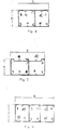
- To complete the description provided here and for the purpose of a better comprehension of the characteristics of the invention, attached to this descriptive fact sheet, as an inseparable part of it, is a set of illustrative and non-exhaustive plans representing the following:
- Figure 1 - Illustrates a section of the reinforcement with the conventional two-branch stirrup.
- Figure 2 - Illustrates a section of the reinforcement with the proposed stirrup.
- Figure 3 - Illustrates a section of the reinforcement with another variation of the proposed stirrup.
- Figure 4 - Illustrates a section of a reinforcement with a conventional stirrup of three vertical branches, and in this figure the round bars for absorbing the negative moments are nos. 9 and 10.
- Figure 5 - Illustrates a section of the reinforcement with the proposed stirrup, to substitute that of figure 4.
- Figure 6 - Illustrates a section of a reinforcement with the conventional four-branch stirrup. In this figure the round bars for absorbing the negative moments are nos. 11 and 12.
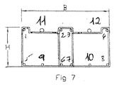
- Figure 7 - Illustrates a section of the reinforcement with the proposed stirrup to substitute that of figure 6.
- Given that the variety in shape and dimensions of the stirrups is unlimited, the above-mentioned drawings and the preferred embodiment of the invention refer to the most widely employed stirrups in construction. We must bear in mind that the novelty resides in that the top bar of the stirrups has high and low sections, i.e., a broken line.
- As we can see from these figures, this invention can be applied to all reinforced concrete structures as per the following instructions:
- The formwork of the beams is put in place and the reinforcements of the beams are supported on it. Subsequently, the round bars of the negative moments are supported on the top part of the reinforcements instead of initially having to introduce them into a reinforcement, run them inside the reinforcement until the end of the negative round bars and then shift them through the inside of the other reinforcement as far as the position determined by the calculation, finishing off with the task of tying or welding them one by one under the top horizontal bar of the stirrups.
- We consider it unnecessary to make this description more extensive as any expert in the field will understand the scope of the invention and the advantages that it entails
- The materials, shape, size and positioning of the elements will be subject to variation, provided that this does not alter the essence of the invention.
- The terms employed in this descriptive fact sheet should be interpreted in a broad and non-restrictive manner.
Claims (3)
- st - Stirrups for the construction of rebar reinforcements for reinforced concrete, characterised by their top horizontal bar being in the shape of a broken line, enabling the longitudinal round bars to be positioned on its higher sections and fastened by welding or any other joining method, with the round bars of the negative reinforcements supported on its lower sections.
- nd - Stirrups for the construction of rebar reinforcements for reinforced concrete, characterised by the method of placing the negative round bars as per claim no. 1, consisting of supporting these round bars over the lower section of the top bar of the stirrups of the beam's reinforcement.
- rd - Stirrups for the construction of rebar reinforcements for reinforced concrete, characterised because in their manufacture, the negative round bars can be joined as per claims nos. 1 and 2, enabling these to be placed on the top section of the stirrups of the beam's reinforcement at a single time without laborious operations
Applications Claiming Priority (1)
| Application Number | Priority Date | Filing Date | Title |
|---|---|---|---|
| ES200502118A ES2307357B1 (en) | 2005-08-29 | 2005-08-29 | ESTRIBOS FOR THE CONSTRUCTION OF FERRALLA ARMORS FOR BEAMS OF ARMED CONCRETE. |
Publications (2)
| Publication Number | Publication Date |
|---|---|
| EP1760218A2 true EP1760218A2 (en) | 2007-03-07 |
| EP1760218A3 EP1760218A3 (en) | 2009-01-07 |
Family
ID=37420915
Family Applications (1)
| Application Number | Title | Priority Date | Filing Date |
|---|---|---|---|
| EP06380232A Withdrawn EP1760218A3 (en) | 2005-08-29 | 2006-08-23 | Stirrups for the construction of rebar reinforcements for reinforced concrete beams |
Country Status (2)
| Country | Link |
|---|---|
| EP (1) | EP1760218A3 (en) |
| ES (1) | ES2307357B1 (en) |
Cited By (4)
| Publication number | Priority date | Publication date | Assignee | Title |
|---|---|---|---|---|
| CN101839042A (en) * | 2010-05-27 | 2010-09-22 | 大连阿尔滨集团有限公司 | Novel barricade rib used for negative bending moment rib |
| CN101956461A (en) * | 2010-10-15 | 2011-01-26 | 河海大学 | Steel bar arrangement method and steel bar arrangement device for reinforced concrete deep beam |
| CN117365014A (en) * | 2023-09-11 | 2024-01-09 | 上海宝冶集团有限公司 | Connecting method of upper longitudinal bars and closed stirrups of prefabricated superposed beam |
| CN117365015A (en) * | 2023-09-11 | 2024-01-09 | 上海宝冶集团有限公司 | Connecting structure of rear longitudinal ribs and downwarping stirrups on upper part of prefabricated superposed beam |
Family Cites Families (5)
| Publication number | Priority date | Publication date | Assignee | Title |
|---|---|---|---|---|
| GB595378A (en) * | 1945-05-07 | 1947-12-03 | Donovan Henry Lee | Improvements in reinforced concrete beams and columns |
| US1499984A (en) * | 1923-01-29 | 1924-07-01 | Stephen L Heidrich | Support |
| GB445937A (en) * | 1934-10-18 | 1936-04-20 | Joseph Leslie Musgrave | Improvements relating to reinforced concrete floors, roofs and like structures |
| GB1344294A (en) * | 1970-05-12 | 1974-01-16 | Oroschakoff G | Reinforcement for reinforced concrete structures |
| BE766864R (en) * | 1970-05-12 | 1971-10-01 | Oroschakoff Georgi | REINFORCEMENTS FOR CONSTRUCTIONS AND CONCRETE |
-
2005
- 2005-08-29 ES ES200502118A patent/ES2307357B1/en not_active Expired - Lifetime
-
2006
- 2006-08-23 EP EP06380232A patent/EP1760218A3/en not_active Withdrawn
Cited By (6)
| Publication number | Priority date | Publication date | Assignee | Title |
|---|---|---|---|---|
| CN101839042A (en) * | 2010-05-27 | 2010-09-22 | 大连阿尔滨集团有限公司 | Novel barricade rib used for negative bending moment rib |
| CN101839042B (en) * | 2010-05-27 | 2012-07-25 | 大连阿尔滨集团有限公司 | Novel barricade rib used for negative bending moment rib |
| CN101956461A (en) * | 2010-10-15 | 2011-01-26 | 河海大学 | Steel bar arrangement method and steel bar arrangement device for reinforced concrete deep beam |
| CN101956461B (en) * | 2010-10-15 | 2011-10-05 | 河海大学 | Reinforcement method and reinforcement device for reinforced concrete deep beams |
| CN117365014A (en) * | 2023-09-11 | 2024-01-09 | 上海宝冶集团有限公司 | Connecting method of upper longitudinal bars and closed stirrups of prefabricated superposed beam |
| CN117365015A (en) * | 2023-09-11 | 2024-01-09 | 上海宝冶集团有限公司 | Connecting structure of rear longitudinal ribs and downwarping stirrups on upper part of prefabricated superposed beam |
Also Published As
| Publication number | Publication date |
|---|---|
| ES2307357A1 (en) | 2008-11-16 |
| ES2307357B1 (en) | 2009-10-08 |
| EP1760218A3 (en) | 2009-01-07 |
Similar Documents
| Publication | Publication Date | Title |
|---|---|---|
| CN103088920B (en) | Pre-tensioning prestressed composite beam structural system and construction method thereof | |
| CN103711201B (en) | A long-span prestressed concrete beam-slab frame structure system | |
| CN102812190A (en) | Reinforced structure of spiral shear reinforcement and plate reinforcement using the shear reinforcement | |
| CN206815329U8 (en) | Pretensioned prestressed concrete corrosion-resistant hollow corner cut square pile | |
| CN201474095U (en) | Combined connection device of reverse construction concrete beam steel bar and positive construction type steel column | |
| EP1760218A2 (en) | Stirrups for the construction of rebar reinforcements for reinforced concrete beams | |
| JP2011043009A (en) | Reinforcing member around opening in reinforcing concrete beam with opening, and reinforcing structure and method using the same | |
| CN109853740A (en) | A composite column concrete beam joint structure and construction method | |
| KR101024991B1 (en) | Hollow slab deck plate structure and construction method of hollow slab deck plate | |
| CN108951418B (en) | Hinge joint structure of prefabricated hollow slab beam and construction method thereof | |
| GB1569816A (en) | Reinforced concrete construction | |
| KR20150004136A (en) | A web member for improving the connection structure of the node connecting of composite truss girder | |
| KR101389044B1 (en) | Steel girders for bridges and its production method | |
| JP3658337B2 (en) | Spot welding method for shear reinforcement | |
| JP5866038B1 (en) | Deck plate, floor slab, deck plate manufacturing method, and floor slab construction method | |
| KR101585896B1 (en) | PHC pile connecting structure comprising shortened PHC pile with reinforced head for footing foundation | |
| JP6310648B2 (en) | Joint structure of reinforced concrete member and steel member | |
| CN105888135A (en) | Novel steel-concrete combined open web girder and manufacturing method thereof | |
| CN211735742U (en) | Connecting joint of precast beam and cast-in-place structure | |
| EP1770228A2 (en) | Rebar reinforcement for reinforced concrete beams | |
| CN211228064U (en) | U-shaped thin-walled steel-prestressed concrete composite beam | |
| KR20100018170A (en) | Inverted triangle truss slab form | |
| CN102953375B (en) | Prestressed Foundation Pile and Its Pile Connection Method and Pile Head Treatment Method | |
| JP3939686B2 (en) | Formwork panel and building formwork using the same and concrete foundation | |
| KR20090017083A (en) | Reinforcement structure for load transfer to the joint and its construction method |
Legal Events
| Date | Code | Title | Description |
|---|---|---|---|
| PUAI | Public reference made under article 153(3) epc to a published international application that has entered the european phase |
Free format text: ORIGINAL CODE: 0009012 |
|
| 17P | Request for examination filed |
Effective date: 20060824 |
|
| AK | Designated contracting states |
Kind code of ref document: A2 Designated state(s): AT BE BG CH CY CZ DE DK EE ES FI FR GB GR HU IE IS IT LI LT LU LV MC NL PL PT RO SE SI SK TR |
|
| AX | Request for extension of the european patent |
Extension state: AL BA HR MK YU |
|
| PUAL | Search report despatched |
Free format text: ORIGINAL CODE: 0009013 |
|
| AK | Designated contracting states |
Kind code of ref document: A3 Designated state(s): AT BE BG CH CY CZ DE DK EE ES FI FR GB GR HU IE IS IT LI LT LU LV MC NL PL PT RO SE SI SK TR |
|
| AX | Request for extension of the european patent |
Extension state: AL BA HR MK RS |
|
| AKX | Designation fees paid |
Designated state(s): AT BE BG CH CY CZ DE DK EE ES FI FR GB GR HU IE IS IT LI LT LU LV MC NL PL PT RO SE SI SK TR |
|
| STAA | Information on the status of an ep patent application or granted ep patent |
Free format text: STATUS: THE APPLICATION IS DEEMED TO BE WITHDRAWN |
|
| 18D | Application deemed to be withdrawn |
Effective date: 20090708 |