EP1760167B1 - Vorrichtung zum Herstellen eines Stahlrohres und Verfahren zur ihrer Herstellung - Google Patents
Vorrichtung zum Herstellen eines Stahlrohres und Verfahren zur ihrer Herstellung Download PDFInfo
- Publication number
- EP1760167B1 EP1760167B1 EP06119227.4A EP06119227A EP1760167B1 EP 1760167 B1 EP1760167 B1 EP 1760167B1 EP 06119227 A EP06119227 A EP 06119227A EP 1760167 B1 EP1760167 B1 EP 1760167B1
- Authority
- EP
- European Patent Office
- Prior art keywords
- steel tube
- tube
- alloy
- molten alloy
- plating part
- Prior art date
- Legal status (The legal status is an assumption and is not a legal conclusion. Google has not performed a legal analysis and makes no representation as to the accuracy of the status listed.)
- Ceased
Links
- 229910000831 Steel Inorganic materials 0.000 title claims description 132
- 239000010959 steel Substances 0.000 title claims description 132
- 238000000034 method Methods 0.000 title claims description 35
- 238000004519 manufacturing process Methods 0.000 title claims description 22
- 239000000956 alloy Substances 0.000 claims description 54
- 229910045601 alloy Inorganic materials 0.000 claims description 54
- 238000007747 plating Methods 0.000 claims description 40
- 239000007789 gas Substances 0.000 claims description 15
- IJGRMHOSHXDMSA-UHFFFAOYSA-N Atomic nitrogen Chemical compound N#N IJGRMHOSHXDMSA-UHFFFAOYSA-N 0.000 claims description 14
- 238000001816 cooling Methods 0.000 claims description 12
- 239000000498 cooling water Substances 0.000 claims description 8
- 238000010438 heat treatment Methods 0.000 claims description 8
- 229910052757 nitrogen Inorganic materials 0.000 claims description 7
- UFHFLCQGNIYNRP-UHFFFAOYSA-N Hydrogen Chemical compound [H][H] UFHFLCQGNIYNRP-UHFFFAOYSA-N 0.000 claims description 5
- HCHKCACWOHOZIP-UHFFFAOYSA-N Zinc Chemical compound [Zn] HCHKCACWOHOZIP-UHFFFAOYSA-N 0.000 claims description 5
- 229910052782 aluminium Inorganic materials 0.000 claims description 5
- XAGFODPZIPBFFR-UHFFFAOYSA-N aluminium Chemical compound [Al] XAGFODPZIPBFFR-UHFFFAOYSA-N 0.000 claims description 5
- 239000001257 hydrogen Substances 0.000 claims description 5
- 229910052739 hydrogen Inorganic materials 0.000 claims description 5
- 238000002347 injection Methods 0.000 claims description 5
- 239000007924 injection Substances 0.000 claims description 5
- 238000005192 partition Methods 0.000 claims description 5
- 238000002203 pretreatment Methods 0.000 claims description 5
- 239000011701 zinc Substances 0.000 claims description 5
- 229910052725 zinc Inorganic materials 0.000 claims description 5
- 230000007797 corrosion Effects 0.000 claims description 4
- 238000005260 corrosion Methods 0.000 claims description 4
- 230000009977 dual effect Effects 0.000 claims description 4
- 238000010791 quenching Methods 0.000 claims description 3
- 238000007664 blowing Methods 0.000 claims description 2
- 238000002844 melting Methods 0.000 claims description 2
- 230000008018 melting Effects 0.000 claims description 2
- 230000000171 quenching effect Effects 0.000 claims description 2
- 238000005507 spraying Methods 0.000 claims description 2
- 238000000137 annealing Methods 0.000 claims 2
- 238000003780 insertion Methods 0.000 claims 1
- 230000037431 insertion Effects 0.000 claims 1
- 238000009740 moulding (composite fabrication) Methods 0.000 description 6
- 238000003466 welding Methods 0.000 description 5
- 239000011261 inert gas Substances 0.000 description 4
- 230000033228 biological regulation Effects 0.000 description 3
- 238000004532 chromating Methods 0.000 description 3
- 238000002845 discoloration Methods 0.000 description 3
- 230000005484 gravity Effects 0.000 description 3
- 230000006698 induction Effects 0.000 description 3
- 230000003647 oxidation Effects 0.000 description 3
- 238000007254 oxidation reaction Methods 0.000 description 3
- 229910052710 silicon Inorganic materials 0.000 description 3
- 239000010703 silicon Substances 0.000 description 3
- 229910018137 Al-Zn Inorganic materials 0.000 description 2
- 229910018573 Al—Zn Inorganic materials 0.000 description 2
- 238000005520 cutting process Methods 0.000 description 2
- 238000003618 dip coating Methods 0.000 description 2
- 229910052751 metal Inorganic materials 0.000 description 2
- 239000002184 metal Substances 0.000 description 2
- 238000004381 surface treatment Methods 0.000 description 2
- XLYOFNOQVPJJNP-UHFFFAOYSA-N water Substances O XLYOFNOQVPJJNP-UHFFFAOYSA-N 0.000 description 2
- 241001163841 Albugo ipomoeae-panduratae Species 0.000 description 1
- 230000001154 acute effect Effects 0.000 description 1
- 239000011324 bead Substances 0.000 description 1
- 239000011248 coating agent Substances 0.000 description 1
- 238000000576 coating method Methods 0.000 description 1
- 238000009500 colour coating Methods 0.000 description 1
- 238000004891 communication Methods 0.000 description 1
- 230000001276 controlling effect Effects 0.000 description 1
- 230000007547 defect Effects 0.000 description 1
- 238000007599 discharging Methods 0.000 description 1
- 238000005516 engineering process Methods 0.000 description 1
- 238000005246 galvanizing Methods 0.000 description 1
- 150000002431 hydrogen Chemical class 0.000 description 1
- 230000001105 regulatory effect Effects 0.000 description 1
- 239000000126 substance Substances 0.000 description 1
- 239000004094 surface-active agent Substances 0.000 description 1
Images


Classifications
-
- B—PERFORMING OPERATIONS; TRANSPORTING
- B21—MECHANICAL METAL-WORKING WITHOUT ESSENTIALLY REMOVING MATERIAL; PUNCHING METAL
- B21D—WORKING OR PROCESSING OF SHEET METAL OR METAL TUBES, RODS OR PROFILES WITHOUT ESSENTIALLY REMOVING MATERIAL; PUNCHING METAL
- B21D51/00—Making hollow objects
-
- C—CHEMISTRY; METALLURGY
- C21—METALLURGY OF IRON
- C21D—MODIFYING THE PHYSICAL STRUCTURE OF FERROUS METALS; GENERAL DEVICES FOR HEAT TREATMENT OF FERROUS OR NON-FERROUS METALS OR ALLOYS; MAKING METAL MALLEABLE, e.g. BY DECARBURISATION OR TEMPERING
- C21D1/00—General methods or devices for heat treatment, e.g. annealing, hardening, quenching or tempering
-
- C—CHEMISTRY; METALLURGY
- C23—COATING METALLIC MATERIAL; COATING MATERIAL WITH METALLIC MATERIAL; CHEMICAL SURFACE TREATMENT; DIFFUSION TREATMENT OF METALLIC MATERIAL; COATING BY VACUUM EVAPORATION, BY SPUTTERING, BY ION IMPLANTATION OR BY CHEMICAL VAPOUR DEPOSITION, IN GENERAL; INHIBITING CORROSION OF METALLIC MATERIAL OR INCRUSTATION IN GENERAL
- C23C—COATING METALLIC MATERIAL; COATING MATERIAL WITH METALLIC MATERIAL; SURFACE TREATMENT OF METALLIC MATERIAL BY DIFFUSION INTO THE SURFACE, BY CHEMICAL CONVERSION OR SUBSTITUTION; COATING BY VACUUM EVAPORATION, BY SPUTTERING, BY ION IMPLANTATION OR BY CHEMICAL VAPOUR DEPOSITION, IN GENERAL
- C23C2/00—Hot-dipping or immersion processes for applying the coating material in the molten state without affecting the shape; Apparatus therefor
-
- C—CHEMISTRY; METALLURGY
- C23—COATING METALLIC MATERIAL; COATING MATERIAL WITH METALLIC MATERIAL; CHEMICAL SURFACE TREATMENT; DIFFUSION TREATMENT OF METALLIC MATERIAL; COATING BY VACUUM EVAPORATION, BY SPUTTERING, BY ION IMPLANTATION OR BY CHEMICAL VAPOUR DEPOSITION, IN GENERAL; INHIBITING CORROSION OF METALLIC MATERIAL OR INCRUSTATION IN GENERAL
- C23C—COATING METALLIC MATERIAL; COATING MATERIAL WITH METALLIC MATERIAL; SURFACE TREATMENT OF METALLIC MATERIAL BY DIFFUSION INTO THE SURFACE, BY CHEMICAL CONVERSION OR SUBSTITUTION; COATING BY VACUUM EVAPORATION, BY SPUTTERING, BY ION IMPLANTATION OR BY CHEMICAL VAPOUR DEPOSITION, IN GENERAL
- C23C2/00—Hot-dipping or immersion processes for applying the coating material in the molten state without affecting the shape; Apparatus therefor
- C23C2/02—Pretreatment of the material to be coated, e.g. for coating on selected surface areas
-
- C—CHEMISTRY; METALLURGY
- C23—COATING METALLIC MATERIAL; COATING MATERIAL WITH METALLIC MATERIAL; CHEMICAL SURFACE TREATMENT; DIFFUSION TREATMENT OF METALLIC MATERIAL; COATING BY VACUUM EVAPORATION, BY SPUTTERING, BY ION IMPLANTATION OR BY CHEMICAL VAPOUR DEPOSITION, IN GENERAL; INHIBITING CORROSION OF METALLIC MATERIAL OR INCRUSTATION IN GENERAL
- C23C—COATING METALLIC MATERIAL; COATING MATERIAL WITH METALLIC MATERIAL; SURFACE TREATMENT OF METALLIC MATERIAL BY DIFFUSION INTO THE SURFACE, BY CHEMICAL CONVERSION OR SUBSTITUTION; COATING BY VACUUM EVAPORATION, BY SPUTTERING, BY ION IMPLANTATION OR BY CHEMICAL VAPOUR DEPOSITION, IN GENERAL
- C23C2/00—Hot-dipping or immersion processes for applying the coating material in the molten state without affecting the shape; Apparatus therefor
- C23C2/02—Pretreatment of the material to be coated, e.g. for coating on selected surface areas
- C23C2/022—Pretreatment of the material to be coated, e.g. for coating on selected surface areas by heating
- C23C2/0222—Pretreatment of the material to be coated, e.g. for coating on selected surface areas by heating in a reactive atmosphere, e.g. oxidising or reducing atmosphere
-
- C—CHEMISTRY; METALLURGY
- C23—COATING METALLIC MATERIAL; COATING MATERIAL WITH METALLIC MATERIAL; CHEMICAL SURFACE TREATMENT; DIFFUSION TREATMENT OF METALLIC MATERIAL; COATING BY VACUUM EVAPORATION, BY SPUTTERING, BY ION IMPLANTATION OR BY CHEMICAL VAPOUR DEPOSITION, IN GENERAL; INHIBITING CORROSION OF METALLIC MATERIAL OR INCRUSTATION IN GENERAL
- C23C—COATING METALLIC MATERIAL; COATING MATERIAL WITH METALLIC MATERIAL; SURFACE TREATMENT OF METALLIC MATERIAL BY DIFFUSION INTO THE SURFACE, BY CHEMICAL CONVERSION OR SUBSTITUTION; COATING BY VACUUM EVAPORATION, BY SPUTTERING, BY ION IMPLANTATION OR BY CHEMICAL VAPOUR DEPOSITION, IN GENERAL
- C23C2/00—Hot-dipping or immersion processes for applying the coating material in the molten state without affecting the shape; Apparatus therefor
- C23C2/02—Pretreatment of the material to be coated, e.g. for coating on selected surface areas
- C23C2/022—Pretreatment of the material to be coated, e.g. for coating on selected surface areas by heating
- C23C2/0224—Two or more thermal pretreatments
-
- C—CHEMISTRY; METALLURGY
- C23—COATING METALLIC MATERIAL; COATING MATERIAL WITH METALLIC MATERIAL; CHEMICAL SURFACE TREATMENT; DIFFUSION TREATMENT OF METALLIC MATERIAL; COATING BY VACUUM EVAPORATION, BY SPUTTERING, BY ION IMPLANTATION OR BY CHEMICAL VAPOUR DEPOSITION, IN GENERAL; INHIBITING CORROSION OF METALLIC MATERIAL OR INCRUSTATION IN GENERAL
- C23C—COATING METALLIC MATERIAL; COATING MATERIAL WITH METALLIC MATERIAL; SURFACE TREATMENT OF METALLIC MATERIAL BY DIFFUSION INTO THE SURFACE, BY CHEMICAL CONVERSION OR SUBSTITUTION; COATING BY VACUUM EVAPORATION, BY SPUTTERING, BY ION IMPLANTATION OR BY CHEMICAL VAPOUR DEPOSITION, IN GENERAL
- C23C2/00—Hot-dipping or immersion processes for applying the coating material in the molten state without affecting the shape; Apparatus therefor
- C23C2/02—Pretreatment of the material to be coated, e.g. for coating on selected surface areas
- C23C2/024—Pretreatment of the material to be coated, e.g. for coating on selected surface areas by cleaning or etching
-
- C—CHEMISTRY; METALLURGY
- C23—COATING METALLIC MATERIAL; COATING MATERIAL WITH METALLIC MATERIAL; CHEMICAL SURFACE TREATMENT; DIFFUSION TREATMENT OF METALLIC MATERIAL; COATING BY VACUUM EVAPORATION, BY SPUTTERING, BY ION IMPLANTATION OR BY CHEMICAL VAPOUR DEPOSITION, IN GENERAL; INHIBITING CORROSION OF METALLIC MATERIAL OR INCRUSTATION IN GENERAL
- C23C—COATING METALLIC MATERIAL; COATING MATERIAL WITH METALLIC MATERIAL; SURFACE TREATMENT OF METALLIC MATERIAL BY DIFFUSION INTO THE SURFACE, BY CHEMICAL CONVERSION OR SUBSTITUTION; COATING BY VACUUM EVAPORATION, BY SPUTTERING, BY ION IMPLANTATION OR BY CHEMICAL VAPOUR DEPOSITION, IN GENERAL
- C23C2/00—Hot-dipping or immersion processes for applying the coating material in the molten state without affecting the shape; Apparatus therefor
- C23C2/04—Hot-dipping or immersion processes for applying the coating material in the molten state without affecting the shape; Apparatus therefor characterised by the coating material
- C23C2/12—Aluminium or alloys based thereon
-
- C—CHEMISTRY; METALLURGY
- C23—COATING METALLIC MATERIAL; COATING MATERIAL WITH METALLIC MATERIAL; CHEMICAL SURFACE TREATMENT; DIFFUSION TREATMENT OF METALLIC MATERIAL; COATING BY VACUUM EVAPORATION, BY SPUTTERING, BY ION IMPLANTATION OR BY CHEMICAL VAPOUR DEPOSITION, IN GENERAL; INHIBITING CORROSION OF METALLIC MATERIAL OR INCRUSTATION IN GENERAL
- C23C—COATING METALLIC MATERIAL; COATING MATERIAL WITH METALLIC MATERIAL; SURFACE TREATMENT OF METALLIC MATERIAL BY DIFFUSION INTO THE SURFACE, BY CHEMICAL CONVERSION OR SUBSTITUTION; COATING BY VACUUM EVAPORATION, BY SPUTTERING, BY ION IMPLANTATION OR BY CHEMICAL VAPOUR DEPOSITION, IN GENERAL
- C23C2/00—Hot-dipping or immersion processes for applying the coating material in the molten state without affecting the shape; Apparatus therefor
- C23C2/50—Controlling or regulating the coating processes
-
- C—CHEMISTRY; METALLURGY
- C23—COATING METALLIC MATERIAL; COATING MATERIAL WITH METALLIC MATERIAL; CHEMICAL SURFACE TREATMENT; DIFFUSION TREATMENT OF METALLIC MATERIAL; COATING BY VACUUM EVAPORATION, BY SPUTTERING, BY ION IMPLANTATION OR BY CHEMICAL VAPOUR DEPOSITION, IN GENERAL; INHIBITING CORROSION OF METALLIC MATERIAL OR INCRUSTATION IN GENERAL
- C23C—COATING METALLIC MATERIAL; COATING MATERIAL WITH METALLIC MATERIAL; SURFACE TREATMENT OF METALLIC MATERIAL BY DIFFUSION INTO THE SURFACE, BY CHEMICAL CONVERSION OR SUBSTITUTION; COATING BY VACUUM EVAPORATION, BY SPUTTERING, BY ION IMPLANTATION OR BY CHEMICAL VAPOUR DEPOSITION, IN GENERAL
- C23C2/00—Hot-dipping or immersion processes for applying the coating material in the molten state without affecting the shape; Apparatus therefor
- C23C2/50—Controlling or regulating the coating processes
- C23C2/52—Controlling or regulating the coating processes with means for measuring or sensing
- C23C2/523—Bath level or amount
-
- Y—GENERAL TAGGING OF NEW TECHNOLOGICAL DEVELOPMENTS; GENERAL TAGGING OF CROSS-SECTIONAL TECHNOLOGIES SPANNING OVER SEVERAL SECTIONS OF THE IPC; TECHNICAL SUBJECTS COVERED BY FORMER USPC CROSS-REFERENCE ART COLLECTIONS [XRACs] AND DIGESTS
- Y10—TECHNICAL SUBJECTS COVERED BY FORMER USPC
- Y10T—TECHNICAL SUBJECTS COVERED BY FORMER US CLASSIFICATION
- Y10T29/00—Metal working
- Y10T29/49—Method of mechanical manufacture
- Y10T29/4998—Combined manufacture including applying or shaping of fluent material
-
- Y—GENERAL TAGGING OF NEW TECHNOLOGICAL DEVELOPMENTS; GENERAL TAGGING OF CROSS-SECTIONAL TECHNOLOGIES SPANNING OVER SEVERAL SECTIONS OF THE IPC; TECHNICAL SUBJECTS COVERED BY FORMER USPC CROSS-REFERENCE ART COLLECTIONS [XRACs] AND DIGESTS
- Y10—TECHNICAL SUBJECTS COVERED BY FORMER USPC
- Y10T—TECHNICAL SUBJECTS COVERED BY FORMER US CLASSIFICATION
- Y10T29/00—Metal working
- Y10T29/51—Plural diverse manufacturing apparatus including means for metal shaping or assembling
- Y10T29/5185—Tube making
Definitions
- the present invention relates to an apparatus and method for manufacturing a steel tube, and more particularly, an apparatus and method for manufacturing a steel tube having an improved surface treatment structure.
- methods for manufacturing a steel tube include an injection method and a method of forming a steel plate into a tube shape. Since the injection method is more costly, the method using a steel plate is widely used.
- a steel tube manufactured by the steel plate method is referred to as an electric-welded tube, since the steel plate is deformed into a tube shape and its ends are welded together using an electric-resistance welding method.
- the method for manufacturing an electric-welded tube is widely employed in most steel tube manufacturing methods, from small to large diameter tubes.
- a small diameter steel tube manufactured as described above is widely used in a condenser of a cooling apparatus such as a refrigerator, a hydraulic line of a brake system, and other such applications which require high durability and reliability. Therefore, such a small diameter steel tube should be manufactured carefully.
- US 3,559,280 discloses a method and apparatus for tube forming, galvanizing and colour coating of a metal strip in a continuous operation.
- GB 676 198 A discloses a method for continuous hot dip coating of metallic objects including heat treatment prior to coating.
- the present invention has been made in view of the above problems, and it is an object of the present invention to provide an apparatus and method for manufacturing a steel tube, a surface of which is plated to have improved corrosion resistance.
- FIG 1 is a schematic view of an apparatus for manufacturing a steel tube in accordance with an exemplary embodiment of the present invention.
- an apparatus for manufacturing a steel tube in accordance with an exemplary embodiment of the present invention includes a tube-forming device for forming a steel plate into a steel tube, and a device for plating a surface of the steel tube with an alloy, the two devices integrally formed in a single line.
- a tube-forming device for forming a steel plate into a steel tube and a device for plating a surface of the steel tube with an alloy, the two devices integrally formed in a single line.
- the tube-forming device may include an uncoiling device A for flattening a coiled steel plate, a butt welding device B for welding a plurality of steel plates together, a looping device C for discharging the welded steel plates while maintaining a looped state of the steel plates in order to uniformly supply the steel plates, an electric-resistance welding device D for forming the steel plate into a tube and welding its juncture, a cooling device E for cooling the formed steel tube to an appropriate temperature, and a reducing device F for reducing the diameter of the steel tube to a certain standard.
- an uncoiling device A for flattening a coiled steel plate
- a butt welding device B for welding a plurality of steel plates together
- a looping device C for discharging the welded steel plates while maintaining a looped state of the steel plates in order to uniformly supply the steel plates
- an electric-resistance welding device D for forming the steel plate into a tube and welding its juncture
- the cooling device E may further include a cutting device for smoothly cutting a bead part of the steel tube 1, i.e., a welded part, to prevent generation of defects in the steel tube during the following plating process.
- a surfactant is used to chemically treat a surface of the steel tube 1. Then, foreign substances such as oxide attached to the surface of the steel tube are physically removed by a rapidly rotating wire brush, etc., and the surface of the steel tube is cleaned using water and air.
- the steel tube 1 passes through a heat treatment device 7, a pre-treatment device 10, and a plating device 20, and a SeAHLume alloy is plated on the surface of the steel tube 1.
- the steel tube 1 is heated to a high temperature of 750 ⁇ 850°C using an induction coil of the heat treatment device 7, thereby being heat treated to improve mechanical properties of the steel tube 1.
- the steel tube 1 passes through the pre-treatment device 10, which includes a dual tube 9, a gas injection device 8a, and a cooling water supply device 8b.
- the dual tube 9 includes an inner tube 9b surrounding the steel tube 1, and an outer tube 9a disposed around the periphery of the inner tube 9b.
- the steel tube 1 moves through the center of the inner tube 9b.
- a mixed gas is supplied into the inner tube 9b by the gas injection device 8a to form a reduction atmosphere.
- the mixed gas is formed of 10 ⁇ 30% reduction gas such as hydrogen, and 70 ⁇ 90% inert gas such as nitrogen. Flow rates of the hydrogen and nitrogen may be adjusted by controlling flow meters after regulating the pressure in each tube. And, the gas whose flow rates are adjusted may be mixed and passed through a single mixed gas tube.
- the reduction atmosphere described above can prevent black oxidation of the surface of the heated steel tube, thereby enabling the following plating process to be performed more stably.
- cooling water is supplied between the inner tube 9b and the outer tube 9a to anneal the steel tube 1 to about 570 ⁇ 620°C.
- a space between the inner tube 9b and the outer tube 9a is connected to the cooling water supply device 8b for supplying cooling water which absorbs heat and discharges it to the exterior.
- the steel tube 1 may be pre-heated by an optional pre-heating device 11.
- the plating device 20 is a device for plating the surface of the steel tube 1 with a corrosion-resistant alloy, and may include a heater 22 and a pot 21 for storing molten alloy.
- the alloy (referred to as a SeAHLume alloy) includes 55wt% aluminum and 43.4 ⁇ 44.9wt% zinc, which has excellent corrosion-resistance.
- the alloy may further include 0.1 ⁇ 1.6wt% silicon.
- the heater 22 may be installed at a lower part of the pot 21 for melting the alloy using an induction heating method.
- the pot 21 is a vessel for storing the molten alloy and may include a plating part 21a projecting from its one side and disposed on a path through which the steel tube 1 passes. That is, a portion of the molten alloy is introduced into the plating part 21a, and the surface of the steel tube 1 moving through a hole formed at the plating part 21a is plated with the alloy.
- the path along which the steel tube 1 passes through the plating part 21 a may be vertical. That is, the steel tube 1 may be vertically moved between an upper guide roller 31 and a lower guide roller 30, thereby preventing the alloy from being unevenly plated due to gravity.
- the steel tube 1 After vertically raising the steel tube 1, the steel tube 1 is lowered by the upper guide roller 31 at a predetermined angle to be moved to the following process.
- the steel tube 1 arrives at a horizontal moving region, it is cooled by an air-cooling or water-cooling device 15.
- the cooling process may be performed by blowing air and/or spraying water onto the surface of the steel tube 1 (quenching).
- the steel tube 1 manufactured by the above devices is tested for leakage and then wound into a coil in order to be moved to following process. Then, in order to prevent discoloration such as blacking or white rust on the plated surface of the steel tube 1, a Cr 3+ chromating process may be performed on the surface of the steel tube 1 by a chromating device for 5 seconds or less, and preferably 1 second or less.
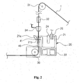
- FIG 2 is a cross-sectional view of a plating apparatus in accordance with an exemplary embodiment of the present invention.
- the constitution of the plating device will now be described in detail with reference to FIG 2 .
- the induction heater 22 is installed at a lower part of the pot 21, and the plating part 21 a projects from one side of the pot 21.
- the steel tube 1 vertically passes through the path of the plating part 21 a, which includes the upper and lower guide rollers 31 and 30 installed at upper and lower ends thereof to guide movement of the steel tube 1.
- the formed steel tube 1 should be connected at both sides to vertically pass through the plating part 21a.
- the steel tube 1 is introduced under the lower guide roller 30 horizontally, and bent upward to be moved substantially vertically.
- the lower guide roller 30 is surrounded by a case which may include an auxiliary tool for adjusting a gap due to a diameter difference of the steel tube 1.
- the steel tube 1 passes through the plating part 21a to be plated with a SeAHLume alloy composed of 55wt% aluminum and 43.4 ⁇ 44.9wt% zinc.
- the alloy may further include 0.1 ⁇ 1.6wt% silicon. Meanwhile, there is no need to always store the molten alloy in the plating part 21 a, and a level of the molten alloy introduced into the plating part 21 a can be adjusted by a level block 26, which may be selectively inserted into the pot 21.
- the pot 21 includes a partition 24 installed therein to divide an upper space, and the level block 26 is installed to be vertically movable at one side of the partition 24.
- the partition 24 prevents waves in the molten alloy around the plating part 21 a due to vertical movement of the level block 26.
- the level block 26 is moved downward to be dipped in the molten alloy, the level of the molten alloy is raised to introduce the molten alloy into the plating part 21 a.
- the level block 26 is moved upward, the level of the molten alloy is lowered to remove the molten alloy from the plating part 21 a.
- the plating part 21a has a hole 21b at its bottom surface for the steel tube 1 to pass through, and a pressure regulation device for preventing leakage of the molten alloy through the hole 21b.
- the pressure regulation device may include a lower nozzle device 41 and a guide pipe 40.
- the guide pipe 40 is connected to the case surrounding the lower guide roller 30, and an inert gas such as nitrogen is supplied into the guide pipe 40 at a pressure of 0.1 ⁇ 0.3 bar to maintain a pressure higher than atmospheric pressure.
- the guide pipe 40 is in communication with the lower nozzle device 41 at its upper end, and the lower nozzle device 41 is also maintained at a high pressure to prevent the molten alloy in the plating part 21 a from leaking downward.
- guide nozzles may be installed at upper and lower parts of the lower nozzle device 41 and replaced as necessary to fit the outer diameter of the steel tube 1.
- the steel tube 1 since the steel tube 1 is vertically moved in a direction opposite to gravity, the steel tube 1 can be uniformly plated with the molten alloy while passing through the plating part 21 a. That is, the molten alloy plated on the steel tube 1 can flow downward due to the gravity, thereby preventing the steel tube 1 from being plated with uneven thickness.
- an upper nozzle device 34 may be installed over the plating part 21a to inject air or other mixed gas.
- a small amount of hydrogen gas may be supplied to the steel tube 1 to generate a flame.
- an inert gas such as nitrogen may be blown onto the steel tube 1 through the upper nozzle device 34 to adjust the thickness of the alloy plated on the steel tube 1.
- the steel tube 1 passed through the plating part 21 a is continuously moved vertically upward a distance of about 20m.
- at least one tubular cooling device 32 is installed along the moving path to surround the steel tube 1. Therefore, the surface of the steel tube 1 can be cooled to a predetermined temperature or lower by the air blown from the tubular cooling device 32.
- the upper guide roller 31 is installed at an upper end of the moving path of the steel tube 1, and the steel tube 1 is bent by the upper guide roller 31 to form an acute angle of less than about 30° and then moved to the following cooling device.
- the following processes are the same as described with reference to FIG. 1 .
- FIG. 3 is a flowchart showing a method for manufacturing a steel tube in accordance with an exemplary embodiment of the present invention.
- a steel plate is formed into a steel tube (S10).
- the formed steel tube is heated to a high temperature of 750 ⁇ 850°C to be heat-treated (S20).
- the steel tube is annealed to a temperature of 570 ⁇ 620°C and a reduction atmosphere is provided to perform pre-treatment (S30).
- the reduction atmosphere is provided by introducing a mixed gas of hydrogen and nitrogen around the steel tube.
- a SeAHLume alloy composed of 55wt% aluminum, 43.4 ⁇ 44.9wt% zinc, and 0.1 ⁇ 1.6wt% silicon is molten, and a surface of the steel tube is plated with the molten alloy (S40).
- the SeAHLume alloy has strong corrosion-resistance.
- the steel tube vertically passes through a pot with the molten alloy to be plated with the molten alloy.
- a gas may be injected into the steel tube.
- the vertical moving path of the steel tube may be guided by upper and lower guide rollers.
- the steep tube may be cooled to a predetermined temperature or lower.
- air may be blown onto the plated steel tube or cooling water may be injected to quench the steel tube, thereby performing a cooling step (S50).
- a Cr 3+ chromating process may be performed. As a result, it is possible to manufacture the steel tube having a smooth appearance as well as prevent discoloration of the steel tube.
- the steel tube manufactured by the method is plated with a SeAHLume alloy having strong corrosion-resistance, it is possible to ensure stable operation when the steel tube is used in a heat exchanger, and so on.
- an apparatus for manufacturing a steel tube in accordance with an exemplary embodiment of the present invention has the following advantages.
- the heat-treated steel tube is indirectly annealed in a dual tube in a reduction atmosphere, thereby preventing oxidation such as blacking of the steel tube and improving mechanical properties thereof.
Landscapes
- Chemical & Material Sciences (AREA)
- Engineering & Computer Science (AREA)
- Mechanical Engineering (AREA)
- Organic Chemistry (AREA)
- Materials Engineering (AREA)
- Metallurgy (AREA)
- Chemical Kinetics & Catalysis (AREA)
- Physics & Mathematics (AREA)
- Thermal Sciences (AREA)
- Crystallography & Structural Chemistry (AREA)
- Coating With Molten Metal (AREA)
- Other Surface Treatments For Metallic Materials (AREA)
- Heat Treatment Of Articles (AREA)
Claims (8)
- Vorrichtung zum Herstellen eines Stahlrohres, umfassend:eine Rohr-Formvorrichtung zum Formen einer Stahlplatte zu einem Stahlrohr;eine Wärmebehandlungsvorrichtung (7), die mit der Rohr-Formvorrichtung in Reihe verbunden ist, um das Stahlrohr auf eine hohe Temperatur zu erhitzen;eine Vorbehandlungsvorrichtung (10) zum Glühen des Stahlrohrs und Bereitstellen einer Reduktionsatmosphäre; undeine Plattierungsvorrichtung (20) mit einem Behälter (21) zum Speichern einer SeAHLume-Legierung, die aus Aluminium und Zink in einem geschmolzenen Zustand besteht, einem Pegelblock (26), der selektiv in die geschmolzene Legierung einführbar ist, einem Plattierungsteil (21a), den das Stahlrohr im Wesentlichen vertikal und in Kommunikation mit dem Behälter (21) durchläuft, so dass ein Pegel der geschmolzenen Legierung in dem Plattierungsteil (21 a) in Reaktion auf das Einführen des Pegelblocks (26) in den Behälter ansteigt, und einer Unterteilung (24), die in dem Behälter (21) installiert ist, um einen oberen Raum des Behälters (21) zu unterteilen und Wellen in der geschmolzenen Legierung um den Plattierungsteil (21a) herum zu verhindern, wenn sich der Pegelblock (26) auf und ab bewegt.
- Vorrichtung nach Anspruch 1, wobei obere und untere Walzen (31, 32) oberhalb und unterhalb des den Plattierungsteil (21 a) durchlaufenden Stahlrohres montiert sind, um die Bewegung des Stahlrohres zu führen.
- Vorrichtung nach Anspruch 1, des Weiteren umfassend eine obere Düsenvorrichtung (34), die über dem Plattierungsteil (21a) angeordnet ist und ein Gas injiziert, um die Dicke der auf das Stahlrohr plattierten Legierung anzupassen.
- Vorrichtung nach Anspruch 1, wobei die Vorbehandlungsvorrichtung (10) umfasst:ein Doppelrohr (9), das ein inneres Rohr (9b) aufweist, welches das Stahlrohr umgibt,und ein äußeres Rohr (9a), das um das innere Rohr herum angeordnet ist;eine Gasinjektionsvorrichtung (8a) zum Injizieren eines Gasgemisches aus Stickstoff und Wasserstoff in das innere Rohr; undeine Kühlwasser-Zufuhrvorrichtung (8b), um Kühlwasser zwischen das innere Rohr und das äußere Rohr zu leiten.
- Verfahren zur Herstellung eines Stahlrohres, umfassend:einen ersten Schritt zum Formen einer Stahlplatte zu einem Stahlrohr;einen zweiten Schritt zum Erwärmen des Stahlrohres auf eine hohe Temperatur zur Durchführung einer Wärmebehandlung;einen dritten Schritt zum Glühen des Stahlrohres und zum Bereitstellen einer Reduktionsatmosphäre;einen vierten Schritt zum Schmelzen einer korrosionsbeständigen Legierung, die aus 55 Gew.-% Aluminium und 43,4 - 44,9 Gew.-% Zink besteht, Einführen eines Pegelblocks (26) in die geschmolzene Legierung, die in einem Behälter (21) gespeichert wird, um den Pegel der geschmolzenen Legierung anzuheben und sie in einen Plattierungsteil (21 a) zu leiten, wobei durch eine Unterteilung (24), welche einen oberen Raum des Behälters (21) unterteilt, in dem die geschmolzene Legierung gespeichert wird, verhindert wird, dass Wellen die geschmolzene Legierung in dem Plattierungsteil (21a) erreichen, und zum Bewegen des Stahlrohrs vertikal durch den Plattierungsteil (21a) und die in den Plattierungsteil (21 a) eingeleitete geschmolzene Legierung, so dass eine Oberfläche des Stahlrohres mit der geschmolzenen Legierung plattiert wird; undeinen fünften Schritt zum Abkühlen des Stahlrohres.
- Verfahren nach Anspruch 5, wobei das Bereitstellen der Reduktionsatmosphäre in dem dritten Schritt durch Einleiten eines Gasgemisches aus Wasserstoff und Stickstoff rund um das Stahlrohr durchgeführt wird.
- Verfahren nach Anspruch 5, wobei der fünfte Schritt folgende Schritte umfasst:Blasen von Luft auf das plattierte Stahlrohr; undAbschrecken des Stahlrohres unter Verwendung von Kühlwasser.
- Verfahren nach Anspruch 5, wobei ein Schritt zum Anpassen der Dicke der auf das Stahlrohr plattierten Legierung durch Sprühen eines Gases auf das Stahlrohr erfolgt, an dem der vierte Schritt durchgeführt wird.
Applications Claiming Priority (1)
| Application Number | Priority Date | Filing Date | Title |
|---|---|---|---|
| KR1020050081691A KR100667173B1 (ko) | 2005-09-02 | 2005-09-02 | 강관의 제조장치 및 제조방법 |
Publications (3)
| Publication Number | Publication Date |
|---|---|
| EP1760167A2 EP1760167A2 (de) | 2007-03-07 |
| EP1760167A3 EP1760167A3 (de) | 2008-04-16 |
| EP1760167B1 true EP1760167B1 (de) | 2014-12-24 |
Family
ID=37561131
Family Applications (1)
| Application Number | Title | Priority Date | Filing Date |
|---|---|---|---|
| EP06119227.4A Ceased EP1760167B1 (de) | 2005-09-02 | 2006-08-21 | Vorrichtung zum Herstellen eines Stahlrohres und Verfahren zur ihrer Herstellung |
Country Status (5)
| Country | Link |
|---|---|
| US (2) | US7790241B2 (de) |
| EP (1) | EP1760167B1 (de) |
| JP (1) | JP2007070729A (de) |
| KR (1) | KR100667173B1 (de) |
| CN (1) | CN1924094A (de) |
Families Citing this family (11)
| Publication number | Priority date | Publication date | Assignee | Title |
|---|---|---|---|---|
| TW200806458A (en) * | 2006-05-30 | 2008-02-01 | Nippon Steel Corp | Internally polyolefin coated steel pipe having excellent durability, method for producing the same, and plated steel pipe used for the coated steel pipe |
| RU2532769C2 (ru) * | 2010-06-09 | 2014-11-10 | Сано Когио Кабусики Кайся | Металлическая трубка для трубопроводов транспортных средств и способ ее поверхностной обработки |
| WO2012021134A1 (en) * | 2010-08-13 | 2012-02-16 | Otis Elevator Company | Load bearing member having protective coating and method therefor |
| CN102189689B (zh) * | 2011-04-02 | 2014-07-02 | 上海交通大学 | 利用破碎-分选废弃电路板制备市政窨井盖的方法 |
| CN103014579A (zh) * | 2011-09-20 | 2013-04-03 | 常州翰力信息科技有限公司 | 一种制冷用钢管的加工装置及加工工艺 |
| US20150377523A1 (en) * | 2014-06-26 | 2015-12-31 | Mark R. Ziegenfuss | Support member with dual use rebar for geothermal underground loop |
| US20150377522A1 (en) * | 2014-06-26 | 2015-12-31 | Ziegenfuss Holdings, LLC | Support member with dual use rebar for geothermal above ground loop |
| JP6467195B2 (ja) | 2014-11-10 | 2019-02-06 | 三桜工業株式会社 | 車輌配管用被覆金属管 |
| KR101662630B1 (ko) * | 2015-03-02 | 2016-10-05 | 주식회사 포스코 | 용액 레벨 제어 장치 |
| CN112403844B (zh) * | 2020-11-10 | 2021-09-07 | 盐城嘉诚塑胶有限公司 | 一种电缆保护管热浸处理系统 |
| CN118703762B (zh) * | 2024-08-02 | 2024-12-20 | 宝银核电管材(广州)有限公司 | 小口径无缝管材用固溶热处理装置及方法 |
Family Cites Families (11)
| Publication number | Priority date | Publication date | Assignee | Title |
|---|---|---|---|---|
| US3231708A (en) * | 1966-01-25 | Heating means and method for continuous galvanizing process | ||
| GB676198A (en) * | 1946-07-31 | 1952-07-23 | Michel Alferieff | Process for coating metallic objects with other metals |
| US3559280A (en) * | 1968-03-13 | 1971-02-02 | Allied Tube & Conduit Corp | Method and apparatus for the continuous forming, galvanizing and coloring of tubing |
| US3738312A (en) * | 1971-12-28 | 1973-06-12 | Bethlehem Steel Corp | Molten metal bath level maintenance system |
| US3845540A (en) * | 1972-04-28 | 1974-11-05 | Maneely Illinois | Hot galvanizing process and apparatus |
| US5651819A (en) * | 1993-06-24 | 1997-07-29 | The Idod Trust | Continuous tube forming and coating |
| DE4344939C1 (de) * | 1993-12-23 | 1995-02-09 | Mannesmann Ag | Verfahren zum prozeßgerechten Regeln einer Anlage zum Beschichten von bandförmigem Gut |
| US5590691A (en) * | 1994-05-02 | 1997-01-07 | Itt Corporation | Extruded multiple plastic layer coating bonded to a metal tube |
| JP3080014B2 (ja) * | 1996-11-11 | 2000-08-21 | 住友金属工業株式会社 | 溶融めっき方法 |
| US6428851B1 (en) * | 2000-03-01 | 2002-08-06 | Bethlehem Steel Corporation | Method for continuous thermal deposition of a coating on a substrate |
| DE10343648A1 (de) * | 2003-06-27 | 2005-01-13 | Sms Demag Ag | Vorrichtung zur Schmelztauchbeschichtung eines Metallstranges und Verfahren zur Schmelztauchbeschichtung |
-
2005
- 2005-09-02 KR KR1020050081691A patent/KR100667173B1/ko not_active Expired - Fee Related
-
2006
- 2006-07-03 US US11/428,408 patent/US7790241B2/en active Active
- 2006-08-21 US US11/465,813 patent/US7739980B2/en not_active Expired - Fee Related
- 2006-08-21 EP EP06119227.4A patent/EP1760167B1/de not_active Ceased
- 2006-08-30 CN CNA2006101119776A patent/CN1924094A/zh active Pending
- 2006-08-30 JP JP2006233079A patent/JP2007070729A/ja active Pending
Also Published As
| Publication number | Publication date |
|---|---|
| US20070054061A1 (en) | 2007-03-08 |
| EP1760167A3 (de) | 2008-04-16 |
| EP1760167A2 (de) | 2007-03-07 |
| US20070050967A1 (en) | 2007-03-08 |
| CN1924094A (zh) | 2007-03-07 |
| JP2007070729A (ja) | 2007-03-22 |
| US7739980B2 (en) | 2010-06-22 |
| KR100667173B1 (ko) | 2007-01-12 |
| US7790241B2 (en) | 2010-09-07 |
Similar Documents
| Publication | Publication Date | Title |
|---|---|---|
| KR101910756B1 (ko) | 연속 용융 금속 도금 방법 및 용융 아연 도금 강대와 연속 용융 금속 도금 설비 | |
| JP5130733B2 (ja) | 連続焼鈍設備 | |
| US20160304984A1 (en) | Method and apparatus for continuous thermal treatment of a steel strip | |
| US7739980B2 (en) | Apparatus for manufacturing steel tube and method for manufacturing the same | |
| KR910004610B1 (ko) | 용융도금에 의한 비 시효 아연도금 강철 스트립의 제조방법 | |
| CN105316595A (zh) | 用于制造铝化的包装钢的方法和铝化钢板的相关应用 | |
| KR100221789B1 (ko) | 냉연 강판의 연속 소둔 방법 및 설비 | |
| CN112840043B (zh) | 用于热处理钢丝的方法及相关设备 | |
| KR100667174B1 (ko) | 강관의 제조장치 및 제조방법 | |
| JP2019210549A (ja) | 鋼板の冷却方法、鋼板の冷却装置および鋼板の製造方法 | |
| CN104066859B (zh) | 用于精制钢带上的金属涂层的方法 | |
| JPH093552A (ja) | 溶融亜鉛めっき鋼板を効率的に製造する連続溶融亜鉛めっき設備 | |
| JP5967055B2 (ja) | 溶融亜鉛めっき鋼板用の熱延鋼板の冷却方法 | |
| KR20220110813A (ko) | 습식 냉각을 포함한, 강철들의 열 처리를 위한 디바이스 및 방법 | |
| KR200201919Y1 (ko) | 소구경 강관의 용융아연 도금장치 | |
| JP4005841B2 (ja) | 合金化溶融亜鉛めっき鋼板の製造装置および製造方法 | |
| CN100390306C (zh) | 涂覆金属的带 | |
| JP3704893B2 (ja) | 鋼板の酸洗装置および酸洗方法ならびに鋼板の溶融めっ き装置および溶融めっき方法 | |
| JP3219010B2 (ja) | 熱延鋼板の溶融めっき設備および溶融めっき鋼板の製造方法 | |
| JP5831218B2 (ja) | 溶融亜鉛鍍金鋼板の製造方法 | |
| KR101505271B1 (ko) | 가스 와이핑 장치 및 이를 이용한 용융아연도금강판 제조 방법 | |
| CN119082646A (zh) | 一种深冲钢和热镀锌钢的两用生产机组及生产方法 | |
| JP2023156878A (ja) | 溶融亜鉛めっき鋼板の製造方法 | |
| JPS61295362A (ja) | 合金化処理炉 |
Legal Events
| Date | Code | Title | Description |
|---|---|---|---|
| PUAI | Public reference made under article 153(3) epc to a published international application that has entered the european phase |
Free format text: ORIGINAL CODE: 0009012 |
|
| AK | Designated contracting states |
Kind code of ref document: A2 Designated state(s): AT BE BG CH CY CZ DE DK EE ES FI FR GB GR HU IE IS IT LI LT LU LV MC NL PL PT RO SE SI SK TR |
|
| AX | Request for extension of the european patent |
Extension state: AL BA HR MK YU |
|
| 17P | Request for examination filed |
Effective date: 20070706 |
|
| PUAL | Search report despatched |
Free format text: ORIGINAL CODE: 0009013 |
|
| AK | Designated contracting states |
Kind code of ref document: A3 Designated state(s): AT BE BG CH CY CZ DE DK EE ES FI FR GB GR HU IE IS IT LI LT LU LV MC NL PL PT RO SE SI SK TR |
|
| AX | Request for extension of the european patent |
Extension state: AL BA HR MK RS |
|
| AKX | Designation fees paid |
Designated state(s): DE IT |
|
| 17Q | First examination report despatched |
Effective date: 20140122 |
|
| GRAP | Despatch of communication of intention to grant a patent |
Free format text: ORIGINAL CODE: EPIDOSNIGR1 |
|
| INTG | Intention to grant announced |
Effective date: 20140702 |
|
| GRAS | Grant fee paid |
Free format text: ORIGINAL CODE: EPIDOSNIGR3 |
|
| GRAA | (expected) grant |
Free format text: ORIGINAL CODE: 0009210 |
|
| AK | Designated contracting states |
Kind code of ref document: B1 Designated state(s): DE IT |
|
| REG | Reference to a national code |
Ref country code: DE Ref legal event code: R096 Ref document number: 602006044076 Country of ref document: DE Effective date: 20150212 |
|
| REG | Reference to a national code |
Ref country code: DE Ref legal event code: R026 Ref document number: 602006044076 Country of ref document: DE |
|
| PLBI | Opposition filed |
Free format text: ORIGINAL CODE: 0009260 |
|
| 26 | Opposition filed |
Opponent name: TI AUTOMOTIVE (HEIDELBERG) GMBH Effective date: 20150924 |
|
| PLAX | Notice of opposition and request to file observation + time limit sent |
Free format text: ORIGINAL CODE: EPIDOSNOBS2 |
|
| PG25 | Lapsed in a contracting state [announced via postgrant information from national office to epo] |
Ref country code: IT Free format text: LAPSE BECAUSE OF FAILURE TO SUBMIT A TRANSLATION OF THE DESCRIPTION OR TO PAY THE FEE WITHIN THE PRESCRIBED TIME-LIMIT Effective date: 20141224 |
|
| REG | Reference to a national code |
Ref country code: DE Ref legal event code: R119 Ref document number: 602006044076 Country of ref document: DE |
|
| PLBB | Reply of patent proprietor to notice(s) of opposition received |
Free format text: ORIGINAL CODE: EPIDOSNOBS3 |
|
| PG25 | Lapsed in a contracting state [announced via postgrant information from national office to epo] |
Ref country code: DE Free format text: LAPSE BECAUSE OF NON-PAYMENT OF DUE FEES Effective date: 20160301 |
|
| PLBD | Termination of opposition procedure: decision despatched |
Free format text: ORIGINAL CODE: EPIDOSNOPC1 |
|
| REG | Reference to a national code |
Ref country code: DE Ref legal event code: R100 Ref document number: 602006044076 Country of ref document: DE |
|
| PLBM | Termination of opposition procedure: date of legal effect published |
Free format text: ORIGINAL CODE: 0009276 |
|
| STAA | Information on the status of an ep patent application or granted ep patent |
Free format text: STATUS: OPPOSITION PROCEDURE CLOSED |
|
| 27C | Opposition proceedings terminated |
Effective date: 20170225 |