EP1759389B1 - Data storage device and method for operating a data storage device - Google Patents
Data storage device and method for operating a data storage device Download PDFInfo
- Publication number
- EP1759389B1 EP1759389B1 EP05754234A EP05754234A EP1759389B1 EP 1759389 B1 EP1759389 B1 EP 1759389B1 EP 05754234 A EP05754234 A EP 05754234A EP 05754234 A EP05754234 A EP 05754234A EP 1759389 B1 EP1759389 B1 EP 1759389B1
- Authority
- EP
- European Patent Office
- Prior art keywords
- indentation marks
- consecutive
- marks
- minimum
- consecutive indentation
- Prior art date
- Legal status (The legal status is an assumption and is not a legal conclusion. Google has not performed a legal analysis and makes no representation as to the accuracy of the status listed.)
- Expired - Lifetime
Links
Images


Classifications
-
- G—PHYSICS
- G11—INFORMATION STORAGE
- G11B—INFORMATION STORAGE BASED ON RELATIVE MOVEMENT BETWEEN RECORD CARRIER AND TRANSDUCER
- G11B9/00—Recording or reproducing using a method not covered by one of the main groups G11B3/00 - G11B7/00; Record carriers therefor
- G11B9/12—Recording or reproducing using a method not covered by one of the main groups G11B3/00 - G11B7/00; Record carriers therefor using near-field interactions; Record carriers therefor
- G11B9/14—Recording or reproducing using a method not covered by one of the main groups G11B3/00 - G11B7/00; Record carriers therefor using near-field interactions; Record carriers therefor using microscopic probe means, i.e. recording or reproducing by means directly associated with the tip of a microscopic electrical probe as used in Scanning Tunneling Microscopy [STM] or Atomic Force Microscopy [AFM] for inducing physical or electrical perturbations in a recording medium; Record carriers or media specially adapted for such transducing of information
-
- B—PERFORMING OPERATIONS; TRANSPORTING
- B82—NANOTECHNOLOGY
- B82Y—SPECIFIC USES OR APPLICATIONS OF NANOSTRUCTURES; MEASUREMENT OR ANALYSIS OF NANOSTRUCTURES; MANUFACTURE OR TREATMENT OF NANOSTRUCTURES
- B82Y10/00—Nanotechnology for information processing, storage or transmission, e.g. quantum computing or single electron logic
-
- G—PHYSICS
- G11—INFORMATION STORAGE
- G11B—INFORMATION STORAGE BASED ON RELATIVE MOVEMENT BETWEEN RECORD CARRIER AND TRANSDUCER
- G11B9/00—Recording or reproducing using a method not covered by one of the main groups G11B3/00 - G11B7/00; Record carriers therefor
- G11B9/12—Recording or reproducing using a method not covered by one of the main groups G11B3/00 - G11B7/00; Record carriers therefor using near-field interactions; Record carriers therefor
- G11B9/14—Recording or reproducing using a method not covered by one of the main groups G11B3/00 - G11B7/00; Record carriers therefor using near-field interactions; Record carriers therefor using microscopic probe means, i.e. recording or reproducing by means directly associated with the tip of a microscopic electrical probe as used in Scanning Tunneling Microscopy [STM] or Atomic Force Microscopy [AFM] for inducing physical or electrical perturbations in a recording medium; Record carriers or media specially adapted for such transducing of information
- G11B9/1409—Heads
-
- G—PHYSICS
- G11—INFORMATION STORAGE
- G11B—INFORMATION STORAGE BASED ON RELATIVE MOVEMENT BETWEEN RECORD CARRIER AND TRANSDUCER
- G11B9/00—Recording or reproducing using a method not covered by one of the main groups G11B3/00 - G11B7/00; Record carriers therefor
- G11B9/12—Recording or reproducing using a method not covered by one of the main groups G11B3/00 - G11B7/00; Record carriers therefor using near-field interactions; Record carriers therefor
- G11B9/14—Recording or reproducing using a method not covered by one of the main groups G11B3/00 - G11B7/00; Record carriers therefor using near-field interactions; Record carriers therefor using microscopic probe means, i.e. recording or reproducing by means directly associated with the tip of a microscopic electrical probe as used in Scanning Tunneling Microscopy [STM] or Atomic Force Microscopy [AFM] for inducing physical or electrical perturbations in a recording medium; Record carriers or media specially adapted for such transducing of information
- G11B9/1418—Disposition or mounting of heads or record carriers
- G11B9/1427—Disposition or mounting of heads or record carriers with provision for moving the heads or record carriers relatively to each other or for access to indexed parts without effectively imparting a relative movement
- G11B9/1436—Disposition or mounting of heads or record carriers with provision for moving the heads or record carriers relatively to each other or for access to indexed parts without effectively imparting a relative movement with provision for moving the heads or record carriers relatively to each other
- G11B9/1445—Disposition or mounting of heads or record carriers with provision for moving the heads or record carriers relatively to each other or for access to indexed parts without effectively imparting a relative movement with provision for moving the heads or record carriers relatively to each other switching at least one head in operating function; Controlling the relative spacing to keep the head operative, e.g. for allowing a tunnel current flow
-
- G—PHYSICS
- G11—INFORMATION STORAGE
- G11B—INFORMATION STORAGE BASED ON RELATIVE MOVEMENT BETWEEN RECORD CARRIER AND TRANSDUCER
- G11B9/00—Recording or reproducing using a method not covered by one of the main groups G11B3/00 - G11B7/00; Record carriers therefor
- G11B9/12—Recording or reproducing using a method not covered by one of the main groups G11B3/00 - G11B7/00; Record carriers therefor using near-field interactions; Record carriers therefor
- G11B9/14—Recording or reproducing using a method not covered by one of the main groups G11B3/00 - G11B7/00; Record carriers therefor using near-field interactions; Record carriers therefor using microscopic probe means, i.e. recording or reproducing by means directly associated with the tip of a microscopic electrical probe as used in Scanning Tunneling Microscopy [STM] or Atomic Force Microscopy [AFM] for inducing physical or electrical perturbations in a recording medium; Record carriers or media specially adapted for such transducing of information
- G11B9/1418—Disposition or mounting of heads or record carriers
- G11B9/1427—Disposition or mounting of heads or record carriers with provision for moving the heads or record carriers relatively to each other or for access to indexed parts without effectively imparting a relative movement
- G11B9/1436—Disposition or mounting of heads or record carriers with provision for moving the heads or record carriers relatively to each other or for access to indexed parts without effectively imparting a relative movement with provision for moving the heads or record carriers relatively to each other
- G11B9/1454—Positioning the head or record carrier into or out of operative position or across information tracks; Alignment of the head relative to the surface of the record carrier
-
- G—PHYSICS
- G11—INFORMATION STORAGE
- G11B—INFORMATION STORAGE BASED ON RELATIVE MOVEMENT BETWEEN RECORD CARRIER AND TRANSDUCER
- G11B11/00—Recording on or reproducing from the same record carrier wherein for these two operations the methods are covered by different main groups of groups G11B3/00 - G11B7/00 or by different subgroups of group G11B9/00; Record carriers therefor
- G11B11/03—Recording on or reproducing from the same record carrier wherein for these two operations the methods are covered by different main groups of groups G11B3/00 - G11B7/00 or by different subgroups of group G11B9/00; Record carriers therefor using recording by deforming with non-mechanical means, e.g. laser, beam of particles
- G11B11/05—Recording on or reproducing from the same record carrier wherein for these two operations the methods are covered by different main groups of groups G11B3/00 - G11B7/00 or by different subgroups of group G11B9/00; Record carriers therefor using recording by deforming with non-mechanical means, e.g. laser, beam of particles with reproducing by capacitive means
-
- G—PHYSICS
- G11—INFORMATION STORAGE
- G11B—INFORMATION STORAGE BASED ON RELATIVE MOVEMENT BETWEEN RECORD CARRIER AND TRANSDUCER
- G11B11/00—Recording on or reproducing from the same record carrier wherein for these two operations the methods are covered by different main groups of groups G11B3/00 - G11B7/00 or by different subgroups of group G11B9/00; Record carriers therefor
- G11B11/16—Recording on or reproducing from the same record carrier wherein for these two operations the methods are covered by different main groups of groups G11B3/00 - G11B7/00 or by different subgroups of group G11B9/00; Record carriers therefor using recording by mechanical cutting, deforming or pressing
- G11B11/22—Recording on or reproducing from the same record carrier wherein for these two operations the methods are covered by different main groups of groups G11B3/00 - G11B7/00 or by different subgroups of group G11B9/00; Record carriers therefor using recording by mechanical cutting, deforming or pressing with reproducing by capacitive means
-
- G—PHYSICS
- G11—INFORMATION STORAGE
- G11B—INFORMATION STORAGE BASED ON RELATIVE MOVEMENT BETWEEN RECORD CARRIER AND TRANSDUCER
- G11B13/00—Recording simultaneously or selectively by methods covered by different main groups among G11B3/00, G11B5/00, G11B7/00 and G11B9/00; Record carriers therefor not otherwise provided for; Reproducing therefrom not otherwise provided for
-
- G—PHYSICS
- G11—INFORMATION STORAGE
- G11B—INFORMATION STORAGE BASED ON RELATIVE MOVEMENT BETWEEN RECORD CARRIER AND TRANSDUCER
- G11B5/00—Recording by magnetisation or demagnetisation of a record carrier; Reproducing by magnetic means; Record carriers therefor
- G11B2005/0002—Special dispositions or recording techniques
- G11B2005/0005—Arrangements, methods or circuits
- G11B2005/0021—Thermally assisted recording using an auxiliary energy source for heating the recording layer locally to assist the magnetization reversal
Definitions
- the present invention relates to a data storage device and a method for operating a data storage device.
- New storage concepts have been introduced over the past few years profiting from the scanning tunneling microscopy and atomic force microscopy technologies. They exploit the capability of these technologies of imaging and investigating the structure of materials down to the atomic scale. Probes having a tip are being introduced for scanning appropriate storage media, where data are written as sequences of bits represented by indentation marks and non-indentation marks. Such indentation marks may only have a diameter in the range of 30 to 40 nm. Hence, these data storage concepts promise ultra-high storage aereal densities.
- a data storage device is disclosed in " The Millipede - more than 1000 tips for future AFM data storage" by P. Vettiger et al., IBM Journal Research Development, volume 44, no. 3, May 2000 .
- the data storage device has a read and write function based on a mechanical x-/y-scanning of a storage medium with an array of probes each having a tip.
- the probes scan during the operation assigned fields of the storage medium in parallel. In that way high data rates may be achieved.
- the storage medium comprises a thin polymethylmethacrylate (PMMA) layer.
- the tips are moved across the surface of the polymer layer in a contact mode.
- the contact mode is achieved by applying small forces to the probes so that the tips of the probes can touch the surface of the storage medium.
- the probes comprise cantilevers which carry the sharp tips on their end sections. Bits are represented by indentation marks or non-indentation marks in the polymer layer. The cantilevers respond to these topographic changes in the surface while
- Indentation marks are formed on the polymer surface by thermomechanical recording. This is achieved by heating a respective probe with a current or voltage pulse during the contact mode in a way that the polymer layer is softened locally where the tip touches the polymer layer. The result is a small indentation in the layer having a nanoscale diameter.
- Reading is also accomplished by a thermomechanical concept.
- the heater cantilever is supplied with an amount of electrical energy, which causes the probe to heat up to a temperature that is not high enough to soften the polymer layer as is necessary for writing.
- the thermal sensing is based on the fact that the thermal conductance between the probe and the storage medium, especially a substrate of the storage medium, changes when the probe is moving in an indentation as the heat transport is in this case more efficient. As a consequence of this the temperature of the cantilever decreases and hence also its resistance decreases. This change of resistance is then measured and serves as the measuring signal.
- a data storage device comprising a storage medium, at least one probe designed for creating indentation marks in the storage medium, a control unit designed for creating a control parameter acting on the probe resulting in a creation of one of the indentation marks.
- the control unit is further designed for modifying the control parameter, if at least a given number of consecutive indentation marks with a given minimum distance between each other should be created.
- the indentation marks represent data, preferably logical "1"s whereas the absence of indentation marks preferably represents logical "0"s.
- consecutive indentation marks may be consecutive indentation marks in one row or also in one column.
- Partial erasing of an indentation mark means the reduction of the depth of an indentation mark from a nominal value to a smaller value.
- control unit is designed for modifying the control parameter by varying the time of its application to the probe, resulting in a varying time between the formation of consecutive indentation marks.
- the storage medium is moved in relation to the probe at constant velocity, a variation in time results in a variation of the distance between consecutive written indentations.
- Modifying the control parameter by varying the time of its application to the probe is very simple. By suitably modifying the control parameter in this way, which includes taking care that the variation does not become too large, a very large noise margin may be obtained and in that way the probability of data loss becomes very low.
- control unit is designed for modifying the control parameter by varying the time of its application to the probe such that consecutive indentation marks are created with a shift to a nominal minimum time-interval between two consecutive indentation marks, wherein the shift has a minimum value for the first one of said consecutive indentation marks and gradually increases to a maximum value towards the last one of the consecutive indentation marks.
- the nominal minimum time-interval between the creation of two consecutive indentation marks is the time-interval between the creation of two consecutive indentation marks, if the control parameter is not modified.
- the minimum value may be a negative value, it may however also be zero or a positive value.
- the maximum value is always larger than the minimum value and may be a positive value or may also be zero or a negative value.
- the largest noise margins have been achieved, if a minimum value is a negative value and the maximum value is a positive value.
- control unit is designed such that the minimum value has the same absolute value as the maximum value and that an indentation mark in the middle of the consecutive indentation marks is created with a shift of a smallest absolute value.
- This smallest absolute value is preferably around zero. It has been observed that in that way the probability of data loss is extremely low.
- the middle of the consecutive indentation marks may either be the indentation in the middle of an odd number of consecutive indentation marks, which is less by one, or more by one than the even number of the consecutive indentation marks.
- the data storage device is designed such, that the control parameter influences a force being exerted between the probe and the storage medium.
- the control parameter influences a force being exerted between the probe and the storage medium.
- control unit is designed such, that the force is decreased from a maximum force applied for forming a first one of said consecutive indentation marks to a minimum force applied for forming a last one of said consecutive indentation marks.
- a first one of the consecutive indentation marks means in this respect the first indentation mark formed in respect to time whereas the last indentation means the indentation last formed in respect to time.
- the force influences the size of the individual indentation mark by decreasing the force from the maximum force applied for forming the first of the consecutive indentation marks to a minimum force applied for forming the last of the consecutive indentation marks, so that the consecutive indentation marks may be fairly uniformly formed. In that way the probability of data loss is minimized.
- the minimum force may be determined taking into consideration noise margin constrains based on an average read-back amplitude of isolated indentation marks.
- the maximum force may be determined taking into consideration aspects such as wear of a tip of the probe and the data storage medium or feasibility of the generation of, for example, high voltages by the control unit and also taking into consideration the nominal minimum distance between two consecutive indentation marks.
- the difference between the minimum and the maximum force should be a fraction of the minimum force for a good performance.
- the data storage device is designed such, that the force depends on a relative position of each of the consecutive indentation marks, that the force decreases for a given number of consecutive indentation marks and is limited between the maximum and minimum force and is independent from a total number of consecutive indentation marks.
- control unit is designed such, that the control parameter influences a heating power being generated in the probe and being transmitted to the storage medium.
- the heating power may be simply and precisely modified.
- the heating power strongly influences the size of the indentation marks.
- control unit is designed such, that the heating power is decreased from a maximum heating power applied for forming a first one of the consecutive indentation marks to a minimum heating power applied for forming a last one of the indentation marks.
- a first one of the consecutive indentation marks means in this respect the first indentation mark formed in respect to time whereas the last indentation means the indentation last formed in respect to time.
- the heating power influences the size of the individual indentation mark by decreasing the heating power from the maximum heating power applied for forming the first of the consecutive indentation marks to a minimum heating power applied for forming the last of the consecutive indentation marks, so that the consecutive indentation marks may be fairly uniformly formed. In that way the probability of data loss is minimized.
- the minimum heating power may be determined taking into consideration noise margin constraints based on an average read-back amplitude of isolated indentation marks.
- the maximum heating power may be determined taking into consideration aspects such as feasibility of the generation of, for example, high voltages by the control unit and also taking into consideration the nominal minimum distance between two consecutive indentation marks. Preferably the difference between the minimum and the maximum heating power should be a fraction of the minimum power for a good performance.
- control unit is designed such, that the heating power depends on the relative position of each of the consecutive indentation marks, decreases for a given number of consecutive indentation marks and is limited between the maximum and minimum heating power and is independent from a total number of consecutive indentation marks.
- a modification of the control parameter can simultaneously comprise a modification of the time the control parameter is applied to the probe, a modification of the force being exerted between the probe and the storage medium, and a modification of the heating power being applied to the storage medium via the probe, or any combination thereof.
- the data storage device comprises a coding unit for coding information being represented by the existence or absence of indentation marks in a way, that at least a minimum amount of absent indentation marks is placed between units of information being in a decoded way represented by consecutive indentation marks and at the same time reducing the minimum distance between consecutive indentation marks/absent indentation marks in relation to the minimum amount of absent indentation marks.
- codes are called (d,k)-codes, for example.
- Information in the form of bits may have in the (d,k)-coded state more bits but at the same time reducing the minimum distance between consecutive indentation marks, which might represent logical "1"s, the overall data density on the storage medium is increased and in that way by appropriately choosing the d, k parameter of the (d,k)-codes the information density on the data storage medium may be increased.
- the data storage device comprises a further coding unit for coding information being represented by the existence or absence of indentation marks in a way that a given number of consecutive indentation marks with the given minimum distance between each other is not exceeded. In that way the probability of a data loss may be further decreased if the given number of consecutive indentation marks is chosen appropriately. Codes being able to limit the number of consecutive indentation marks with the given minimum distance between each other are called constrained codes.
- a method for operating the data storage device comprising a storage medium, at least one probe designed for creating indentation marks in the storage medium and a control unit designed for creating a control parameter acting on the probe resulting in a creation of one of the indentation marks.
- the control parameter is modified, if at least a given number of consecutive indentation marks with a given minimum distance between each other should be created.
- control parameter is modified by varying the time of its application to the probe resulting in a varying time between the formation of consecutive indentation marks.
- the consecutive indentation marks are created with a shift to a nominal minimum time interval between two consecutive indentation marks and the shift has a minimum value for the first one of the consecutive indentation marks and increases gradually to a maximum towards the last one of the consecutive indentation marks.
- the minimum value has the same absolute value as the maximum value and the indentation mark in the middle of the consecutive indentation marks is created with a shift of a smallest absolute value.
- control parameter influences a force being exerted between the probe and the storage medium.
- the force depends on the relative position of each of the consecutive indentation marks, decreases for a given number of consecutive indentation marks, is limited between the maximum and minimum force and is independent from a total number of consecutive indentation marks.
- the force is decreased from a maximum force applied for forming a first one of the consecutive indentation marks to a minimum force for forming a last one of the consecutive indentation marks.
- control parameter influences a heating power being applied to the storage medium via the probe.
- the heating power is decreased from a maximum heating power applied for forming a first one of the consecutive indentation marks to a minimum heating power applied for forming a last one of the consecutive indentation marks.
- the heating power depends on the relative position of each of the consecutive indentation marks, decreases for a given number of consecutive indentation marks and is limited between the maximum and the minimum heating power and is independent from a total number of consecutive indentation marks.
- a coding unit codes information being represented by the existence or absence of indentation marks in a way, that a given number of consecutive indentation marks with the given minimum distance between each other is not exceeded.
- a further coding unit codes information being represented by the existence or absence of indentation marks in a way, that at least a minimum amount of absent indentation marks is placed between units of information being in an uncoded case represented by consecutive indentation marks and effectively at the same time reducing the minimum distance between consecutive indentation marks in relation to the minimum amount of absent indentation marks.
- a computer program element comprising computer program code for executing a method according to any one of the claims 13 to 24 when loaded in a processing unit of a control unit.
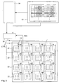
- FIG. 1 shows a perspective view of a data storage device.
- a storage medium 2 comprising a substrate 4 and a polymer layer 6 is facing a probe array 8 having a plurality of probes 10.
- the substrate 4 is preferably formed of silicon, the polymer layer 6 of a thin polymethylmethacrylate (PMMA) layer.
- Probes 10 are mechanically linked to a linking element 12 having the shape of a plate.
- the linking element 12 is transparent and cut open at one edge solely for demonstration purposes.
- Figure 3 shows a perspective view of a single probe 10.
- the probe comprises a spring cantilever 14 with a tip 16 at its end.
- the spring cantilever 14 is sensitive to vertical forces.
- the stiffness of the spring cantilever 14 in a lateral direction is much higher than in the vertical direction.
- the tip 16 is conically-shaped and has a decreasing diameter towards its apex 18.
- the apex 18 has preferably a radius of only a few nanometers. Ideally only one atom forms the apex 18 of the tip 16.
- the probe 10 further comprises a heater platform 20 between legs of the spring cantilever 14 and the tip 16.
- the probe 10 further may comprise a first electrode 22, that acts together with a second electrode 24 formed in or on the storage medium forming a capacitor. Depending on the charge of this capacitor a force acting vertically to the surface of the storage medium 2 can be applied on the spring cantilever 14.
- the spring cantilever 14 is preferably fabricated entirely of silicon for good thermal and mechanical stability.
- the legs of the spring cantilever 14 are preferably highly doped in order to minimize their electrical resistance as they also serve the purpose of an electrical connection to the heater platform 20, the heater platform has a high electrical resistance of, for example, 11 kilo Ohms. The legs also serve the purpose of an electrical connection to the first electrode 22.
- Indentation marks 28 are created on the storage medium 2 using a thermomechanical technique. A local force is applied to the polymer layer 6 by the probe 10. The polymer layer 6 is softened by heating the heater platform 20 with a current or voltage pulse during the contact mode, so that the polymer layer 6 is softened locally where the tip 16 touches the polymer layer 6. The result is a small indentation mark 28 in the polymer layer (see FIG. 4 ) having a nanoscale diameter.
- the indentation marks 28 represent binary information. For example, an indentation mark may represent a logical "1" and the absence of the indentation mark 28 may represent a logical "0". However, the indentation mark 28 or an absence of the indentation mark 28 may also represent a different information, for example the presence of the indentation mark 28 may represent a logical "0" and the absence of the indentation mark 28 may represent a logical "1".
- the polymer layer 6 is moved under the probe array 8 at a constant velocity.
- the scanning velocity and the distance between the indentation marks 28 determine the data rate of the system in indentation marks 28 or bits read or written per second. Reading is also accomplished with a thermomechanical concept.
- the heater platform 20 is operated at a temperature, that is not high enough to soften the polymer layer 6 as is necessary for writing.
- the thermal sensing is based on the fact that the thermal conductance between the probe 10, in particular the heater platform 20 and the tip 16, and the storage medium 2 changes when the tip 16 is moving into an indentation mark 28 where the distance between the heater platform 20 and the polymer layer 6 is reduced.
- the temperature change of the heater platform 20 is gradual as it moves towards the center of the indentation mark 28, where the indentation mark's 28 depth is maximum. Consequently the resistance of the heater platform 20 decreases at the same time. Thus changes in the resistance of the heater platform 20 may be monitored while the probe 10 is scanned over indentation marks 28.
- indentation marks 28 are shown only in a confined area of the storage medium 2 back in Figure 1 .
- the probes 10 are suited for scanning the entire storage medium 2 either by moving the probe array 8 relatively to a storage medium 2 or vice versa.
- the storage medium 2 is moved while the probe array 8 is fixed in its position.
- Arrows X and Y indicate the scanning direction, while Z arrows indicate an approaching and leveling scheme in vertical direction for bringing the entire probe array 8 into contact with the storage medium 2.
- the storage device comprises a respective drive 36, the drive 36 comprises respective actuators, for example electromagnetic or piezoelectric actuators by means of which actuation in each direction is precisely achieved.
- the drive may also only act on the X and Y scanning direction, with the approaching and leveling scheme in vertical direction being accomplished by controlling the charge of the capacitor comprising the first and second electrode 22, 24.
- the storage medium 2 is divided into fields, not explicitly shown in Figure 1 .
- Each probe 10 of the probe array 8 writes or reads only in its own data field. Consequently a storage device with, for example 32 x 32 probes includes 1024 fields.
- the storage device is preferentially operated with row and column time-multiplexing addressing, schematically shown by multiplexers 30, 31.
- the storage device according to Figure 1 is ready for parallel scanning of all fields. Storage fields might also be scanned row by row or column by column. Every movement of a single probe 10 in the X, Y direction is applied to all the other probes 10 due to mechanical coupling of the probes 10.
- Figure 2 represents a symbolic top view of the storage medium 2 with 4 x 4 fields 32 arranged in rows and columns.
- Each field 32 comprises indentation marks 28.
- the fields 32 are bordered in order to make them visible. Such borders in forms of grooves might also be placed on the storage medium 2 for defining the beginning and the end of a field 32, but this is not necessarily the case. Rather fields 32 are defined by the extent of indentation marks 28 a single probe 10 is responsible for.
- probes 10 are electrically connected with the multiplexers 30, 31, which are preferentially time multiplexers. Their connection with the multiplexers 30, 31 is represented symbolically with common wires in Figure 2 . In case the probes 10 are equipped with first electrodes 22 there are separate electrical connections to the multiplexers 30,31 for connecting the first electrodes 22 apart from the heater platforms 20.
- a control unit 34 is designed for creating control parameter CTRL acting on the probes 10 and resulting in a creation of indentation marks 28. It is further designed for controlling a read-back procedure, by which the information stored on the storage medium 2, represented by indentation marks or the absence of indentation marks 28 is read back RES and is also designed for processing this read back information.
- a first coding unit 40 which receives information data during the operation of the data storage device, this information data is preferably in a binary coded form, that means the information consists of a sequence of logical "1" and logical "0". It is assumed that a logical "1" corresponds to forming an indentation mark while a logical "0" indicates the absence of forming an indentation mark 28. However, if a logical "0" corresponds to an indentation mark 28 and a logical "1" corresponds to the absence of the indentation mark 28 the following disclosure applies respectively.
- the first coding unit 40 codes the received information, which is of a binary coded type, by applying so-called (d,k)-codes.
- d denotes a minimum number of consecutive logical "0"s placed between consecutive logical "1”s in a code series.
- k denotes a maximum number of consecutive logical "0"s placed between consecutive logical "1”s in a code series.
- (d,k)-codes are disclosed in " Codes for Mass Data Storage Systems” by Kees A.S. Immink, Shannon Foundation Publishers, Rotterdam, The Netherlands, 1999 .
- Such (d,k)-codes are further disclosed in US patent number 6 340 938 , which is incorporated by reference for this purpose.
- a (d,k)-code disclosed therein is a (1,7)-code with an additional constraint of a limit value of 5 and a rate of two-thirds. Coding the information data with such a code has the advantage that the equivalent distance between two consecutive indentation marks 28, representing logical "1"'s may be reduced respectively.
- two consecutive indentation marks placed at the minimum possible distance apart from each other are represented by the bit sequence 11.
- bit sequence 101 In the case of a (1,7) (d,k) code such consecutive two indentation marks placed at the minimum possible distance apart from each other are represented by the bit sequence 101. In that way the physical nominal distance between two consecutive coded bits may be halved.
- the first coding unit 40 preferably comprises a look-up table, part of an example of which is schematically shown in FIG. 2 inside the block showing the first control unit 40.
- the coded information is then either directly transmitted to the control unit 34 or it may also be an input to a further, a second coding unit 38.
- the second coding unit 38 may either receive information in a coded form from the first coding unit 40 or it may receive uncoded data information.
- the second coding unit 38 limits the number of consecutive logical "1"s, in case of uncoded data input or "01”s in case of (1,7) (d,k) coded data input or "001" or "0001” and so on in case of other coded data input to a given limit value. Codes being suitable for that purpose are called constrained codes.
- the limit value is preferably chosen between 5 and 7, most preferably 7.
- the limit value may be chosen in accordance with a minimum nominal distance between two consecutive indentation marks 28. The smaller this nominal minimum distance is the smaller the limit value should be chosen. However the limit value may also be chosen appropriately depending on the embodiment of a program being processed in the control unit 34 and controlling the creation of indentation marks and the way the respective parameters of the program are chosen.
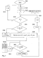
- a program which is processed during the operation of the data storage device in the control unit 34 is described in the following with the aid of the flow chart of FIG. 5 .
- the program is started in a step S1.
- this step preferably variables are initialized.
- a counter k is initialized with a value of one.
- a number n of consecutive indentation marks 28 to be created is determined by counting the number of consecutive logical "1"s or "01”s or "001"s depending on the coding applied in the first coding unit 40 of the current input data string received from the first or the second coding unit 38, 40 or from another unit possibly in an uncoded way.
- step S6 it is determined whether the counter k is greater than the number n of consecutive indentation marks 28 to be created. If this is the case the program proceeds to a step S7, where the program rests for a given duration of time T_W before it proceeds again to step S2.
- the given duration T_W of time is chosen appropriately in order to ensure, that each information bit is processed appropriately.
- step S8 it is checked whether the number n of consecutive indentation marks 28 to be created is larger or equal to a given number n_thr of consecutive indentation marks to be created.
- the given number n_thr of consecutive indentation marks 28 to be created is preferably chosen with a value of 2.
- step S8 the program proceeds to a step S10, in which a point of time t_create for creating a control parameter CTRL is set to a nominal point of time t_nom for the respective current counter value k.
- the nominal point of time t_nom may be chosen for example in a range, that two consecutive creation events of creating the control parameter CTRL are spaced apart 360 microseconds.
- step S12 a shift s for the respective value of the counter k is determined according to the relation shown in step S12, where s_min denotes a minimum shift and s_max denotes a maximum shift.
- the given minimum shift s_min has preferably a negative value, whereas the given maximum shift s_max has preferably a positive value.
- a given maximum shift s_max and the given minimum shift s_min preferably have the same absolute value but their absolute values may also differ from each other.
- the absolute values of the given maximum shift s_max and the given minimum shift s_min preferably are in the range of just a small fraction of the nominal minium time interval between two consecutive creations of indentation marks 28. They may be in the range of one-sixth of this time.
- the relation for determining the shift s for the current value of the counter k has a linear course. It may alternatively also have a course with a progressively decreasing absolute value of the shift s towards the middle of the number n of consecutive indentation marks 28 to be created and then from the middle on again having a progressively increasing absolute value of the respective shift s.
- a course of the shift may in this case also be symmetric to the middle of its course, that is the value of the counter k being equal to n/2.
- the shift s corresponding to the indentation mark to be created in the middle of consecutive indentation marks 28 to be created has preferably an absolute value in the range of zero.
- the shift corresponding to the counter k equal to (n-1) divided by 2 or (n+1) divided by 2 preferably has the shift s with the smallest absolute value.
- the program proceeds after the step S12 to a step S14 where the point of time t_create for creating the control parameter CTRL is set to the nominal point of time t_nom for creating the control parameter CTRL for the current value of the counter k plus the current shift s determined in step 12 divided by a velocity v of the probe 10 relative to the storage medium 2 in an x or y direction.
- step S16 After that in a step S16 it is evaluated, whether the current point of time t is the point of time t_create for creating the control parameter CTRL. If the condition of step S16 is not fulfilled then the program proceeds to a step S17, where it rests for the given duration of time T_W before the condition of step S16 is again evaluated. The given duration of time T_W is suitably chosen. If however, the condition of step S16 is fulfilled the program proceeds to a step S18 where the control parameter CTRL is created.
- the control parameter may for example be a voltage pulse affecting the heater platform 20 and in that way heating the heater platform 20. It may also be a respective current pulse affecting the heater platform 20. It may also be a current or voltage pulse affecting the first electrode 22 or respectively the second electrode 24.
- control parameter CTRL preferably always has the same value when it is created.
- the program proceeds to a step S19 where the counter k is incremented by one.
- the program proceeds to a step S20, where the program rests for the given duration of time T_W before it proceeds again to step S6.
- the given duration T_W of time is chosen appropriately in order to ensure, that each information bit is processed appropriately.
- FIG. 6 shows a second embodiment of the program which is processed in the control unit 34 during the operation of the storage device.
- the steps S22, S24, S26, S28, S29, S30,S32 and S43 correspond to the steps of FIG. 5 , S1,S2, S4, S6, S7, S20, S8 and S19.
- step S34 a force F corresponding to the current value of the counter k is assigned a nominal value F_nom of the force. If, however, the condition of the step S32 is fulfilled, then the force F for the current value of the counter k is assigned a value determined depending on the relation shown in the step S36.
- F_max denotes a maximum force
- F_min denotes a minimum force.
- the force in general is the force exerted by the tip 16 on the polymer layer 6 while the control parameter is created.
- the minimum force F_min is predetermined taking into consideration noise margin issues based on an average read-back amplitude of isolated indentation marks 28, that means indentation marks, that are not spaced at the given minimum distance from other adjacent indentation marks, but of at least twice that distance.
- the given minimum distance might be, for example, 35 nm.
- Such isolated indentation marks 28 typically result during a reading operation in a read-back amplitude which typically is above a certain threshold for a given amount of noise in the read-back signal.
- the maximum force F_max may be limited by influencing factors such as wear of tip 16 or the feasibility of the generation of respectively high voltage pulses in a driver incorporated in the control unit.
- step S36 results in a linear reduction of the force F with an increasing value of the counter k. In that way partial erasing between consecutive indentation marks 28 is effectively reduced.
- the relation of the step S36 may also have another course. It is only essential that the amount of applied force is gradually decreasing.
- step S40 the program proceeds to a step S40 where it evaluates whether the current point of time t equals the nominal point t_nom of time corresponding to the current value of the counter k. If this is not the case the program proceeds to a step S41, where it rests for the given duration T_W of time before it proceeds again to the step S40. If the condition of the step S40 is fulfilled then the program proceeds to a step S42 in which it creates the control parameter CTRL corresponding to the current value of the force F for the current value of the counter k.
- the control parameter may be assigned to the current force F via a look-up table.
- the control parameter CTRL is preferably a current or voltage pulse affecting the first or the second electrode 22, 24.
- step S43 the counter k is incremented by one. After the step S43 the program proceeds to the step S30.
- the force F for the current value of the counter k may be determined in an alternative step S36a by the use of, for example, a look-up table with given values of the force F corresponding to the values of the counter k. For example a given first force F1 is assigned if the current value of the counter k equals 1. The same applies respectively for a second force F2 which is assigned, if the current value of the counter equals 2 and a third force F3 is assigned if the current value of the counter equals 3.
- a third embodiment of the program, which is processed in the control unit 34 is shown by the aid of the flow chart of FIG. 7 .
- the flow chart of FIG. 7 basically corresponds to the flow chart of FIG. 6 with the steps S44, S46, S48, S50, S51, S52, S54, S62, S63 and S65 corresponding to the steps S22, S24, S26, S28, S29, S30, S32, S40, S41 and S43.
- the step S56 respectively corresponds to the step S34 with the difference that instead of the force a heating power P for the current value of the counter k is assigned a nominal heating power P_nom which is predetermined.
- P_nom a nominal heating power
- P_min a minimum heating power.
- the maximum heating power P_max and the minimum P_min are predetermined taking into consideration the same constraints which apply for the maximum force F_max and the minimum force F_min as in step S36 of FIG. 6 .
- control parameter CTRL affects in this case preferably the heater platform 20.
- the control parameter is in this case preferably either a voltage or a current pulse.
- step S58a may be processed, which incorporates a respective look-up table as in step S36a with the difference that in this case respective values of the heating power P are assigned depending on the value of the counter k.
- a first given heating power P1 is assigned if the counter k has a value of 1
- a second given heating power P2 is assigned if the counter k has a value of 2
- a third given heating power P3 is assigned if the counter k has a value of 3.
- the conditions that these given first to third heating powers P1 to P3 and possibly further given heating powers need to fulfill are identical to the conditions described above for the forces F1 to F3 and possibly further given forces.
- the control unit 34 If the information data received by the control unit 34 is coded in the first coding unit by applying a (d,k)-code then the counter n counts consecutive patterns of(0 1) or (1 0) in the case of d being 1. All the steps in the disclosed embodiments of the program are applied then in a respective matter.
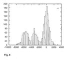
- FIG. 8 shows a histogram of read-back samples without modifying the control parameter CTRL, if a given number of consecutive indentation marks 28 should be created.
- the histogram according to FIG. 8 shows that in this case there is a large number of samples which cannot be clearly allocated to either corresponding to an indentation mark 28 or to not corresponding to an indentation mark.
- the x-axis of the histogram denotes the amplitude of the respective read-back signal whereas the ordinate denotes the amounts of samples allocated to the respective amplitude value of a read-back signal.
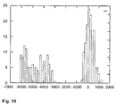
- FIG. 9 shows a histogram of read-back samples employing the first embodiment of the program according to FIG. 6 . In this there are clearly separated bins of samples. If a threshold determining whether a read-back sample corresponds to an indentation mark or not has the value of-2000 then there is a clear separation between indentation marks 28 and the absence of indentation marks.
- FIG. 10 shows another histogram of read-back samples employing the program of the first embodiment with an even clearer separation between the two bins.
Landscapes
- Engineering & Computer Science (AREA)
- Chemical & Material Sciences (AREA)
- Nanotechnology (AREA)
- Physics & Mathematics (AREA)
- Mathematical Physics (AREA)
- Theoretical Computer Science (AREA)
- Crystallography & Structural Chemistry (AREA)
- Read Only Memory (AREA)
- Semiconductor Memories (AREA)
- Optical Recording Or Reproduction (AREA)
- Signal Processing For Digital Recording And Reproducing (AREA)
- Memory System Of A Hierarchy Structure (AREA)
Priority Applications (1)
| Application Number | Priority Date | Filing Date | Title |
|---|---|---|---|
| EP05754234A EP1759389B1 (en) | 2004-06-22 | 2005-06-21 | Data storage device and method for operating a data storage device |
Applications Claiming Priority (3)
| Application Number | Priority Date | Filing Date | Title |
|---|---|---|---|
| EP04405387 | 2004-06-22 | ||
| EP05754234A EP1759389B1 (en) | 2004-06-22 | 2005-06-21 | Data storage device and method for operating a data storage device |
| PCT/IB2005/001733 WO2006000872A1 (en) | 2004-06-22 | 2005-06-21 | Data storage device and method for operating a data storage device |
Publications (2)
| Publication Number | Publication Date |
|---|---|
| EP1759389A1 EP1759389A1 (en) | 2007-03-07 |
| EP1759389B1 true EP1759389B1 (en) | 2008-05-21 |
Family
ID=35033557
Family Applications (1)
| Application Number | Title | Priority Date | Filing Date |
|---|---|---|---|
| EP05754234A Expired - Lifetime EP1759389B1 (en) | 2004-06-22 | 2005-06-21 | Data storage device and method for operating a data storage device |
Country Status (7)
| Country | Link |
|---|---|
| US (3) | US8107353B2 (https=) |
| EP (1) | EP1759389B1 (https=) |
| JP (1) | JP4538499B2 (https=) |
| CN (1) | CN100557690C (https=) |
| AT (1) | ATE396479T1 (https=) |
| DE (1) | DE602005007023D1 (https=) |
| WO (1) | WO2006000872A1 (https=) |
Families Citing this family (13)
| Publication number | Priority date | Publication date | Assignee | Title |
|---|---|---|---|---|
| US7260051B1 (en) | 1998-12-18 | 2007-08-21 | Nanochip, Inc. | Molecular memory medium and molecular memory integrated circuit |
| TW571291B (en) * | 2001-01-31 | 2004-01-11 | Ibm | Mechanical data processing |
| US7233517B2 (en) | 2002-10-15 | 2007-06-19 | Nanochip, Inc. | Atomic probes and media for high density data storage |
| WO2006000872A1 (en) * | 2004-06-22 | 2006-01-05 | International Business Machines Corporation | Data storage device and method for operating a data storage device |
| US7367119B2 (en) | 2005-06-24 | 2008-05-06 | Nanochip, Inc. | Method for forming a reinforced tip for a probe storage device |
| US7463573B2 (en) | 2005-06-24 | 2008-12-09 | Nanochip, Inc. | Patterned media for a high density data storage device |
| US7309630B2 (en) | 2005-07-08 | 2007-12-18 | Nanochip, Inc. | Method for forming patterned media for a high density data storage device |
| US20070286996A1 (en) * | 2006-05-30 | 2007-12-13 | International Business Machines Corporation | Data storage device and method of production therefor |
| WO2007146504A2 (en) * | 2006-06-15 | 2007-12-21 | Nanochip, Inc. | Cantilever with control of vertical and lateral position of contact probe tip |
| US8023393B2 (en) * | 2007-05-10 | 2011-09-20 | International Business Machines Corporation | Method and apparatus for reducing tip-wear of a probe |
| US7889627B2 (en) * | 2007-11-05 | 2011-02-15 | Seagate Technology Llc | Preload modulation to reduce head motion hysteresis |
| US8264941B2 (en) * | 2007-12-26 | 2012-09-11 | Intel Corporation | Arrangement and method to perform scanning readout of ferroelectric bit charges |
| KR102253995B1 (ko) * | 2013-03-12 | 2021-05-18 | 마이크로닉 아베 | 기계적으로 생성된 정렬 표식 방법 및 정렬 시스템 |
Family Cites Families (18)
| Publication number | Priority date | Publication date | Assignee | Title |
|---|---|---|---|---|
| CH643397A5 (de) | 1979-09-20 | 1984-05-30 | Ibm | Raster-tunnelmikroskop. |
| US4637865A (en) | 1985-08-16 | 1987-01-20 | Great Lakes Chemical Corporation | Process for metal recovery and compositions useful therein |
| JP2615650B2 (ja) | 1987-08-17 | 1997-06-04 | 松下電器産業株式会社 | 光学情報記録部材の記録方法 |
| DE69232806T2 (de) * | 1991-07-17 | 2003-02-20 | Canon K.K., Tokio/Tokyo | Informationsaufzeichnungs-/-wiedergabegerät oder -verfahren zur Informationsaufzeichnung/- wiedergabe auf/von einem Informationsaufzeichnungsmedium unter Verwendung einer Vielzahl von Sondenelektroden |
| JP3576644B2 (ja) * | 1995-06-19 | 2004-10-13 | キヤノン株式会社 | 情報記録装置のプローブ及び記録媒体、並びにこれらを用いた情報記録方法 |
| JPH09120593A (ja) * | 1995-08-23 | 1997-05-06 | Sony Corp | 記録再生装置 |
| JP3235786B2 (ja) * | 1998-06-30 | 2001-12-04 | 技術研究組合オングストロームテクノロジ研究機構 | 走査プローブの力制御方法 |
| US6884999B1 (en) * | 2000-10-24 | 2005-04-26 | Advanced Micro Devices, Inc. | Use of scanning probe microscope for defect detection and repair |
| TW550622B (en) * | 2000-11-03 | 2003-09-01 | Ibm | Data storage device and read/write component for data storage device |
| TW571291B (en) | 2001-01-31 | 2004-01-11 | Ibm | Mechanical data processing |
| TWI244619B (en) * | 2001-03-23 | 2005-12-01 | Ibm | Data read/write systems |
| US6692145B2 (en) * | 2001-10-31 | 2004-02-17 | Wisconsin Alumni Research Foundation | Micromachined scanning thermal probe method and apparatus |
| EP1372151B1 (en) * | 2002-05-13 | 2005-07-13 | International Business Machines Corporation | Data overwriting in probe-based data storage devices |
| JP3966514B2 (ja) * | 2002-05-23 | 2007-08-29 | インターナショナル・ビジネス・マシーンズ・コーポレーション | 記憶装置、および記憶装置を操作する方法 |
| CN100383874C (zh) * | 2002-11-28 | 2008-04-23 | 国际商业机器公司 | 在基于探针的数据存储器件中的数据重写的方法和装置 |
| US7463572B2 (en) * | 2003-08-29 | 2008-12-09 | International Business Machines Corporation | High density data storage medium |
| US7257691B2 (en) * | 2003-09-26 | 2007-08-14 | International Business Machines Corporation | Writing and reading of data in probe-based data storage devices |
| WO2006000872A1 (en) * | 2004-06-22 | 2006-01-05 | International Business Machines Corporation | Data storage device and method for operating a data storage device |
-
2005
- 2005-06-21 WO PCT/IB2005/001733 patent/WO2006000872A1/en not_active Ceased
- 2005-06-21 CN CNB2005800082015A patent/CN100557690C/zh not_active Expired - Lifetime
- 2005-06-21 US US11/630,879 patent/US8107353B2/en not_active Expired - Fee Related
- 2005-06-21 DE DE602005007023T patent/DE602005007023D1/de not_active Expired - Lifetime
- 2005-06-21 EP EP05754234A patent/EP1759389B1/en not_active Expired - Lifetime
- 2005-06-21 JP JP2007517514A patent/JP4538499B2/ja not_active Expired - Fee Related
- 2005-06-21 AT AT05754234T patent/ATE396479T1/de not_active IP Right Cessation
- 2005-06-22 US US11/158,844 patent/US7522511B2/en not_active Expired - Fee Related
-
2008
- 2008-05-26 US US12/126,956 patent/US7675837B2/en not_active Expired - Fee Related
Also Published As
| Publication number | Publication date |
|---|---|
| ATE396479T1 (de) | 2008-06-15 |
| EP1759389A1 (en) | 2007-03-07 |
| US7675837B2 (en) | 2010-03-09 |
| CN1930624A (zh) | 2007-03-14 |
| US20050281174A1 (en) | 2005-12-22 |
| US20080225676A1 (en) | 2008-09-18 |
| JP4538499B2 (ja) | 2010-09-08 |
| WO2006000872A1 (en) | 2006-01-05 |
| US8107353B2 (en) | 2012-01-31 |
| US7522511B2 (en) | 2009-04-21 |
| DE602005007023D1 (de) | 2008-07-03 |
| JP2008503842A (ja) | 2008-02-07 |
| US20100265812A1 (en) | 2010-10-21 |
| CN100557690C (zh) | 2009-11-04 |
Similar Documents
| Publication | Publication Date | Title |
|---|---|---|
| EP1759389B1 (en) | Data storage device and method for operating a data storage device | |
| JP4099100B2 (ja) | 記憶装置、および記憶媒体を走査する方法 | |
| Lutwyche et al. | Highly parallel data storage system based on scanning probe arrays | |
| EP1530210B1 (en) | Information recording/reproducing apparatus and recording medium | |
| US6665258B1 (en) | Method and apparatus for recording, storing and reproducing information | |
| EP0382062A2 (en) | Electronic circuits including atomic probe | |
| JP4435193B2 (ja) | プローブメモリ装置に搭載される位置決めシステムとその位置決め方法 | |
| WO1997044780A1 (en) | Shape memory alloy recording medium, storage devices based thereon, and method for using these storage devices | |
| WO2000036608A2 (en) | Molecular memory medium and molecular memory integrated circuit | |
| JP4642236B2 (ja) | 情報媒体の書込および読取方法、並びに記録媒体 | |
| JPH0575047A (ja) | 記憶装置 | |
| GB2411281A (en) | Nanotechnology Storage Device With Each Storage Cell Representing More Than One Data Bit | |
| CN100476967C (zh) | 数据读/写系统 | |
| US7085151B2 (en) | Storage device having a resistance measurement system | |
| US20050157575A1 (en) | Storage device and method | |
| KR100935619B1 (ko) | 데이터 저장 장치 및 데이터 저장 장치를 작동하는 방법 | |
| JP4979229B2 (ja) | 基板に亘って走査するプローブ | |
| Vettiger et al. | Thousands of microcantilevers for highly parallel and ultra-dense data storage | |
| US7876662B2 (en) | Recording in probe-based data storage devices | |
| EP1365395B1 (en) | Storage device and method for operating a storage device | |
| KR100881740B1 (ko) | 열팽창에 따른 에러보정이 가능한 나노정보저장장치 | |
| US20080230696A1 (en) | Surface treatment and surface scanning | |
| Despont et al. | Thousands of Micro-Cantilevers for Highly Parallel and Ultra-dense Probe Data Storage | |
| JPH09147433A (ja) | 情報記録再生方法およびその装置 | |
| Despont et al. | A highly parrallel probe-based storage system |
Legal Events
| Date | Code | Title | Description |
|---|---|---|---|
| PUAI | Public reference made under article 153(3) epc to a published international application that has entered the european phase |
Free format text: ORIGINAL CODE: 0009012 |
|
| 17P | Request for examination filed |
Effective date: 20061130 |
|
| AK | Designated contracting states |
Kind code of ref document: A1 Designated state(s): AT BE BG CH CY CZ DE DK EE ES FI FR GB GR HU IE IS IT LI LT LU MC NL PL PT RO SE SI SK TR |
|
| 17Q | First examination report despatched |
Effective date: 20070411 |
|
| DAX | Request for extension of the european patent (deleted) | ||
| GRAP | Despatch of communication of intention to grant a patent |
Free format text: ORIGINAL CODE: EPIDOSNIGR1 |
|
| GRAS | Grant fee paid |
Free format text: ORIGINAL CODE: EPIDOSNIGR3 |
|
| GRAA | (expected) grant |
Free format text: ORIGINAL CODE: 0009210 |
|
| AK | Designated contracting states |
Kind code of ref document: B1 Designated state(s): AT BE BG CH CY CZ DE DK EE ES FI FR GB GR HU IE IS IT LI LT LU MC NL PL PT RO SE SI SK TR |
|
| REG | Reference to a national code |
Ref country code: GB Ref legal event code: FG4D |
|
| REG | Reference to a national code |
Ref country code: CH Ref legal event code: NV Representative=s name: IBM RESEARCH GMBH ZURICH RESEARCH LABORATORY INTEL Ref country code: CH Ref legal event code: EP Ref country code: GB Ref legal event code: 746 Effective date: 20080529 |
|
| REF | Corresponds to: |
Ref document number: 602005007023 Country of ref document: DE Date of ref document: 20080703 Kind code of ref document: P |
|
| REG | Reference to a national code |
Ref country code: IE Ref legal event code: FG4D |
|
| PG25 | Lapsed in a contracting state [announced via postgrant information from national office to epo] |
Ref country code: SI Free format text: LAPSE BECAUSE OF FAILURE TO SUBMIT A TRANSLATION OF THE DESCRIPTION OR TO PAY THE FEE WITHIN THE PRESCRIBED TIME-LIMIT Effective date: 20080521 |
|
| PG25 | Lapsed in a contracting state [announced via postgrant information from national office to epo] |
Ref country code: FI Free format text: LAPSE BECAUSE OF FAILURE TO SUBMIT A TRANSLATION OF THE DESCRIPTION OR TO PAY THE FEE WITHIN THE PRESCRIBED TIME-LIMIT Effective date: 20080521 Ref country code: ES Free format text: LAPSE BECAUSE OF FAILURE TO SUBMIT A TRANSLATION OF THE DESCRIPTION OR TO PAY THE FEE WITHIN THE PRESCRIBED TIME-LIMIT Effective date: 20080901 |
|
| NLV1 | Nl: lapsed or annulled due to failure to fulfill the requirements of art. 29p and 29m of the patents act | ||
| PG25 | Lapsed in a contracting state [announced via postgrant information from national office to epo] |
Ref country code: PL Free format text: LAPSE BECAUSE OF FAILURE TO SUBMIT A TRANSLATION OF THE DESCRIPTION OR TO PAY THE FEE WITHIN THE PRESCRIBED TIME-LIMIT Effective date: 20080521 Ref country code: NL Free format text: LAPSE BECAUSE OF FAILURE TO SUBMIT A TRANSLATION OF THE DESCRIPTION OR TO PAY THE FEE WITHIN THE PRESCRIBED TIME-LIMIT Effective date: 20080521 Ref country code: AT Free format text: LAPSE BECAUSE OF FAILURE TO SUBMIT A TRANSLATION OF THE DESCRIPTION OR TO PAY THE FEE WITHIN THE PRESCRIBED TIME-LIMIT Effective date: 20080521 |
|
| PG25 | Lapsed in a contracting state [announced via postgrant information from national office to epo] |
Ref country code: IS Free format text: LAPSE BECAUSE OF FAILURE TO SUBMIT A TRANSLATION OF THE DESCRIPTION OR TO PAY THE FEE WITHIN THE PRESCRIBED TIME-LIMIT Effective date: 20080921 |
|
| PG25 | Lapsed in a contracting state [announced via postgrant information from national office to epo] |
Ref country code: SE Free format text: LAPSE BECAUSE OF FAILURE TO SUBMIT A TRANSLATION OF THE DESCRIPTION OR TO PAY THE FEE WITHIN THE PRESCRIBED TIME-LIMIT Effective date: 20080821 Ref country code: MC Free format text: LAPSE BECAUSE OF NON-PAYMENT OF DUE FEES Effective date: 20080630 Ref country code: LT Free format text: LAPSE BECAUSE OF FAILURE TO SUBMIT A TRANSLATION OF THE DESCRIPTION OR TO PAY THE FEE WITHIN THE PRESCRIBED TIME-LIMIT Effective date: 20080521 Ref country code: DK Free format text: LAPSE BECAUSE OF FAILURE TO SUBMIT A TRANSLATION OF THE DESCRIPTION OR TO PAY THE FEE WITHIN THE PRESCRIBED TIME-LIMIT Effective date: 20080521 Ref country code: CZ Free format text: LAPSE BECAUSE OF FAILURE TO SUBMIT A TRANSLATION OF THE DESCRIPTION OR TO PAY THE FEE WITHIN THE PRESCRIBED TIME-LIMIT Effective date: 20080521 |
|
| PG25 | Lapsed in a contracting state [announced via postgrant information from national office to epo] |
Ref country code: SK Free format text: LAPSE BECAUSE OF FAILURE TO SUBMIT A TRANSLATION OF THE DESCRIPTION OR TO PAY THE FEE WITHIN THE PRESCRIBED TIME-LIMIT Effective date: 20080521 Ref country code: RO Free format text: LAPSE BECAUSE OF FAILURE TO SUBMIT A TRANSLATION OF THE DESCRIPTION OR TO PAY THE FEE WITHIN THE PRESCRIBED TIME-LIMIT Effective date: 20080521 Ref country code: PT Free format text: LAPSE BECAUSE OF FAILURE TO SUBMIT A TRANSLATION OF THE DESCRIPTION OR TO PAY THE FEE WITHIN THE PRESCRIBED TIME-LIMIT Effective date: 20081021 Ref country code: BE Free format text: LAPSE BECAUSE OF FAILURE TO SUBMIT A TRANSLATION OF THE DESCRIPTION OR TO PAY THE FEE WITHIN THE PRESCRIBED TIME-LIMIT Effective date: 20080521 |
|
| PLBE | No opposition filed within time limit |
Free format text: ORIGINAL CODE: 0009261 |
|
| STAA | Information on the status of an ep patent application or granted ep patent |
Free format text: STATUS: NO OPPOSITION FILED WITHIN TIME LIMIT |
|
| 26N | No opposition filed |
Effective date: 20090224 |
|
| PG25 | Lapsed in a contracting state [announced via postgrant information from national office to epo] |
Ref country code: IE Free format text: LAPSE BECAUSE OF NON-PAYMENT OF DUE FEES Effective date: 20080621 Ref country code: EE Free format text: LAPSE BECAUSE OF FAILURE TO SUBMIT A TRANSLATION OF THE DESCRIPTION OR TO PAY THE FEE WITHIN THE PRESCRIBED TIME-LIMIT Effective date: 20080521 Ref country code: BG Free format text: LAPSE BECAUSE OF FAILURE TO SUBMIT A TRANSLATION OF THE DESCRIPTION OR TO PAY THE FEE WITHIN THE PRESCRIBED TIME-LIMIT Effective date: 20080821 |
|
| PG25 | Lapsed in a contracting state [announced via postgrant information from national office to epo] |
Ref country code: IT Free format text: LAPSE BECAUSE OF FAILURE TO SUBMIT A TRANSLATION OF THE DESCRIPTION OR TO PAY THE FEE WITHIN THE PRESCRIBED TIME-LIMIT Effective date: 20080521 |
|
| REG | Reference to a national code |
Ref country code: CH Ref legal event code: PL |
|
| PG25 | Lapsed in a contracting state [announced via postgrant information from national office to epo] |
Ref country code: LI Free format text: LAPSE BECAUSE OF NON-PAYMENT OF DUE FEES Effective date: 20090630 Ref country code: CH Free format text: LAPSE BECAUSE OF NON-PAYMENT OF DUE FEES Effective date: 20090630 |
|
| PG25 | Lapsed in a contracting state [announced via postgrant information from national office to epo] |
Ref country code: LU Free format text: LAPSE BECAUSE OF NON-PAYMENT OF DUE FEES Effective date: 20080621 Ref country code: HU Free format text: LAPSE BECAUSE OF FAILURE TO SUBMIT A TRANSLATION OF THE DESCRIPTION OR TO PAY THE FEE WITHIN THE PRESCRIBED TIME-LIMIT Effective date: 20081122 Ref country code: CY Free format text: LAPSE BECAUSE OF FAILURE TO SUBMIT A TRANSLATION OF THE DESCRIPTION OR TO PAY THE FEE WITHIN THE PRESCRIBED TIME-LIMIT Effective date: 20080521 |
|
| PG25 | Lapsed in a contracting state [announced via postgrant information from national office to epo] |
Ref country code: TR Free format text: LAPSE BECAUSE OF FAILURE TO SUBMIT A TRANSLATION OF THE DESCRIPTION OR TO PAY THE FEE WITHIN THE PRESCRIBED TIME-LIMIT Effective date: 20080521 |
|
| PG25 | Lapsed in a contracting state [announced via postgrant information from national office to epo] |
Ref country code: GR Free format text: LAPSE BECAUSE OF FAILURE TO SUBMIT A TRANSLATION OF THE DESCRIPTION OR TO PAY THE FEE WITHIN THE PRESCRIBED TIME-LIMIT Effective date: 20080822 |
|
| PGFP | Annual fee paid to national office [announced via postgrant information from national office to epo] |
Ref country code: FR Payment date: 20110630 Year of fee payment: 7 |
|
| REG | Reference to a national code |
Ref country code: FR Ref legal event code: ST Effective date: 20130228 |
|
| PG25 | Lapsed in a contracting state [announced via postgrant information from national office to epo] |
Ref country code: FR Free format text: LAPSE BECAUSE OF NON-PAYMENT OF DUE FEES Effective date: 20120702 |
|
| REG | Reference to a national code |
Ref country code: DE Ref legal event code: R082 Ref document number: 602005007023 Country of ref document: DE Representative=s name: KUISMA, SIRPA, FI |
|
| PGFP | Annual fee paid to national office [announced via postgrant information from national office to epo] |
Ref country code: DE Payment date: 20220614 Year of fee payment: 18 |
|
| P01 | Opt-out of the competence of the unified patent court (upc) registered |
Effective date: 20230423 |
|
| REG | Reference to a national code |
Ref country code: DE Ref legal event code: R119 Ref document number: 602005007023 Country of ref document: DE |
|
| PG25 | Lapsed in a contracting state [announced via postgrant information from national office to epo] |
Ref country code: DE Free format text: LAPSE BECAUSE OF NON-PAYMENT OF DUE FEES Effective date: 20240103 |
|
| PGFP | Annual fee paid to national office [announced via postgrant information from national office to epo] |
Ref country code: GB Payment date: 20240626 Year of fee payment: 20 |
|
| PG25 | Lapsed in a contracting state [announced via postgrant information from national office to epo] |
Ref country code: GB Free format text: LAPSE BECAUSE OF EXPIRATION OF PROTECTION Effective date: 20250620 |
|
| REG | Reference to a national code |
Ref country code: GB Ref legal event code: PE20 Expiry date: 20250620 |