EP1759080B1 - Door holder for vehicle doors - Google Patents
Door holder for vehicle doors Download PDFInfo
- Publication number
- EP1759080B1 EP1759080B1 EP05767975A EP05767975A EP1759080B1 EP 1759080 B1 EP1759080 B1 EP 1759080B1 EP 05767975 A EP05767975 A EP 05767975A EP 05767975 A EP05767975 A EP 05767975A EP 1759080 B1 EP1759080 B1 EP 1759080B1
- Authority
- EP
- European Patent Office
- Prior art keywords
- door
- section
- spring
- holding part
- latching
- Prior art date
- Legal status (The legal status is an assumption and is not a legal conclusion. Google has not performed a legal analysis and makes no representation as to the accuracy of the status listed.)
- Not-in-force
Links
Images


Classifications
-
- E—FIXED CONSTRUCTIONS
- E05—LOCKS; KEYS; WINDOW OR DOOR FITTINGS; SAFES
- E05C—BOLTS OR FASTENING DEVICES FOR WINGS, SPECIALLY FOR DOORS OR WINDOWS
- E05C17/00—Devices for holding wings open; Devices for limiting opening of wings or for holding wings open by a movable member extending between frame and wing; Braking devices, stops or buffers, combined therewith
- E05C17/02—Devices for holding wings open; Devices for limiting opening of wings or for holding wings open by a movable member extending between frame and wing; Braking devices, stops or buffers, combined therewith by mechanical means
- E05C17/04—Devices for holding wings open; Devices for limiting opening of wings or for holding wings open by a movable member extending between frame and wing; Braking devices, stops or buffers, combined therewith by mechanical means with a movable bar or equivalent member extending between frame and wing
- E05C17/12—Devices for holding wings open; Devices for limiting opening of wings or for holding wings open by a movable member extending between frame and wing; Braking devices, stops or buffers, combined therewith by mechanical means with a movable bar or equivalent member extending between frame and wing consisting of a single rod
- E05C17/20—Devices for holding wings open; Devices for limiting opening of wings or for holding wings open by a movable member extending between frame and wing; Braking devices, stops or buffers, combined therewith by mechanical means with a movable bar or equivalent member extending between frame and wing consisting of a single rod sliding through a guide
- E05C17/203—Devices for holding wings open; Devices for limiting opening of wings or for holding wings open by a movable member extending between frame and wing; Braking devices, stops or buffers, combined therewith by mechanical means with a movable bar or equivalent member extending between frame and wing consisting of a single rod sliding through a guide concealed, e.g. for vehicles
Definitions
- the present invention is based on the object to simplify a door holder of the described generic type structurally and thereby reduce the manufacturing and assembly costs as well as the total weight.
- An inventive door holder 1 consists on the one hand of a rigid, rod-shaped or strip-shaped door-tether 2 and on the other hand of a holding part 12.
- the tether 2 is at one end to an only partially indicated vehicle axle 4 articulated via a pivot bearing 6, d. H. pivotable about a pivot axis 8, fastened, while the holding part 12 in the region of a so-called door head of a likewise indicated only vehicle door 10 is to be fastened such that it is stationary relative to the door 10 (rigid).
- the tether 2 extends relatively movable through the holding part 12 and with its free, the pivot bearing 6 opposite end 14 with variable length movement over the holding part 12 also into a cavity of the door 10 into it.
- the holding part 12 has at least one latching element 18, which is acted upon by a force accumulator 20 in the direction of the tether 2 out with a spring force F and cooperates with locking points 22 of the tether 2.
- the holding part 12 also has a holding portion 24.
- the holding part 12 only has a single latching points 22 formed as recesses or recesses on only one longitudinal edge 28 of the catching strap 2 cooperating locking element 18.
- the holding part 12 additionally has an opposing abutment element 30 (see in particular FIGS. 8 to 10), which supports the tether 2 against the detent spring force F generated by the force accumulator 20.
- the abutment element 30 is arranged offset in the longitudinal direction of the tether 2 somewhat in the direction of its free end 14 with respect to the detent element 18.
- the spring portion 34 thus extends substantially parallel to the latching element 18 forming end portion 32 of the molding 26, wherein the connecting portion 36, the tether 2 crosses.
- the aforementioned abutment element 30 is in this case formed by a voltage applied to the tether 2 portion of the spring portion 34.
- acting as a torsion spring portion 34 is guided in its the lever-like connecting portion 36 proximate (upper) area in an abutment 38 against transversely directed to its longitudinal deflection movements.
- the abutment 38 of the other, the latching element 18 forming end portion 32 opposite end portion 40 of the wire-bending molding 26 is formed by this end portion 40 is bent like a loop, that it wraps around the spring portion 34 in its region to be supported. This is preferably done indirectly with an intermediate arrangement of an annular bearing part 42, which expediently consists of a suitable plastic.
- the holding portion 24 is formed of two sections of the wire-shaped part 26, namely two flat embossed or compressed portions 24 a and 24 b. These sections each have a threaded element 44 for the door-side attachment.
- each threaded member 44 is designed as a threaded bore, but it may alternatively be a set threaded bolt.
- the two sections 24a, 24b are connected to each other via an intermediate portion 46 of the molding 26.
- one (upper) section 24a merges into the anvil 38 and the other (lower) section 24b into the spring section 34.
- FIGS. 2 and 5 to 7 the attachment of the holding part 12 in the door head area in the vehicle door 10 by mounting screws 48, which engage through holes in the door panel into the threaded holes 44.
- the intermediate section 46 connecting the sections 24a, 24b of the holding section 24 directly to each other can be rectilinear in the area between two bends of approximately 90 ° (see the embodiments according to FIGS. 11 to 14, FIGS. 17 and 18 as well as FIGS. 21 to 26) ). However, in the embodiments according to FIGS. 1 to 10 and FIGS. 15 and 16 as well as 19 and 20, it is provided that the intermediate section 46 has a region 50 which is bent like a bead in the direction of the tether 2.
- the latching element 18 is advantageously arranged relative to the holding section 24 (or relative to the sections 24 a, 24 b) in such a manner that when mounted with the vehicle door 10 Connected state of the holding part 12, the locking element 18 in a outside of the vehicle door 10 between this and the vehicle's vertical 4 lying gap, ie in front of the so-called door head, is arranged. This is achieved by a corresponding bending shaping of the holding part 12.
- This advantageous feature contributes to a very short design of the tether 2.
- the holding part 12 has two opposing latching elements 18 with opposite directions of action.
- the two locking elements 18 then act together with latching points formed on opposite longitudinal edges of the tether (not shown).
- the two locking elements 18 are formed by two free, mutually substantially parallel end portions 32 of the molded part 26.
- Each locking element 18 is connected via an associated, the force accumulator 20 forming spring portion 34 with the holding portion 24 and one of the two sections 24a, 24b.
- each spring portion 34 acts as an elongated bending spring and / or as a torsion spring, depending on the bending waveform. This should be easy to understand on the basis of the illustrations.
- the latching element 18 thus has a superficial metal surface and the tether 2 in the area of the longitudinal edge 28 having the latching points 22 on the surface of a plastic, so that it is a metal in each case with sliding friction relative to one another Plastic mating acts.
- a superficial metal surface and the tether 2 in the area of the longitudinal edge 28 having the latching points 22 on the surface of a plastic, so that it is a metal in each case with sliding friction relative to one another Plastic mating acts.
- the pivot bearing 6 is formed by a one-piece shaped bearing member 64 which on one side to be fastened to the vehicle body 4 mounting portion 66 and on the other hand a rivet-like, directly to the tether 2 pivotally connected and engaging in a bearing opening 68 of the tether 2 Storage section 70 has.
- the bearing portion 70 is seated with a cylindrical shaft within the bearing opening 68, wherein the tether 2 between a ring web-like bearing edge 72 and a rivet head 74 is substantially free of play and thereby guided against tilting. As shown in FIG.
- the invention is not limited to the illustrated and described embodiments, but also includes all the same in the context of the invention embodiments.
- a reverse arrangement in the vehicle is possible by the holding part 12 is attached to the vehicle axle 4, while the tether 2 is articulated via the pivot bearing 6 on the door 10 in the door head area.
- the invention has hitherto not been limited to the feature combination defined in claim 1, but may also be defined by any other combination of specific features of all individually disclosed individual features. This means that in principle virtually every individual feature of claim 1 can be omitted or replaced by at least one individual feature disclosed elsewhere in the application. In this respect, the claim 1 is to be understood only as a first formulation attempt for an invention.
Abstract
Description
Die vorliegende Erfindung betrifft einen Türhalter für Fahrzeugtüren, mit einem einendig über eine Schwenklagerung gelenkig insbesondere an einem Fahrzeugholm zu befestigenden, formstabilen Tür-Fangband und einem insbesondere türseitig zu befestigenden Halteteil, wobei das Fangband in seiner Längsrichtung relativbeweglich durch das Halteteil geführt ist und mit dem Halteteil über eine bestimmte Schwenkstellungen der Fahrzeugtür definierende Rasteinrichtung zusammenwirkt, wobei das Halteteil mindestens ein von einem Kraftspeicher beaufschlagtes, mit Raststellen des Fangbandes zusammenwirkendes Rastelement sowie einen Halteabschnitt für seine Befestigung aufweist.The present invention relates to a door holder for vehicle doors, with a single pivotally mounted on a particular vehicle to be fastened to a vehicle, dimensionally stable door-tether and a particular door side to be fastened holding part, wherein the tether is guided in its longitudinal direction relatively movable by the holding part and with the Holding part on a certain pivot positions of the vehicle door defining locking device cooperates, wherein the holding part has at least one acted upon by a force storage, cooperating with locking points of the tether locking element and a holding portion for its attachment.
Derartige Türhalter sind aus zahlreichen Veröffentlichungen bekannt; lediglich beispielhaft seien hier die Dokumente
Alle diese Türhalter entsprechen dem Prinzip "Freischwinger" (vgl. dazu ergänzend auch die
Die bekannten Türhalter sind recht aufwändig aus zahlreichen Einzelteilen aufgebaut, was sich in hohen Herstellungs- und Montagekosten sowie in einem hohen Gesamtgewicht niederschlägt. So handelt es sich bei dem Halteteil um ein zumeist aus Metall bestehendes Gehäuse, in dem mindestens ein als Roll- oder Gleitkörper ausgebildetes und mit Rastvertiefungen des Fangbandes zusammenwirkendes Rastelement beweglich geführt ist. Das Rastelement bzw. jedes von zwei gegenüberliegenden Rastelementen ist mit der Federkraft eines Kraftspeichers, üblicherweise einer Schraubendruckfeder, beaufschlagt. Zur türseitigen Befestigung weist das Haltergehäuse einen Halteabschnitt beispielsweise in Form von flanschartigen Wandungen auf. Um die Teile der Rasteinrichtung montieren zu können, muss das Gehäuse seinerseits ebenfalls aus mehreren, d. h. mindestens zwei Teilen bestehen. Alle genannten Einzelteile müssen separat hergestellt und montiert werden.The known door holder are quite complex constructed of numerous items, which is reflected in high manufacturing and assembly costs and in a high overall weight. Thus, it is in the holding part to a mostly metal existing housing, in which at least one designed as a rolling or sliding body and cooperating with locking recesses of the tether locking element is movably guided. The latching element or each of two opposing latching elements is connected to the spring force of a force accumulator, usually a helical compression spring acted upon. For door-side mounting, the holder housing has a holding section, for example in the form of flange-like walls. In order to mount the parts of the locking device, the housing must in turn also consist of several, ie at least two parts. All mentioned items must be manufactured and assembled separately.
Der vorliegenden Erfindung liegt die Aufgabe zu Grunde, einen Türhalter der beschriebenen, gattungsgemäßen Art konstruktiv zu vereinfachen und dadurch den Herstellungs- und Montageaufwand sowie auch das Gesamtgewicht zu reduzieren.The present invention is based on the object to simplify a door holder of the described generic type structurally and thereby reduce the manufacturing and assembly costs as well as the total weight.
Erfindungsgemäß wird dies dadurch erreicht, dass das Halteteil mit seinen funktionswesentlichen Mindest-Bestandteilen, dem Halteabschnitt, dem Rastelement und dem Kraftspeicher, aus einem einstückigen Formteil besteht. Mit besonderem Vorteil kann dieses einstückige Formteil als Biegeformteil aus einem gebogenen und ggf. bereichsweise z. B. durch Prägen oder Stauchen umgeformten Federstahldraht gebildet werden.According to the invention this is achieved in that the holding part with its functionally essential minimum components, the holding portion, the locking element and the energy storage, consists of a one-piece molding. With particular advantage, this one-piece molding as a bending mold part of a curved and possibly z. B. formed by stamping or upsetting spring steel wire.
Durch die Erfindung werden somit die wesentlichen Funktionsteile des Halteteils, d. h. zumindest ein Rastelement mit seinem zugehörigen Kraftspeicher und ein Halteabschnitt zur tür- oder holmseitigen Befestigung, zu einem einzigen Teil zusammengefasst. Bei einer Mindestausführung eines bekannten Türhalters besteht demgegenüber das Halteteil aus mindestens zwei Gehäuseteilen, einem Rastelement und einer zugehörigen Feder, d. h. aus mindestens vier separaten Einzelteilen. Es hat sich herausgestellt, dass besonders ein Biegeformteil aus einem Federstahldraht sehr einfach und wirtschaftlich sowie auch prozesssicher, insbesondere mit einer CNC-Biegemaschine, herstellbar ist. Dabei sind auch Änderungen (z. B. der Biegeform zur Anpassung an verschiedene Einbausituationen im jeweiligen Fahrzeug) recht einfach durch Eingriffe in die CNC-Steuerung möglich. Nach der Herstellung des Formteils entfallen fast alle weiteren Montagearbeiten, es braucht nur noch das separat hergestellte Fangband in das Halteteil eingesetzt (eingeschoben) zu werden, und die Montage im Fahrzeug erfolgt - wie bisher - insbesondere durch Befestigung des Halteteils über seinen Halteabschnitt im Türkopfbereich der Tür und durch Anlenkung des Fangbandes am Fahrzeugholm. Grundsätzlich ist aber auch eine kinematisch umgekehrte Anordnung möglich, wobei das Halteteil ortsfest am Fahrzeugholm befestigt und das Fangband schwenkbeweglich an der Fahrzeugtür angelenkt werden.By the invention thus the essential functional parts of the holding part, ie at least one locking element with its associated force storage and a holding portion for door or holmseitigen attachment, combined into a single part. In a minimum version of a known door holder contrast, the holding part consists of at least two housing parts, a locking element and an associated spring, ie at least four separate items. It has been found that especially a bending mold part made of a spring steel wire can be produced very simply and economically as well as reliably, in particular with a CNC bending machine. Changes (eg the bending form for adaptation to different installation situations in the respective vehicle) are also quite easily possible by intervening in the CNC control. After the preparation of the molding accounted for almost all other assembly work, it only needs the separately produced tether inserted into the holding part (inserted), and the installation in the vehicle takes place - as before - in particular by attachment of the holding part on its holding portion in the door head area Door and by hinging the tether on the vehicle's axle. In principle, however, a kinematically reversed arrangement is possible, wherein the holding part fixedly secured to the vehicle's upright and the tether are pivotally hinged to the vehicle door.
Das andere Ende des Fangbandes taucht dann "freischwingend" in einen Holm-Hohlraum ein.The other end of the tether then dives "free-swinging" in a spar cavity.
Weitere vorteilhafte Ausgestaltungsmerkmale der Erfindung sind in den Unteransprüchen sowie der folgenden Beschreibung enthalten.Further advantageous features of the invention are contained in the subclaims and the following description.
An Hand von mehreren, in der Zeichnung veranschaulichten, bevorzugten Ausführungsformen soll die Erfindung beispielhaft genauer erläutert werden. Dabei zeigen:
- Fig. 1
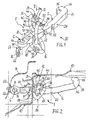
- eine Perspektivansicht eines erfindungsgemäßen Türhalters in einer ersten Ausführungsform im noch nicht im Fahrzeug montierten Zustand,
- Fig. 2
- eine Draufsicht in Pfeilrichtung II gemäß Fig. 1 zur Erläuterung einer bevorzugten Einbausituation im Fahrzeug (hier in der geschlossenen Türstellung),
- Fig. 3
- eine Vorderansicht des Türhalters in Pfeilrichtung III gemäß Fig. 1,
- Fig. 4
- eine Draufsicht in Pfeilrichtung IV gemäß Fig. 3,
- Fig. 5 bis 7
- weitere Ansichten wie in Fig. 2 in verschiedenen Öffnungsstellungen der Fahrzeugtür zur Veranschaulichung der Kinematik,
- Fig. 8
- eine Vorderansicht analog zu Fig. 3, jedoch in der Stellung gemäß Fg. 7 (siehe dort Pfeilrichtung VIII),
- Fig. 9
- einen Schnitt in der Ebene A-A gemäß Fig. 8,
- Fig. 10
- eine Schnittansicht wie in Fig. 9, jedoch in einem noch nicht im Fahrzeug montierten Anlieferzustand,
- Fig. 11 bis 28
- zahlreiche Ausführungsvarianten eines erfindungsgemäßen Halteteils jeweils mit einer Perspektivansicht und einer zugehörigen Vorder-bzw. Rückansicht.
- Fig. 1
- a perspective view of a door holder according to the invention in a first embodiment in the not yet mounted in the vehicle state,
- Fig. 2
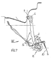
- a plan view in the direction of arrow II of Figure 1 to explain a preferred installation situation in the vehicle (here in the closed position),
- Fig. 3
- a front view of the door holder in the direction of arrow III of FIG. 1,
- Fig. 4
- a top view in the direction of arrow IV of FIG. 3,
- Fig. 5 to 7
- further views as in FIG. 2 in different open positions of the vehicle door to illustrate the kinematics,
- Fig. 8
- a front view analogous to FIG. 3, but in the position according to FIG. 7 (see arrow VIII there),
- Fig. 9
- a section in the plane AA of FIG. 8,
- Fig. 10
- 4 a sectional view as in FIG. 9, but in a delivery state not yet mounted in the vehicle,
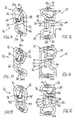
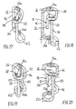
- 11 to 28
- numerous variants of a holding part according to the invention each with a perspective view and an associated front or. Rear View.
In den verschiedenen Figuren der Zeichnung sind gleiche Teile stets mit denselben Bezugszeichen versehen. Daher gilt jede Beschreibung eines Teils unter Bezugnahme auf eine bestimmte Zeichnungsfigur auch bzgl. aller anderen Figuren, in denen das Teil mit dem entsprechenden Bezugszeichen ebenfalls zu erkennen ist.In the various figures of the drawing, like parts are always provided with the same reference numerals. Therefore, any description of a part with reference to a particular drawing figure also applies to all other figures in which the part with the corresponding reference numeral is also recognizable.
Ein erfindungsgemäßer Türhalter 1 besteht einerseits aus einem starren, stangen- bzw. streifenförmigen Tür-Fangband 2 sowie andererseits aus einem Halteteil 12. Vorzugsweise ist das Fangband 2 einendig an einem nur zum Teil angedeuteten Fahrzeugholm 4 gelenkig über eine Schwenklagerung 6, d. h. um eine Schwenkachse 8 schwenkbeweglich, befestigbar, während das Halteteil 12 im Bereich eines sogenannten Türkopfes einer ebenfalls nur angedeuteten Fahrzeugtür 10 derart zu befestigen ist, dass es relativ zur Tür 10 ortsfest (starr) angeordnet ist. Das Fangband 2 erstreckt sich relativbeweglich durch das Halteteil 12 hindurch und mit seinem freien, der Schwenklagerung 6 gegenüberliegenden Ende 14 mit bewegungsbedingt variabler Länge über das Halteteil 12 hinaus in einen Hohlraum der Tür 10 hinein. Die Tür 10 - und mittelbar auch das Halteteil 12 - ist dabei um eine nicht dargestellte, zur Schwenkachse 8 der Schwenklagerung 6 parallele Schwenkachse schwenkbeweglich geführt, wobei die Tür-Schwenkachse gegenüber der Schwenkachse 8 des Fangbandes 2 derart versetzt angeordnet ist, dass beim Öffnen der Tür 10 praktisch das Fangband 2 relativ zu dem türseitig befestigten Halteteil 12 aus der Tür herausgezogen und beim Schließen hineingeschoben wird. Diese Kinematik lässt sich an Hand der Figuren 2 und 5 bis 7 gut erkennen. Bei dieser Relativbewegung wirkt das Fangband 2 mit dem Halteteil 12 über eine Rasteinrichtung 16 zusammen, wodurch bestimmte Schwenkstellungen (Vorzugsstellungen) der Fahrzeugtür 10 definiert werden. Dazu weist das Halteteil 12 mindestens ein Rastelement 18 auf, welches von einem Kraftspeicher 20 in Richtung zum Fangband 2 hin mit einer Federkraft F beaufschlagt ist und mit Raststellen 22 des Fangbandes 2 zusammenwirkt. Für die türseitige Befestigung weist das Halteteil 12 zudem einen Halteabschnitt 24 auf.An inventive door holder 1 consists on the one hand of a rigid, rod-shaped or strip-shaped door-
Erfindungsgemäß besteht das Halteteil 12 mit allen seinen funktionswesentlichen Bestandteilen, dem Halteabschnitt 24, dem mindestens einen Rastelement 18 und dem mindestens einen Kraftspeicher 20, aus einem einstückigen Formteil 26. In den dargestellten, bevorzugten Ausführungsformen ist das Halteteil 12 als Biegeformteil 26 aus einem gebogenen, im Querschnitt insbesondere kreisförmigen und vorzugsweise im Bereich des Halteabschnittes 24 durch Prägen bzw. Stauchen flach umgeformten Federstahldraht ausgebildet.According to the invention, the holding
In der ersten, detailliert in den Fig. 1 bis 10 veranschaulichten Ausführungsform sowie auch in den Ausführungsvarianten gemäß Fig. 11 bis 20 weist das Halteteil 12 nur ein einzelnes, mit an nur einem Längsrand 28 des Fangbandes 2 als Vertiefungen bzw. Ausnehmungen gebildeten Raststellen 22 zusammenwirkendes Rastelement 18 auf. Dabei weist das Halteteil 12 aber zusätzlich ein gegenüberliegendes Widerlagerelement 30 auf (siehe insbesondere Fig. 8 bis 10), welches das Fangband 2 gegen die von dem Kraftspeicher 20 erzeugte Rastfederkraft F abstützt. Wie sich aus Fig. 9 und 10 ergibt, ist hierbei das Widerlagerelement 30 in Längsrichtung des Fangbandes 2 etwas in Richtung dessen freien Endes 14 gegenüber dem Rastelement 18 versetzt angeordnet.In the first embodiment illustrated in detail in FIGS. 1 to 10 as well as in the embodiment variants according to FIGS. 11 to 20, the holding
Das Rastelement 18 wird von einem freien, länglich zylindrischen Draht-Endabschnitt 32 des Biegeformteils 26 gebildet und wirkt deshalb als Gleitelement. Hierbei geht der das Rastelement 18 bildende Endabschnitt 32 über einen den Kraftspeicher 20 bildenden Federabschnitt 34 in den Halteabschnitt 24 über. Der Federabschnitt 34 ist als längliche Torsionsfeder (Drehstabfeder) ausgebildet und hierbei auf der dem Rastelement 18 gegenüberliegenden Seite des Fangbandes 2 angeordnet. Der das Rastelement 18 bildende Endabschnitt 32 geht über einen hebelartigen Verbindungsabschnitt 36 in den Federabschnitt 34 über. Die jeweils benachbarten Abschnitte 32 und 36 sowie 36 und 34 sind jeweils über Biegungen etwa rechtwinklig zueinander angeordnet, so dass sich durch alle drei Abschnitte 32, 34, 36 insgesamt eine (umgekehrt) U-förmige Ausgestaltung ergibt. Der Federabschnitt 34 verläuft somit im Wesentlichen parallel zu dem das Rastelement 18 bildenden Endabschnitt 32 des Formteils 26, wobei der Verbindungsabschnitt 36 das Fangband 2 überquert. Das erwähnte Widerlagerelement 30 wird hierbei von einem am Fangband 2 anliegenden Teilabschnitt des Federabschnittes 34 gebildet.The locking
In einer besonders vorteilhaften Ausgestaltung der Erfindung ist der als Torsionsfeder wirkende Federabschnitt 34 in seinem dem hebelartigen Verbindungsabschnitt 36 naheliegenden (oberen) Bereich in einem Gegenlager 38 gegen quer zu seiner Längserstreckung gerichtete Auslenkbewegungen geführt. Hierbei ist es zudem vorteilhaft, wenn das Gegenlager 38 von dem anderen, dem das Rastelement 18 bildenden Endabschnitt 32 gegenüberliegenden Endabschnitt 40 des Draht-Biegeformteils 26 gebildet ist, indem dieser Endabschnitt 40 derart ösenartig gebogen ist, dass er den Federabschnitt 34 in seinem abzustützenden Bereich umschlingt. Vorzugsweise erfolgt dies mittelbar unter Zwischenanordnung eines ringförmigen Lagerteils 42, welches zweckmäßig aus einem geeigneten Kunststoff besteht.In a particularly advantageous embodiment of the invention acting as a
Der Halteabschnitt 24 ist aus zwei Teilabschnitten des Draht-Formteils 26 gebildet, und zwar aus zwei flach geprägten bzw. gestauchten Abschnitten 24a und 24b. Diese Abschnitte weisen jeweils ein Gewindeelement 44 für die türseitige Befestigung auf. In den dargestellten Ausführungen ist jedes Gewindeelement 44 als Gewindebohrung ausgeführt, es kann sich aber alternativ auch um einen angesetzten Gewindebolzen handeln. Die beiden Teilabschnitte 24a, 24b sind miteinander über einen Zwischenabschnitt 46 des Formteils 26 verbunden. Weiterhin gehen in den dargestellten Ausführungen einerseits der eine (obere) Teilabschnitt 24a in das Gegenlager 38 und der andere (untere) Teilabschnitt 24b in den Federabschnitt 34 über. Wie sich aus den Fig. 2 und 5 bis 7 ergibt, erfolgt die Befestigung des Halteteils 12 im Türkopfbereich in der Fahrzeugtür 10 durch Montageschrauben 48, die durch Löcher im Türblech hindurch in die Gewindebohrungen 44 eingreifen.The holding
Der die Teilabschnitte 24a, 24b des Halteabschnittes 24 direkt miteinander verbindende Zwischenabschnitt 46 kann im Bereich zwischen zwei Umbiegungen von etwa 90 ° geradlinig verlaufen (siehe hierzu die Ausführungen gemäß Fig. 11 bis 14, Fig. 17 und 18 sowie auch Fig. 21 bis 26). In den Ausführungen gemäß Fig. 1 bis 10 und Fig. 15 und 16 sowie 19 und 20 ist jedoch vorgesehen, dass der Zwischenabschnitt 46 einen sickenartig in Richtung zum Fangband 2 hin gebogenen Bereich 50 aufweist.The
Wie sich aus Fig. 10 ergibt, ist in einem noch nicht im Fahrzeug montierten Anlieferzustand des Türhalters 1 das Fangband 2 durch eine Dreipunkt-Anlage in dem Halteteil 12 fixiert gehalten, und zwar durch Anlage an dem Rastelement 18, an dem Widerlagerelement 30 sowie an einem weiteren Anlageabschnitt 52. Hierbei wird der Anlageabschnitt 52 vorzugsweise von dem die Teilabschnitte 24a, 24b des Halteabschnitts 24 verbindenden Zwischenabschnitt 46, vorzugsweise von dessen sickenartigem Bereich 50, gebildet. Gemäß Fig. 9 und 10 wird durch den oben bereits erwähnten Längsversatz zwischen dem Rastelement 18 und dem Widerlagerelement 30 das Fangband 2 durch die Federkraft F mit einem Kippmoment M beaufschlagt und dadurch gegen den Anlageabschnitt 52 bewegt. Wird dann der Türhalter 1 im Fahrzeug montiert, so wird zunächst das Halteteil 12 im Türkopfbereich befestigt, und das Fangband 2 wird mit seinem der Schwenklagerung 6 zugeordneten Ende gegen das Kippmoment M in die Stellung gemäß Fig. 9 bewegt, in der dann die Befestigung über die Schwenklagerung 6 am Fahrzeugholm 4 erfolgt. Das Fangband 2 kommt dann von dem Anlageabschnitt 52 frei, so dass es nur noch zwischen Rastelement 18 und Widerlagerelement 30 anliegt.As is apparent from Fig. 10, in a not yet mounted in the vehicle delivery condition of the door holder 1, the
An seinem freien, der Schwenklagerung 6 gegenüberliegenden Ende 14 weist das Fangband 2 ein Endanschlagelement 54 auf. Vorzugsweise ist dieses Endanschlagelement 54 als einstückige hakenartige Ausformung des Fangbandes 2 gebildet, die mit einer Hakenöffnung 56 (Fig. 2) in der - der ganz geöffneten Türstellung entsprechenden - Endanschlagstellung (Fig. 8 bis 10) das Drahtmaterial des Halteteils 12 insbesondere im Bereich des Widerlagerelementes 30 umgreift.At its free, the pivot bearing 6
Wie sich aus den Darstellungen der Einbausituation in den Fig. 2 und 5 bis 7 ergibt, ist vorteilhafterweise das Rastelement 18 relativ zu dem Halteabschnitt 24 (bzw. relativ zu den Teilabschnitten 24a, 24b) derart angeordnet, dass im montierten, mit der Fahrzeugtür 10 verbundenen Zustand des Halteteils 12 das Rastelement 18 in einem ausserhalb der Fahrzeugtür 10 zwischen dieser und dem Fahrzeugholm 4 liegenden Zwischenraum, also vor dem sogenannten Türkopf, angeordnet ist. Dies wird durch eine entsprechende Biegeformung des Halteteils 12 erreicht. Dieses vorteilhafte Merkmal trägt zu einer sehr kurzen Bauform des Fangbandes 2 bei.As can be seen from the illustrations of the installation situation in FIGS. 2 and 5 to 7, the latching
Was noch die Ausführungsvarianten der Fig. 21 bis 28 betrifft, so weist dabei das Halteteil 12 zwei gegenüberliegende Rastelemente 18 mit entgegengesetzten Wirkrichtungen auf. Die beiden Rastelemente 18 wirken dann mit an gegenüberliegenden Längsrändern des Fangbandes gebildeten Raststellen zusammen (nicht dargestellt). Die beiden Rastelemente 18 sind von zwei freien, zueinander im Wesentlichen parallel verlaufenden Endabschnitten 32 des Formteils 26 gebildet. Jedes Rastelement 18 ist über einen zugehörigen, den Kraftspeicher 20 bildenden Federabschnitt 34 mit dem Halteabschnitt 24 bzw. einem der beiden Teilabschnitte 24a, 24b verbunden. Hierbei wirkt jeder Federabschnitt 34 als längliche Biegefeder und/oder als Torsionsfeder, und zwar je nach Biegeverlaufsform. Dies dürfte an Hand der Darstellungen leicht nachvollziehbar sein.As far as the embodiment variants of FIGS. 21 to 28 are concerned, the holding
Ein weiterer wesentlicher Aspekt der Erfindung, der grundsätzlich auch unabhängig von der bisher beschriebenen erfindungsgemäßen Ausgestaltung angewandt werden kann, betrifft das Fangband 2. Wie sich aus Fig. 9 und 10 ergibt, besteht das Fangband 2 aus einem Metallkern 58 und einer Kunststoffumhüllung 60, wobei erfindungsgemäß der Metallkern 58 derart in Abhängigkeit von der gewünschten Rastkontur vorgeformt ist, dass die Kunststoffumhüllung 60 eine über die gesamte Oberfläche hinweg durchgehend im Wesentlichen konstante Schichtdicke aufweist. Durch diese erfindungsgemäße Ausgestaltung wird - im Vergleich zu einer bekannten Ausführung, bei der eine Rast-Topographie durch bereichsweise Verdickungen des einen durchweg über seine Länge hinweg mit konstantem Querschnitt, z. B. streifenförmig ausgebildeten Metallkern umhüllenden Kunststoffmaterials gebildet wird - erreicht, dass ein sehr einfaches und prozesssicheres Umspritzen des Metallkerns mit dem Kunststoffmaterial möglich ist, wobei sich auch vorteilhaft kurze Zykluszeiten ergeben. Dabei weist das Fangband 2 bevorzugt an jeder Stelle seiner Längserstreckung einen rechteckigen, insbesondere zumindest annähernd quadratischen Querschnitt auf.Another essential aspect of the invention, which in principle can also be used independently of the previously described embodiment according to the invention relates to the
Auf Grund der bisher beschriebenen, bevorzugten Ausgestaltung bestehen somit das Rastelement 18 oberflächig aus Metall und das Fangband 2 im Bereich des die Raststellen 22 aufweisenden Längsrandes 28 oberflächig aus einem Kunststoff, so dass es sich bei den jeweils mit Gleitreibung relativ zueinander bewegenden Teilen um eine Metall-Kunststoff-Paarung handelt. Durch geeignete Materialauswahl können sehr günstige Gleiteigenschaften erreicht werden.Due to the preferred embodiment thus far described, the latching
Alternativ zu der beschriebenen Ausführung können die Materialien auch umgekehrt gewählt werden, d. h. das Rastelement 18 kann oberflächig Kunststoff (z. B. als Ummantelung) aufweisen und auf einer Metallfläche des Fangbandes 2 gleitend geführt sein. Ferner können auch für beide Gleitpartner geeignete Kunststoffe vorgesehen sein.As an alternative to the described embodiment, the materials can also be chosen vice versa, d. H. The latching
Der Vollständigkeit halber sei zu den Ausführungen gemäß Fig. 17 bis 20 noch erwähnt, dass hierbei der (untere) Teilabschnitt 24b des Halteabschnittes 24 derart über eine Ausbiegung 62 von etwa 270 ° in den Federabschnitt übergeht, dass dadurch die Länge des als Torsionsfeder wirkenden Federabschnittes 34 vorteilhaft verlängert wird.For the sake of completeness, it should be mentioned in addition to the embodiments according to FIGS. 17 to 20 that in this case the (lower)
Ein weiterer wesentlicher Aspekt der Erfindung betrifft die Schwenklagerung 6. Auch dieser Aspekt kann grundsätzlich unabhängig von den bisher beschriebenen Erfindungsmerkmalen angewandt werden. Hierbei ist erfindungsgemäß vorgesehen, dass die Schwenklagerung 6 von einem einteilig geformten Lagerteil 64 gebildet ist, welches einseitig einen am Fahrzeugholm 4 zu befestigenden Montageabschnitt 66 und anderseitig einen nietartigen, direkt mit dem Fangband 2 schwenkbeweglich verbundenen und dazu in eine Lageröffnung 68 des Fangbandes 2 eingreifenden Lagerabschnitt 70 aufweist. Gemäß Fig. 3 und 8 sitzt der Lagerabschnitt 70 mit einem zylindrischen Schaft innerhalb der Lageröffnung 68, wobei das Fangband 2 zwischen einem ringstegartigen Lagerrand 72 und einem Nietkopf 74 im Wesentlichen spielfrei und dadurch gegen Kippen geführt ist. Da gemäß Fig. 9 und 10 auch innerhalb der Lageröffnung 68 die Kunststoffumhüllung 60 angeordnet ist, erfolgt die Verbindung des Lagerteils 64 mit dem Fangband 2 vorzugsweise durch sogenanntes Radialnieten, wodurch der Nietkopf 74 nahezu ohne axiale Stauchung des Lagerabschnittes 70 unter hauptsächlich radialer Verformung gebildet wird. Der Lagerabschnitt 70 ist über einen Übergangsabschnitt 75, der beliebig, z. B. etwa S-förmig gebogen sein kann, einstückig mit dem Montageabschnitt 66 verbunden. Der Montageabschnitt 66 kann - wie dargestellt - flach gestaucht sein und ein Montageloch 76 für eine Schraube aufweisen.Another essential aspect of the invention relates to the
Die Erfindung ist nicht auf die dargestellten und beschriebenen Ausführungsbeispiele beschränkt, sondern umfasst auch alle im Sinne der Erfindung gleichwirkenden Ausführungen. So wird insbesondere nochmals betont, dass in Abweichung von der obigen Beschreibung auch eine umgekehrte Anordnung im Fahrzeug möglich ist, indem das Halteteil 12 am Fahrzeugholm 4 befestigt wird, während das Fangband 2 über die Schwenklagerung 6 an der Tür 10 im Türkopfbereich angelenkt wird. Ferner ist die Erfindung bislang auch noch nicht auf die im Anspruch 1 definierte Merkmalskombination beschränkt, sondern kann auch durch jede beliebige andere Kombination von bestimmten Merkmalen aller insgesamt offenbarten Einzelmerkmalen definiert sein. Dies bedeutet, dass grundsätzlich praktisch jedes Einzelmerkmal des Anspruchs 1 weggelassen bzw. durch mindestens ein an anderer Stelle der Anmeldung offenbartes Einzelmerkmal ersetzt werden kann. Insofern ist der Anspruch 1 lediglich als ein erster Formulierungsversuch für eine Erfindung zu verstehen.The invention is not limited to the illustrated and described embodiments, but also includes all the same in the context of the invention embodiments. Thus, it is particularly emphasized again that, in deviation from the above description, a reverse arrangement in the vehicle is possible by the holding
Claims (20)
- Door check (1) for vehicle doors, having a rigid door check strap (2), which is to be fastened at one end in an articulated manner via a pivot bearing (6) to a vehicle pillar (4) or a door, and a holding part (12), which is to be fastened to the door or the vehicle pillar (4), the check strap (2) being guided, so as to be capable of relative movement in its longitudinal direction, through the holding part (12) and cooperating with the holding part (12) via a latching device (16) defining specific pivoted positions of the vehicle door (10), the holding part (12) having at least one latching element (18), which is acted upon by an energy storing device (20) and cooperates with latching locations (22) of the check strap (2), and a holding section (24) for fastening it to the door or pillar,
characterised in that the holding part (12) with the holding section (24), the latching element (18) and the energy storing device (20) consists of a one-piece shaped part (26). - Door check according to Claim 1,
characterised in that the shaped part (26) consists of a bent spring steel wire. - Door check according to Claim 1 or 2,
characterised in that the holding part (12) has a single latching element (18), which cooperates with latching locations (22) formed as indentations on only one longitudinal edge (28) of the check strap (2), and an opposite abutment element (30) which supports the check strap (2) against a latching spring force (F) produced by the energy storing device (20). - Door check according to one of Claims 1 to 3,
characterised in that the latching element (18) is formed by a free end section (32) of the shaped part (26) and merges into the holding section (24) via a spring section (34) forming the energy storing device (20). - Door check according to Claim 4,
characterised in that the spring section (34) is designed as an elongated torsion spring and is arranged on the side of the check strap (2) opposite the latching element (18), the free end section (32), which forms the latching element (18), merging into the spring section (34) via a lever-like connecting section (36). - Door check according to Claim 4 or 5,
characterised in that the spring section (34) runs substantially parallel to the end section (32), forming the latching element (18), of the shaped part (26). - Door check according to one of Claims 3 to 6,
characterised in that the abutment element (30) is formed by a partial section of the spring section (34). - Door check according to one of Claims 5 to 7,
characterised in that the spring section (34) acting as a torsion spring is guided, in its region lying close to the lever-like connecting section (36), in a thrust bearing (38) against deflecting movements directed transversely to its longitudinal extent. - Door check according to Claim 8,
characterised in that the thrust bearing (38) is formed by an end section (40) of the shaped part (26), which end section is bent in the manner of an eye and wraps around the spring section (34) - in particular indirectly with interposition of an annular bearing part (42). - Door check according to Claim 8 or 9,
characterised in that the holding section (24) consists of two partial sections (24a, 24b), each having a threaded element (44) for fastening to the door or pillar, the partial sections (24a, 24b) being connected to one another via an intermediate section (46) and also, on the one hand, to the spring section (34) and, on the other hand, to the thrust bearing (38). - Door check according to one of Claims 3 to 10,
characterised in that, in a delivery state when not yet mounted in the vehicle, the check strap (2) is fixedly held in the holding part (12) by three-point support, to be precise by support of the latching element (18), of the abutment element (30) and of a further supporting section (52), which is preferably formed by the intermediate section (46) connecting the partial sections (24a, 24b) of the holding section (24). - Door check according to one of Claims 1 to 11,
characterised in that the check strap (2) has a limit-stop element (54) at its free end opposite the pivot bearing (6). - Door check according to Claim 12,
characterised in that the limit-stop element (54) is formed as a one-piece hook-like shaped portion of the check strap (2). - Door check according to Claim 1 or 2,
characterised in that the holding part (12) has two opposite latching elements (18) which cooperate with latching locations (22) formed on opposite longitudinal edges of the check strap (2). - Door check according to Claim 14,
characterised in that each latching element (18) is connected to the holding section (24) via an associated spring section (34) forming the energy storing device (20). - Door check according to Claim 15,
characterised in that each spring section (34) is designed as an elongated bending spring and/or torsion spring. - Door check according to one of Claims 14 to 16,
characterised in that the latching elements (18) are formed by two free end sections (32), running substantially parallel to one another, of the shaped part (26). - Door check according to one of Claims 1 to 17,
characterised in that the/each latching element (18) is arranged, relative to the holding section (24), in such a way that it is arranged in an intermediate space lying between the vehicle door (10) and the vehicle pillar (4), when the holding part (12) is in the mounted state in a vehicle. - Door check in particular according to one of Claims 1 to 18,
characterised in that the check strap (2) consists of a metal core (58) and a plastic covering (60), the metal core (58) being pre-shaped in such a way that the plastic covering (60) has a substantially constant layer thickness over the entire surface. - Door check in particular according to one of Claims 1 to 19,
characterised in that the pivot bearing (6) is formed by a one-piece bearing part (64), the bearing part (64) having, on one side, a mounting section (66) to be fastened to the vehicle pillar (4) or the door and, on the other side, a rivet-like bearing section (70) which is pivotably connected directly to the check strap (2) and engages in a bearing opening (68) of the check strap (2).
Applications Claiming Priority (2)
| Application Number | Priority Date | Filing Date | Title |
|---|---|---|---|
| DE202004009894U DE202004009894U1 (en) | 2004-06-23 | 2004-06-23 | Door holder for vehicle doors |
| PCT/EP2005/052748 WO2006000536A1 (en) | 2004-06-23 | 2005-06-14 | Door holder for vehicle doors |
Publications (2)
| Publication Number | Publication Date |
|---|---|
| EP1759080A1 EP1759080A1 (en) | 2007-03-07 |
| EP1759080B1 true EP1759080B1 (en) | 2007-08-15 |
Family
ID=35124620
Family Applications (1)
| Application Number | Title | Priority Date | Filing Date |
|---|---|---|---|
| EP05767975A Not-in-force EP1759080B1 (en) | 2004-06-23 | 2005-06-14 | Door holder for vehicle doors |
Country Status (4)
| Country | Link |
|---|---|
| EP (1) | EP1759080B1 (en) |
| AT (1) | ATE370302T1 (en) |
| DE (2) | DE202004009894U1 (en) |
| WO (1) | WO2006000536A1 (en) |
Cited By (1)
| Publication number | Priority date | Publication date | Assignee | Title |
|---|---|---|---|---|
| WO2009124373A1 (en) * | 2008-04-07 | 2009-10-15 | Multimatic Inc. | Automotive door check with energy storage body |
Families Citing this family (5)
| Publication number | Priority date | Publication date | Assignee | Title |
|---|---|---|---|---|
| US20130055529A1 (en) | 2011-09-06 | 2013-03-07 | Rudolf Gruber | Torsion Bar Door Check |
| FR2996499B1 (en) * | 2012-10-05 | 2014-10-31 | Coutier Moulage Gen Ind | DOOR STOP DEVICE FOR STABILIZING AN OPENING OF A MOTOR VEHICLE AND DOOR STOP ASSEMBLY COMPRISING SUCH A DOOR STOP DEVICE |
| DE102013200929A1 (en) * | 2013-01-22 | 2014-07-24 | Siemens Aktiengesellschaft | Switching mechanism for electro-mechanical switching device, has bearing element comprising bearing opening that is designed, such that arranged bending bead is freely movable in predefined position |
| DE102014108023A1 (en) * | 2014-06-06 | 2015-12-17 | Dr. Ing. H.C. F. Porsche Aktiengesellschaft | A door stay |
| DE102017003565A1 (en) | 2017-04-12 | 2017-10-26 | Daimler Ag | Door brake for a vehicle door |
Family Cites Families (4)
| Publication number | Priority date | Publication date | Assignee | Title |
|---|---|---|---|---|
| DE2644570C3 (en) * | 1976-10-02 | 1981-08-13 | Friedr. Fingscheidt Gmbh, 5620 Velbert | Door holder for vehicle doors |
| DE4330828A1 (en) * | 1993-09-11 | 1995-03-16 | Fingscheidt Gmbh Friedr | Door holders for vehicle doors |
| DE29606304U1 (en) * | 1996-04-05 | 1996-06-27 | Fingscheidt Gmbh Friedr | Door holders for vehicle doors |
| US6687953B1 (en) * | 2000-10-13 | 2004-02-10 | Ventra Group Inc. | Torsion spring door check device |
-
2004
- 2004-06-23 DE DE202004009894U patent/DE202004009894U1/en not_active Expired - Lifetime
-
2005
- 2005-06-14 DE DE502005001263T patent/DE502005001263D1/en not_active Expired - Fee Related
- 2005-06-14 EP EP05767975A patent/EP1759080B1/en not_active Not-in-force
- 2005-06-14 AT AT05767975T patent/ATE370302T1/en not_active IP Right Cessation
- 2005-06-14 WO PCT/EP2005/052748 patent/WO2006000536A1/en active IP Right Grant
Cited By (3)
| Publication number | Priority date | Publication date | Assignee | Title |
|---|---|---|---|---|
| WO2009124373A1 (en) * | 2008-04-07 | 2009-10-15 | Multimatic Inc. | Automotive door check with energy storage body |
| JP2011516758A (en) * | 2008-04-07 | 2011-05-26 | マルティマティック インコーポレイティッド | Automotive door check with energy storage |
| US8567012B2 (en) | 2008-04-07 | 2013-10-29 | Multimatic Inc. | Automotive door check with energy storage body |
Also Published As
| Publication number | Publication date |
|---|---|
| EP1759080A1 (en) | 2007-03-07 |
| DE502005001263D1 (en) | 2007-09-27 |
| WO2006000536A1 (en) | 2006-01-05 |
| ATE370302T1 (en) | 2007-09-15 |
| DE202004009894U1 (en) | 2005-11-10 |
Similar Documents
| Publication | Publication Date | Title |
|---|---|---|
| EP3039214B1 (en) | Positioning device | |
| EP1759080B1 (en) | Door holder for vehicle doors | |
| EP2649261B1 (en) | Closing and damping device for displaceable furniture parts | |
| WO2005071192A1 (en) | Clip fixing element for the assembly of fixture devices such as locks, hinge parts and handles in openings in a thin wall | |
| DE2324288A1 (en) | INVISIBLE ARTICULATED SNAP HINGES, ESPECIALLY FOR FURNITURE DOORS | |
| DE19523790C2 (en) | Extendable roll bar | |
| DE202006020236U1 (en) | Device for opening and closing a movable furniture part and furniture part | |
| EP3621483B1 (en) | Retaining device for a front panel of a drawer | |
| WO2007057332A1 (en) | Door-check arm for vehicle doors | |
| DE19936280A1 (en) | Door hinge system | |
| EP1776511A1 (en) | Door arrester for vehicle doors | |
| DE2804243A1 (en) | HINGE | |
| EP3621484B1 (en) | Holding device for a front panel of a drawer | |
| EP3737816B1 (en) | Furniture hinge, furniture panel, and furniture body | |
| EP0785330B1 (en) | Tailgate hinge for motor vehicles | |
| EP3183408B1 (en) | Control element for a fitting arrangement | |
| AT6747U1 (en) | FURNITURE HINGE WITH OPENING MECHANICS, ESPECIALLY FOR FURNITURE DOORS | |
| DE102015116612A1 (en) | Fitting for a sliding door and method for mounting a sliding door | |
| EP1106110B1 (en) | Height adjustable seat armrest, especially for office chains | |
| EP1365092B1 (en) | Sliding bolt fastener for a pivotable cover element in a vehicle | |
| DE3120065A1 (en) | Furniture hinge | |
| EP1400648A2 (en) | System for opening and closing of lids, especially of tailgates of motor vehicles | |
| DE102018102219A1 (en) | Fastening device for a panel of a drawer | |
| DE2710887C2 (en) | hinge | |
| EP0612903A1 (en) | Torsion strip vied as motor vehicle door check |
Legal Events
| Date | Code | Title | Description |
|---|---|---|---|
| PUAI | Public reference made under article 153(3) epc to a published international application that has entered the european phase |
Free format text: ORIGINAL CODE: 0009012 |
|
| 17P | Request for examination filed |
Effective date: 20061204 |
|
| AK | Designated contracting states |
Kind code of ref document: A1 Designated state(s): AT BE BG CH CY CZ DE DK EE ES FI FR GB GR HU IE IS IT LI LT LU MC NL PL PT RO SE SI SK TR |
|
| GRAP | Despatch of communication of intention to grant a patent |
Free format text: ORIGINAL CODE: EPIDOSNIGR1 |
|
| GRAS | Grant fee paid |
Free format text: ORIGINAL CODE: EPIDOSNIGR3 |
|
| GRAA | (expected) grant |
Free format text: ORIGINAL CODE: 0009210 |
|
| AK | Designated contracting states |
Kind code of ref document: B1 Designated state(s): AT BE BG CH CY CZ DE DK EE ES FI FR GB GR HU IE IS IT LI LT LU MC NL PL PT RO SE SI SK TR |
|
| DAX | Request for extension of the european patent (deleted) | ||
| REG | Reference to a national code |
Ref country code: GB Ref legal event code: FG4D Free format text: NOT ENGLISH |
|
| REG | Reference to a national code |
Ref country code: CH Ref legal event code: EP |
|
| REG | Reference to a national code |
Ref country code: IE Ref legal event code: FG4D Free format text: LANGUAGE OF EP DOCUMENT: GERMAN |
|
| REF | Corresponds to: |
Ref document number: 502005001263 Country of ref document: DE Date of ref document: 20070927 Kind code of ref document: P |
|
| PG25 | Lapsed in a contracting state [announced via postgrant information from national office to epo] |
Ref country code: NL Free format text: LAPSE BECAUSE OF FAILURE TO SUBMIT A TRANSLATION OF THE DESCRIPTION OR TO PAY THE FEE WITHIN THE PRESCRIBED TIME-LIMIT Effective date: 20070815 Ref country code: LT Free format text: LAPSE BECAUSE OF FAILURE TO SUBMIT A TRANSLATION OF THE DESCRIPTION OR TO PAY THE FEE WITHIN THE PRESCRIBED TIME-LIMIT Effective date: 20070815 Ref country code: ES Free format text: LAPSE BECAUSE OF FAILURE TO SUBMIT A TRANSLATION OF THE DESCRIPTION OR TO PAY THE FEE WITHIN THE PRESCRIBED TIME-LIMIT Effective date: 20071126 Ref country code: IS Free format text: LAPSE BECAUSE OF FAILURE TO SUBMIT A TRANSLATION OF THE DESCRIPTION OR TO PAY THE FEE WITHIN THE PRESCRIBED TIME-LIMIT Effective date: 20071215 Ref country code: FI Free format text: LAPSE BECAUSE OF FAILURE TO SUBMIT A TRANSLATION OF THE DESCRIPTION OR TO PAY THE FEE WITHIN THE PRESCRIBED TIME-LIMIT Effective date: 20070815 |
|
| NLV1 | Nl: lapsed or annulled due to failure to fulfill the requirements of art. 29p and 29m of the patents act | ||
| PG25 | Lapsed in a contracting state [announced via postgrant information from national office to epo] |
Ref country code: PL Free format text: LAPSE BECAUSE OF FAILURE TO SUBMIT A TRANSLATION OF THE DESCRIPTION OR TO PAY THE FEE WITHIN THE PRESCRIBED TIME-LIMIT Effective date: 20070815 |
|
| GBV | Gb: ep patent (uk) treated as always having been void in accordance with gb section 77(7)/1977 [no translation filed] |
Effective date: 20070815 |
|
| REG | Reference to a national code |
Ref country code: IE Ref legal event code: FD4D |
|
| EN | Fr: translation not filed | ||
| PG25 | Lapsed in a contracting state [announced via postgrant information from national office to epo] |
Ref country code: GR Free format text: LAPSE BECAUSE OF FAILURE TO SUBMIT A TRANSLATION OF THE DESCRIPTION OR TO PAY THE FEE WITHIN THE PRESCRIBED TIME-LIMIT Effective date: 20071116 Ref country code: DK Free format text: LAPSE BECAUSE OF FAILURE TO SUBMIT A TRANSLATION OF THE DESCRIPTION OR TO PAY THE FEE WITHIN THE PRESCRIBED TIME-LIMIT Effective date: 20070815 |
|
| PG25 | Lapsed in a contracting state [announced via postgrant information from national office to epo] |
Ref country code: SK Free format text: LAPSE BECAUSE OF FAILURE TO SUBMIT A TRANSLATION OF THE DESCRIPTION OR TO PAY THE FEE WITHIN THE PRESCRIBED TIME-LIMIT Effective date: 20070815 Ref country code: GB Free format text: LAPSE BECAUSE OF FAILURE TO SUBMIT A TRANSLATION OF THE DESCRIPTION OR TO PAY THE FEE WITHIN THE PRESCRIBED TIME-LIMIT Effective date: 20070815 Ref country code: PT Free format text: LAPSE BECAUSE OF FAILURE TO SUBMIT A TRANSLATION OF THE DESCRIPTION OR TO PAY THE FEE WITHIN THE PRESCRIBED TIME-LIMIT Effective date: 20080115 Ref country code: CZ Free format text: LAPSE BECAUSE OF FAILURE TO SUBMIT A TRANSLATION OF THE DESCRIPTION OR TO PAY THE FEE WITHIN THE PRESCRIBED TIME-LIMIT Effective date: 20070815 Ref country code: IE Free format text: LAPSE BECAUSE OF FAILURE TO SUBMIT A TRANSLATION OF THE DESCRIPTION OR TO PAY THE FEE WITHIN THE PRESCRIBED TIME-LIMIT Effective date: 20070815 |
|
| PLBE | No opposition filed within time limit |
Free format text: ORIGINAL CODE: 0009261 |
|
| STAA | Information on the status of an ep patent application or granted ep patent |
Free format text: STATUS: NO OPPOSITION FILED WITHIN TIME LIMIT |
|
| PG25 | Lapsed in a contracting state [announced via postgrant information from national office to epo] |
Ref country code: SE Free format text: LAPSE BECAUSE OF FAILURE TO SUBMIT A TRANSLATION OF THE DESCRIPTION OR TO PAY THE FEE WITHIN THE PRESCRIBED TIME-LIMIT Effective date: 20071115 Ref country code: RO Free format text: LAPSE BECAUSE OF FAILURE TO SUBMIT A TRANSLATION OF THE DESCRIPTION OR TO PAY THE FEE WITHIN THE PRESCRIBED TIME-LIMIT Effective date: 20070815 |
|
| 26N | No opposition filed |
Effective date: 20080516 |
|
| BERE | Be: lapsed |
Owner name: FRIEDR. FINGSCHEIDT G.M.B.H. Effective date: 20080630 |
|
| PG25 | Lapsed in a contracting state [announced via postgrant information from national office to epo] |
Ref country code: MC Free format text: LAPSE BECAUSE OF NON-PAYMENT OF DUE FEES Effective date: 20080630 |
|
| PG25 | Lapsed in a contracting state [announced via postgrant information from national office to epo] |
Ref country code: BE Free format text: LAPSE BECAUSE OF NON-PAYMENT OF DUE FEES Effective date: 20080630 |
|
| PG25 | Lapsed in a contracting state [announced via postgrant information from national office to epo] |
Ref country code: EE Free format text: LAPSE BECAUSE OF FAILURE TO SUBMIT A TRANSLATION OF THE DESCRIPTION OR TO PAY THE FEE WITHIN THE PRESCRIBED TIME-LIMIT Effective date: 20070815 Ref country code: DE Free format text: LAPSE BECAUSE OF NON-PAYMENT OF DUE FEES Effective date: 20090101 |
|
| PG25 | Lapsed in a contracting state [announced via postgrant information from national office to epo] |
Ref country code: SI Free format text: LAPSE BECAUSE OF FAILURE TO SUBMIT A TRANSLATION OF THE DESCRIPTION OR TO PAY THE FEE WITHIN THE PRESCRIBED TIME-LIMIT Effective date: 20070815 |
|
| PG25 | Lapsed in a contracting state [announced via postgrant information from national office to epo] |
Ref country code: CY Free format text: LAPSE BECAUSE OF FAILURE TO SUBMIT A TRANSLATION OF THE DESCRIPTION OR TO PAY THE FEE WITHIN THE PRESCRIBED TIME-LIMIT Effective date: 20070815 |
|
| PG25 | Lapsed in a contracting state [announced via postgrant information from national office to epo] |
Ref country code: BG Free format text: LAPSE BECAUSE OF FAILURE TO SUBMIT A TRANSLATION OF THE DESCRIPTION OR TO PAY THE FEE WITHIN THE PRESCRIBED TIME-LIMIT Effective date: 20071115 Ref country code: AT Free format text: LAPSE BECAUSE OF NON-PAYMENT OF DUE FEES Effective date: 20080614 |
|
| REG | Reference to a national code |
Ref country code: CH Ref legal event code: PL |
|
| PG25 | Lapsed in a contracting state [announced via postgrant information from national office to epo] |
Ref country code: LI Free format text: LAPSE BECAUSE OF NON-PAYMENT OF DUE FEES Effective date: 20090630 Ref country code: CH Free format text: LAPSE BECAUSE OF NON-PAYMENT OF DUE FEES Effective date: 20090630 |
|
| PG25 | Lapsed in a contracting state [announced via postgrant information from national office to epo] |
Ref country code: LU Free format text: LAPSE BECAUSE OF NON-PAYMENT OF DUE FEES Effective date: 20080614 Ref country code: HU Free format text: LAPSE BECAUSE OF FAILURE TO SUBMIT A TRANSLATION OF THE DESCRIPTION OR TO PAY THE FEE WITHIN THE PRESCRIBED TIME-LIMIT Effective date: 20080216 |
|
| PG25 | Lapsed in a contracting state [announced via postgrant information from national office to epo] |
Ref country code: TR Free format text: LAPSE BECAUSE OF FAILURE TO SUBMIT A TRANSLATION OF THE DESCRIPTION OR TO PAY THE FEE WITHIN THE PRESCRIBED TIME-LIMIT Effective date: 20070815 |
|
| PG25 | Lapsed in a contracting state [announced via postgrant information from national office to epo] |
Ref country code: IT Free format text: LAPSE BECAUSE OF NON-PAYMENT OF DUE FEES Effective date: 20080630 |
|
| PG25 | Lapsed in a contracting state [announced via postgrant information from national office to epo] |
Ref country code: FR Free format text: LAPSE BECAUSE OF FAILURE TO SUBMIT A TRANSLATION OF THE DESCRIPTION OR TO PAY THE FEE WITHIN THE PRESCRIBED TIME-LIMIT Effective date: 20080411 |