EP1755832B1 - Verbesserung an hydraulischen spannpressen - Google Patents
Verbesserung an hydraulischen spannpressen Download PDFInfo
- Publication number
- EP1755832B1 EP1755832B1 EP05749316.5A EP05749316A EP1755832B1 EP 1755832 B1 EP1755832 B1 EP 1755832B1 EP 05749316 A EP05749316 A EP 05749316A EP 1755832 B1 EP1755832 B1 EP 1755832B1
- Authority
- EP
- European Patent Office
- Prior art keywords
- nut
- bolt
- spacer
- puller bar
- tensioning apparatus
- Prior art date
- Legal status (The legal status is an assumption and is not a legal conclusion. Google has not performed a legal analysis and makes no representation as to the accuracy of the status listed.)
- Active
Links
Images


Classifications
-
- B—PERFORMING OPERATIONS; TRANSPORTING
- B23—MACHINE TOOLS; METAL-WORKING NOT OTHERWISE PROVIDED FOR
- B23P—METAL-WORKING NOT OTHERWISE PROVIDED FOR; COMBINED OPERATIONS; UNIVERSAL MACHINE TOOLS
- B23P19/00—Machines for simply fitting together or separating metal parts or objects, or metal and non-metal parts, whether or not involving some deformation; Tools or devices therefor so far as not provided for in other classes
- B23P19/04—Machines for simply fitting together or separating metal parts or objects, or metal and non-metal parts, whether or not involving some deformation; Tools or devices therefor so far as not provided for in other classes for assembling or disassembling parts
- B23P19/06—Screw or nut setting or loosening machines
- B23P19/067—Bolt tensioners
-
- B—PERFORMING OPERATIONS; TRANSPORTING
- B25—HAND TOOLS; PORTABLE POWER-DRIVEN TOOLS; MANIPULATORS
- B25B—TOOLS OR BENCH DEVICES NOT OTHERWISE PROVIDED FOR, FOR FASTENING, CONNECTING, DISENGAGING OR HOLDING
- B25B29/00—Accessories
-
- B—PERFORMING OPERATIONS; TRANSPORTING
- B25—HAND TOOLS; PORTABLE POWER-DRIVEN TOOLS; MANIPULATORS
- B25B—TOOLS OR BENCH DEVICES NOT OTHERWISE PROVIDED FOR, FOR FASTENING, CONNECTING, DISENGAGING OR HOLDING
- B25B29/00—Accessories
- B25B29/02—Bolt tensioners
-
- Y—GENERAL TAGGING OF NEW TECHNOLOGICAL DEVELOPMENTS; GENERAL TAGGING OF CROSS-SECTIONAL TECHNOLOGIES SPANNING OVER SEVERAL SECTIONS OF THE IPC; TECHNICAL SUBJECTS COVERED BY FORMER USPC CROSS-REFERENCE ART COLLECTIONS [XRACs] AND DIGESTS
- Y10—TECHNICAL SUBJECTS COVERED BY FORMER USPC
- Y10T—TECHNICAL SUBJECTS COVERED BY FORMER US CLASSIFICATION
- Y10T29/00—Metal working
- Y10T29/49—Method of mechanical manufacture
- Y10T29/49826—Assembling or joining
- Y10T29/49863—Assembling or joining with prestressing of part
- Y10T29/49874—Prestressing rod, filament or strand
-
- Y—GENERAL TAGGING OF NEW TECHNOLOGICAL DEVELOPMENTS; GENERAL TAGGING OF CROSS-SECTIONAL TECHNOLOGIES SPANNING OVER SEVERAL SECTIONS OF THE IPC; TECHNICAL SUBJECTS COVERED BY FORMER USPC CROSS-REFERENCE ART COLLECTIONS [XRACs] AND DIGESTS
- Y10—TECHNICAL SUBJECTS COVERED BY FORMER USPC
- Y10T—TECHNICAL SUBJECTS COVERED BY FORMER US CLASSIFICATION
- Y10T29/00—Metal working
- Y10T29/49—Method of mechanical manufacture
- Y10T29/49826—Assembling or joining
- Y10T29/49881—Assembling or joining of separate helix [e.g., screw thread]
-
- Y—GENERAL TAGGING OF NEW TECHNOLOGICAL DEVELOPMENTS; GENERAL TAGGING OF CROSS-SECTIONAL TECHNOLOGIES SPANNING OVER SEVERAL SECTIONS OF THE IPC; TECHNICAL SUBJECTS COVERED BY FORMER USPC CROSS-REFERENCE ART COLLECTIONS [XRACs] AND DIGESTS
- Y10—TECHNICAL SUBJECTS COVERED BY FORMER USPC
- Y10T—TECHNICAL SUBJECTS COVERED BY FORMER US CLASSIFICATION
- Y10T29/00—Metal working
- Y10T29/49—Method of mechanical manufacture
- Y10T29/49826—Assembling or joining
- Y10T29/49947—Assembling or joining by applying separate fastener
- Y10T29/49948—Multipart cooperating fastener [e.g., bolt and nut]
Definitions
- THIS INVENTION relates to hydraulic tensioning jacks to tension fasteners; tensioning systems for the fasteners; and structures and accessories for use therewith.
- Tapered threaded couplings are known, and are commonly used in applications such as coupling "pin & box” ends for drill rods.
- the restricted available dimensions and extreme load requirements of high strength bolted joints mean that a coupling made to these dasigns would be incapable of carrying such forces, were they manufactured to fit into such limited spaces.
- WO00/51791 discloses a washer like spacer, which had to be interposed between the tensioned nut and the component to be clamped in order to fill the gap between the nut and the component when the tension jack applies tension to the nut in order to hold the tension, when the tension jack is subsequently released.
- the washer like spacer having two spacer halves each with one plane face and one ramped face. In order to prevent any relative motion of the spacer halves when loaded and when under load, the spacer halves have to be secured against movement.
- the spacer halves are held in position by threaded bolts accommodated by threaded holes provided in the spacer halves.
- Another tension apparatus also having a spacer between the nut and the component to be clamped in order to maintain tension after release of the tension jack is given in DE2356604 .
- the spacer again is built in two part form like a circular washer cut radially into two spacer halves.
- the upper face of the ring supporting the nut is radially sloped.
- the ring is provided with locking pins for enabling adaptation of the lateral distance between the two spacer halves and by that the adaptation of the "thickness" of the spacer.
- the spacer has a sloped flank provided to engage with a protection bushing of the nut in order to prevent radial drifting of the spacer halves under load.
- bolt shall be used throughout the specification to include studbolts, studs and other fasteners used to connect two or more components/articles/items together.
- the present invention resides in a method of tensioning a bolt according to independent claim 1.
- a segmented sleeve is provided on the puller barof the tensioning apparatus and is selectively engageable with the nut to provide a releasable connection between the puller bar and the nut.
- the segments of the sleeve and puller bar have complementary thread profiles to form a high strength Buttress-threaded Tapered Cone (BTC) coupling between the sleeve and the puller bar (hereinafter referred to as a "BTC coupling" throughout the description and claims).
- BTC Buttress-threaded Tapered Cone
- a peripheral ring selectively radially retracts or extends the segments, relative to the puller bar, out of, or into, engagement with the nut.
- the present invention resides in an apparatus according to independent claim 5 for effecting the method of the first aspect.
- the high strength Buttress-threaded Tapered Cone (BTC) coupling As disclosed in International Publication WO 00/51791 , the high strength Buttress-threaded Tapered Cone (BTC) coupling, as used with the embodiments hereinafter described and illustrated, has the added advantage of being very quick to engage.
- a normal parallel threaded coupling has to be rotated through every turn of its engaged length, whereas the buttresses of the BTC coupling will be fully home in some 2-3 turns, depending on the taper angle and pitch.
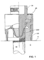
- FIG. 1 is an example of a known hydraulic tensioner in accordance with International Publication WO 00/51791 , where the puller bar 35 of the tensioning apparatus 25 is internally coupled, via a BTC coupling 200, to the bolt 19, fitted with nut 20.
- a bridge 38 extends around the nut 20 and engages the face F of a component C to be clamped by the tensioned bolt 19 (and nut 20).
- the bolt 19 has been fitted with the male portion 201 of the BTC coupling 200.
- the bolt 19 extends above the top of the nut 20.
- the tapered thread may be used to activate the segments in the coupling segments to be hereinafter described, and not just provide a connection between the bolt 19 and the puller bar 35.
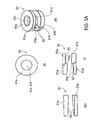
- FIGS. 3A (i) to (iv) and 3B (i) to (iv) show two types of expanding spacers 51,53 which can be placed under the nut to close the strain gap.
- the expanding spacer 51 of FIGS. 3A(i) to (iv) has two complementary spacer halves 51 a, 51 b, each with a substantially circular bore 51 c, 51 d and a planar end face 51 e, 51 f.
- the spacer halves 51 a, 51 b have helically ramped faces 52, terminated by abutment faces 51 g, 51 h.
- the angle of inclination of the ramp faces 52 to the planar end faces 51 e, 51 f will be selected so that there will be no relative rotational motion between the spacer halves 51 a, 51 b when the expanding spacer 51 is interposed between the nut 20 and the component.
- a typical angle is 13°.
- the expanding spacer 53 of FIGS. 3B(i) to (iv) has spacer halves 53a, 53b, which are substantially elliptical in plan view - see FIG. 3B(ii) , with elongate bores 53c, 53d and planar end faces 53e, 53f.
- the spacer halves 53a, 53b have respective ramp faces 54 which are arranged to cause the axial length of the expanding spacer 53 to be increased as the spacer halves 53a, 53b are moved relative to each other in the direction of the arrows A in FIG. 3B(i) .
- the angles of the ramp faces 54 will be selected to prevent relative lateral movement of the spacer halves 53a, 53b as the clamping force is applied by the nut 20 when the tensioner 25 is released.
- the expanding spacer 53 may be fitted with simple mechanisms (not shown), such as an eccentric drive ring, to simplify the simultaneous insertion of the spacer halves 53a, 53b.
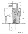
- an expanding spacer 51 is interposed between the face F of the component C and the lower face of nut 120, which extends above the bolt 19, the extension portion 121 of the nut 120 having a parallel thread 121 a complementary to the external thread 35a on the puller bar 35 of the tensioning apparatus 25.
- the nut 120 provides an intermediate coupler between the puller bar 35 and bolt 19, to enable the tensile loads to be transmitted therebetween.
- the expanding spacer 51 is operated, by relative rotation of the two halves 51 a, 51b, to close the "strain gap" between the nut 120 and face F.
- the expandable spacer 51 is replaced by the expandable spacer 53.
- the spacer halves 53a, 53b are moved in the direction of the arrows B to axially expand the spacer 53 and occupy the space between the lower face 122 of the nut 120 and the face F of the component C.
- the angle of the ramp faces 54 on the spacer halves 53a, 53b preclude any lateral movement of the spacer halves 53a, 53b when the tension applied to the nut 120 by the puller bar 35 is released.
- the extension portion 121 of the nut 120 and the puller bar 35 are provided with the quick release BTC coupling 200 of the type hereinbefore described.
- FIGS. 7 and 8 show bolt tensioning assemblies as described above with the addition of a "quick-connect” coupling in semi-automatic and fully automatic configurations. These will be discussed in more detail following.
- Hydraulic Bolt Tensioners are widely accepted as being an accurate and reliable means of applying bolt tension.
- the slowest part of their operation is the mounting and removal of the tool onto the stud. It has been most desirable to produce tools which can avoid having to undertake the lengthy process of winding their connecting pieces on and off.
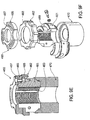
- the puller bar 35 is provided with a segmented sleeve 60, to provide a "quick-release" connection of the nut 120 to the puller bar 35.
- the segmented sleeve 60 has three segments 61, where buttress-threads 202, 201 in the segments 61, and the puller bar 35, provide the BTC coupling 200 between the puller bar 35 and the segments 61, and allow the segments, which have external threads 203, to be moved radially outwardly to engage the threads in the extension 121 on nut 120.
- a locking mechanism 64 extends through the puller bar 35 and has a drive plate 65 at its inner end, with drive pins 66 engaged in grooves in the end faces of the segments 61.
- the grooves are radially "ramped” so that rotation of the drive plate 65 causes the segments 61 to more radially into, or out of, engagement with the internal threads in the extension portion 121 of the extended nut 120.
- the extended portion 121 of the nut 120 and the external faces of the segments have complementary parallel threads, while the puller bar 35 and internal faces of the segments 61 are connected by a BTC coupling 200.
- the locking mechanism is activated by rotating the locking mechamism clockwise, this rotation being transmitted to the drive plate 65 and pins 66, and thence to the segmented sleeve 60.
- the action of the sleeve rotating against the cone thread of the puller bar 35 expands the segments 61 to fully engage the internal threads of the extended nut 120.
- the tensioner is pressurized and the spacer 51, 53 expanded to close the strain gap. Pressure is then released, and the tensioner disengaged by reversing the action of the locking mechanism 64 to retract the sleeve segments.
- FIGS. 8 , 8A and 8B show a tensioner of similar construction wherein the action of expanding the sleeve to engage the internal thread of the extended nut 120 is initiated by rotating the puller bar 135 clockwise.
- the puller bar 135 engages a friction plate 166 on the segments 161. In this embodiment, the puller bar 135 must be free to rotate.
- the segments 61 are spring-loaded to retract from engagement when the puller bar 35 is screwed counter-clockwise.
- the segments 161 of the collar 160 have external threads 162 engageable with the threads 122 in the extension 121 of the nut 120 engaged with bolt 119 to be tensioned.
- the internal threads 163 in the segments 161 are designed to form a BTC coupling with the threads 136 on the puller bar 135 of the hydraulic tensioner 125.
- the segments 161, engaged with the puller bar 135 move radially outwardly into engagement with the extension 121 of nut 120 to enable the nut 120 to apply the tensioning load to the bolt 119.
- FIGS. 9A and 9B show a quick-release tensioner with the above retaining mechanisms.
- the segments 61 and base cup 68 have complementary threads.
- the pitch of the conic thread should ideally be selected to produce movement laterally and axially compatible with the flank angle of the bolt thread. If the pitch was equal, this would occur naturally, but in order to close the sleeve rapidly, it is most desirable to have a large pitch on the conic thread.
- FIGS. 9C and 9D ; and 9E and 9F illustrate respective segmented connectors which employ a taper cup rather than a threaded cup, to be activated by movement of various hand-rotated "components".
- the connector 360 of FIGS. 9C and 9D has a single top cap 362 engaged with the three segments 361 seated in conical cup 368.
- the top cap 362 has pins 369 received in grooves 369a in about the segments 361.
- the top cap 362 is pushed down and rotated to cause the internal threads 363 to engage, eg., a bolt (not shown).
- the rotation of the cap 362 causes the segments 361 to be rotated about, and move down, the bolt and into the cup 368, locking the segments 361 into engagement with the bolt.
- the "double cap” connector 460 of FIGS. 9E and 9F allows the operator to hold one cap and rotate the other to effect engagement.
- the connector 460 is spring-loaded to snap onto the bolt and provides a stand-off position when removed by reverse rotation.
- the connector 460 has an operating ring (or cap) 465 with elongated, curved slots 467 which receive pins (not shown) that pass through radial slots 468 in the cap 462 and are received in holes 469 in the segments 461.
- the slots 467 in the operating ring 465 are radially divergent in plan view so that, as the operating ring 465 is rotated relative to the cap 462, the pins are caused by slots 467 to move the segments 461 radially inwardly (or optionally), and downwardly, into locking engagement (or upwardly for release) in the tapered cup 470, with the internal threads 463 locked to the bolt (not shown).
- FIGS. 10A to 10D demonstrate the relationship between pitch and lateral displacement, assuming a 45° cone angle, generating 1:1 axial Vs lateral movement. The amount of lateral displacement per rotation will be described by the cone angle, which therefore correlates with the selected pitch of the drive thread.
- FIG. 10A shows the maximum lateral displacement required, generated by a 1 ⁇ 2 turn of a cone with a thread pitch of 6mm; while FIG. 10B illustrates the displacement generated by a 1 ⁇ 4 turn of a cone within a 12mm thread pitch. (The angles must be complementary to generate equal lateral displacement during rotation.)
- FIGS. 10C to 10D show the relationship between lateral displacement, thread pitch and flank angle of the driving collar necessary to maintain equal incremental lateral movement.
- a derivable driving flank angle can be calculated trigonometrically from known factors for any particular combination of thread forms.
- This mechanism is also used in the provision of automated "bolt grabber” mechanisms which negate the need to screw tensioners on and off bolts for installation and removal.
- FIG. 11 shows such a tensioner wherein closure of the segmented sleeve is accomplished by turning it clockwise using the drive pin 65. This action closes the mechanism onto the bolt thread as the segments 61 are forced into the cone. Tensile load is then applied hydraulically via the puller 35 with radial thrust forces generated from reaction from the thread's flanks seeking to tighten the grip of the device onto the stud 19. It is possible to add further automation to this type of tensioner by triggering the movement of the segmented sleeves, for example by using a rotational assembly which engages segmented sleeves directly similar to that of FIG. 7 , a puller bar and collar rotating independently of the tensioner body as in FIG.
- FIG. 12 which also illustrates a means by which rotation of the internal components may be achieved hydraulically.
- a hydraulic piston 501 in a cylinder 502 in puller bar 535 is connected to a double-start helix rod 503 which passes through a threaded plate 504.
- the distal end of the helix rod 503 has splines 505 engaged in a drive plate 506 and operable to rotate the segments 561 inwardly, relative to the puller bar 535, via the BTC coupling, the segments 561 engaging the threads 519a about bolt 519.
- a return spring 507 urges the helix rod503 to the segment-released position.
- FIGS. 13A and 13B show a further development of automated tensioners wherein the mechanism for engaging the bolt's thread 619 is initiated by hydraulic input pressure. Fluid introduced through the port 610, initiating movement of the lock piston 621 which then pushes upon the segmented sleeve 661 via the sleeve drive 622. The sleeve segments 661 are forced to engage the threads 619a of the bolt 619 as they are pushed radially inward by reaction from the flank angle of the puller collar 635. As working pressure increases, the retaining hex nut 620 is rotated into position by the hydraulic drive motor 630 acting through the gear train 631 illustrated. Removal of this nut 620 can be achieved by reversing the direction of the motor 630.
- the gear train 631 as illustrated in FIG.13B , has a driving gear 632 (connected to the motor 630), and intermediate gear 633 and a driven gear 634 about nut 620.
- More control over the operation of the tensioner can be achieved by the addition of a sequencing valve 640 internally to allow the action of grabbing onto the thread to be completed before the tensioning force is applied.
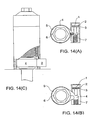
- FIGS. 14A to 14C A further means of rotating this hex nut is shown in FIGS. 14A to 14C . It is important to have components which are radially very slim to fit within the limitations imposed by bridge diameter and hex nuts. This is achieved by using a thin "strap wrench" configuration driven by a hydraulic piston 1, which can provide rapid rotation of the drive socket 5. This arrangement substitutes for the relatively strong gear ring of FIG.13 , and is a lightweight yet robust alternative, with significant cost savings in manufacture.
- the hydraulic piston 1 is received in a cylinder 2 and sealed thereto by an hydraulic seal 3.
- the nose of the piston 1 engages a drive band 4 which has a metal band or strip around a drive socket 5 fitted to a hex nut 6 on the collar.
- a return spring 7 (see FIG. 14B or toggle drive 8 (see FIG. 14A ) is provided in opposition to the piston 1 to allow release of the drive band 4.
- the "stepless wrench” acts in similar fashion to a filter removal strap wrench.
- the band 4 is tightened onto the socket 5 by the mechanical action generated (alternatives shown). The higher the force, the tighter the band 4 will grip in friction.
- the piston 1 reciprocates, drawing the band 4 back and then forcing it forward until it stalls out. At this time, the tensioner will have reached full working pressure, and the nut 6 will therefore be in place.
Claims (5)
- Verfahren zum Spannen eines Bolzens (19, 119), das die folgenden Schritte umfasst:Anbringen einer Schraubenmutter (20, 120) an dem Bolzen (19, 119), wobei sich die Schraubenmutter (20, 120) über den Schaft des Bolzens (19, 119) erstreckt; undVerbinden einer Spannvorrichtung (25, 125) mit der Schraubenmutter (20, 120); so angeordnet, dass die Schraubenmutter (20, 120) die Zugbelastung, die durch die Spannvorrichtung (25, 125) erzeugt worden ist, an den Bolzen (19, 119) überträgt,wobei die Spannvorrichtung (25, 125) eine Zugstange (35, 135, 635) aufweist und die Schraubenmutter (20, 120) einen Verlängerungsabschnitt (121) aufweist, der sich über den Bolzen (19, 119) erstreckt; wobei der Verlängerungsabschnitt (121) der Schraubenmutter (20, 120) ein zylindrisches Innengewinde (121a) aufweist, das zu einem Außengewinde (35a) auf der Zugstange (35) der Spannvorrichtung (25, 125) komplementär ist;wobei ein ausdehnbarer Abstandshalter (51, 53) um den Bolzen (19, 119) zwischen der Schraubenmutter (20, 120) und einer aufzuspannenden Komponente (C) eingefügt ist, wobei der ausdehnbare Abstandshalter (51, 53) axial ausziehbar ist, um die Belastungslücke zwischen der Schraubenmutter (20, 120) und der Komponente (C) aufzunehmen, wenn der Bolzen (19, 119) durch die Zugbelastung gespannt wird, undwobei der ausdehnbare Abstandshalter (51, 53) zwei Abstandshalterhälften (51a, 51b; 53a, 53b) aufweist, wobei jede eine ebene Fläche (51e, 51f; 53e, 53f) und eine geneigte Rampenfläche (52, 54) und eine Bohrung (51c, 51d, 53c, 53d) aufweist, um den Bolzen (19, 119) aufzunehmen, wobei die Abstandshalterhälften (51a, 51b; 53a, 53b) derart relativ gedreht oder seitlich derart bewegt werden, dass die gegenüberliegenden Rampenflächen (52, 54) der Abstandshalterhälften (51a, 51b; 53a, 53b) veranlassen, dass der axiale Abstand zwischen den jeweiligen ebenen Flächen (51e, 51f; 53e, 53f) der Abstandshalterhälften (51a, 51b; 53a, 53b) wahlweise ansteigt oder abnimmt.
- Verfahren nach Anspruch 1, wobei:eine segmentierte Hülse (60, 160, 661) auf der Zugstange (35, 135, 635) der Spannvorrichtung (25, 125) bereitgestellt ist und wahlweise mit der Schraubenmutter (20, 120) in Eingriff gebracht werden kann, um eine lösbare Verbindung zwischen der Zugstange (35, 135, 635) und der Schraubenmutter (20, 120) bereitzustellen.
- Verfahren nach Anspruch 2, wobei:die Segmente (61, 161, 661) der Hülse (60, 160) und der Zugstange (35, 135, 635) komplementäre Gewindeprofile (201, 202, 136, 163) aufweisen, um mittels eines Sägezahn- bzw. Trapezgewindes mit einer kegelförmigen Spitze (Buttress-threaded Tapered Cone (BTC)) eine sehr feste Verbindung (BTC-Verbindung) (200) zwischen der Hülse (60, 160) und der Zugstange (35, 135, 635) zu bilden.
- Verfahren nach Anspruch 3, wobei:ein Umfangsring (465) oder ein anderes Betriebsmittel (65, 66, 166, 362, 369) die Segmente (61, 161, 661) relativ zu der Zugstange (35, 135, 635) wahlweise radial aus dem Eingriff mit der Schraubenmutter (20, 120) heraus zurückzieht oder in den Eingriff mit der Schraubenmutter (20, 120) hinein ausdehnt.
- Vorrichtung, um ein Spannen eines Bolzens (19, 119) zu ermöglichen, wobei die Vorrichtung Folgendes enthält:eine Spannvorrichtung (25, 125), die eine Zugstange (35, 135, 635) aufweist, und eine Schraubenmutter (20, 120), die an den Bolzen (19, 119) angeschraubt werden kann, wobei sich die Schraubenmutter (20, 120) über den Schaft des Bolzens (19, 119) erstreckt; und an die Spannvorrichtung (25, 125) angeschraubt werden kann; so angeordnet, dass die Schraubenmutter (20, 120) die Zugbelastung, die durch die Spannvorrichtung (25, 125) erzeugt worden ist, an den Bolzen (19, 119) überträgt,wobei die Schraubenmutter (20, 120) einen Verlängerungsabschnitt (121) aufweist, der sich über den Bolzen (19, 119) erstreckt; wobei der Verlängerungsabschnitt (121) der Schraubenmutter (20, 120) ein zylindrisches Gewinde (121a) aufweist, das zu einem Außengewinde (35a) auf der Zugstange (35) der Spannvorrichtung (25, 125) komplementär ist; und die Schraubenmutter (20, 120) stellt einen Zwischenverbinder zwischen der Zugstange (35) und dem Bolzen (19, 119) bereit, um Zugbelastungen zu ermöglichen, die dazwischen übertragen werden sollen; undeinen ausdehnbaren Abstandshalter, der um den Bolzen (19, 119) zwischen der Schraubenmutter (20, 120) und einer Komponente (C) eingefügt ist, um aufgespannt zu werden, wobei der spreizbare, sich ausdehnende Abstandshalter (51, 53) axial ausziehbar ist, um die Belastungslücke zwischen der Schraubenmutter (20, 120) und der Komponente (C) aufzunehmen, wenn der Bolzen (19, 119) durch die Zugbelastung gespannt wird,wobei der ausdehnbare Abstandshalter (51, 53) zwei Abstandshalterhälften (51a, 51b; 53a, 53b) aufweist, wobei jede eine ebene Fläche (51e, 51f; 53e, 53f) und eine geneigte Rampenfläche (52, 54) und eine Bohrung (51c, 51d, 53c, 53d) aufweist, um den Bolzen (19, 119) aufzunehmen, wobei die Abstandshalterhälften (51a, 51b; 53a, 53b) derart relativ gedreht oder seitlich derart bewegt werden, dass die gegenüberliegenden Rampenflächen (52, 54) der Abstandshalterhälften (51a, 51b; 53a, 53b) veranlassen, dass der axiale Abstand zwischen den jeweiligen ebenen Flächen (51e, 51f; 53e, 53f) der Abstandshalterhälften (51a, 51b; 53a, 53b) wahlweise ansteigt oder abnimmt.
Applications Claiming Priority (2)
| Application Number | Priority Date | Filing Date | Title |
|---|---|---|---|
| AU2004903276A AU2004903276A0 (en) | 2004-06-17 | Improvements to hydraulic tensioning jacks | |
| PCT/AU2005/000877 WO2005123345A1 (en) | 2004-06-17 | 2005-06-17 | Improvements to hydraulic tensioning jacks |
Publications (3)
| Publication Number | Publication Date |
|---|---|
| EP1755832A1 EP1755832A1 (de) | 2007-02-28 |
| EP1755832A4 EP1755832A4 (de) | 2010-01-13 |
| EP1755832B1 true EP1755832B1 (de) | 2016-01-13 |
Family
ID=35509519
Family Applications (1)
| Application Number | Title | Priority Date | Filing Date |
|---|---|---|---|
| EP05749316.5A Active EP1755832B1 (de) | 2004-06-17 | 2005-06-17 | Verbesserung an hydraulischen spannpressen |
Country Status (6)
| Country | Link |
|---|---|
| US (1) | US8266781B2 (de) |
| EP (1) | EP1755832B1 (de) |
| JP (1) | JP4913731B2 (de) |
| KR (1) | KR101205990B1 (de) |
| CN (1) | CN100546772C (de) |
| WO (1) | WO2005123345A1 (de) |
Families Citing this family (27)
| Publication number | Priority date | Publication date | Assignee | Title |
|---|---|---|---|---|
| DE102004043146B3 (de) * | 2004-09-03 | 2005-11-24 | Hohmann, Jörg | Hydraulische Schraubenspannvorrichtung |
| US7132605B2 (en) * | 2005-04-01 | 2006-11-07 | Adc Telecommunications, Inc. | Split cable seal |
| DE102006047512B4 (de) * | 2006-10-07 | 2014-01-16 | Man Diesel & Turbo Se | Hydraulische Spannvorrichtung |
| AU2007314129B2 (en) * | 2006-10-31 | 2012-09-20 | Technofast Industries Pty Ltd | Fasteners and spacer rings therefor |
| DE102007062615A1 (de) | 2007-12-22 | 2009-07-02 | Hohmann, Jörg | Mutter für Verschraubungen, nämlich segmentierte Mutter |
| CN101592178B (zh) * | 2009-06-30 | 2010-12-08 | 蔡高涛 | 液压加压螺丝 |
| GB2474887B (en) * | 2009-10-30 | 2013-12-04 | Stats Uk Ltd | Device and method for pre-tensioning a coupling |
| DE102010006562B4 (de) * | 2010-02-02 | 2011-11-10 | Jörg Hohmann | Verfahren zum Spannen von Schraubenbolzen, sowie Schraubenbolzen und Schraubenbolzen-Spannvorrichtung zur Durchführung des Verfahrens |
| DE102010016758B4 (de) | 2010-05-03 | 2019-05-02 | Jörg Hohmann | Segmentierte Mutter für Verschraubungen |
| WO2012018396A1 (en) * | 2010-08-04 | 2012-02-09 | Actuant Corporation | Fastener tensioning device and method |
| DE102012105654A1 (de) * | 2012-06-28 | 2014-01-02 | Jörg Hohmann | Spannvorrichtung zum Dehnen eines Gewindebolzens |
| DE102013107096A1 (de) * | 2013-07-05 | 2015-01-08 | Ith Gmbh & Co. Kg | Spannvorrichtung zum Dehnen eines Gewindebolzens |
| US9962818B2 (en) * | 2014-10-17 | 2018-05-08 | The Boeing Company | Apparatus and method for the installation of a thermoformable fastener assembly at a predetermined preload torque value |
| KR101595482B1 (ko) * | 2014-11-07 | 2016-02-18 | 두산중공업 주식회사 | 볼트용 텐셔닝 조립구 |
| US9889529B2 (en) * | 2015-05-01 | 2018-02-13 | Riverhawk Company | System and method for preloading tension in a stud using an anti-seizure spacer for tapered thread connections |
| JP6404804B2 (ja) * | 2015-07-17 | 2018-10-17 | 株式会社シマノ | 自転車用コンポーネント |
| US10036465B2 (en) * | 2015-07-17 | 2018-07-31 | Shimano Inc. | Bicycle component |
| WO2017218870A1 (en) * | 2016-06-16 | 2017-12-21 | Superbolt, Inc. | Improvements to multi-jack tensioners |
| CN108119482B (zh) * | 2017-12-15 | 2019-08-20 | 晋江市青阳明扬汽配制造有限公司 | 一种牢固轮胎螺栓 |
| DE112017008317T5 (de) * | 2017-12-27 | 2020-09-10 | Nabrawind Technologies, S.L | Regelungssystem zum Vorspannen von Bolzen |
| CN108356761A (zh) * | 2018-02-08 | 2018-08-03 | 大连泰凯工业有限公司 | 核电压力容器法兰主螺栓的快速卡接式螺栓拉伸器 |
| AU2019359770A1 (en) * | 2018-10-15 | 2021-06-03 | Nord-Lock Switzerland Gmbh | Hydraulic tensioning and release tool for expansion fasteners |
| US11345005B2 (en) * | 2019-01-11 | 2022-05-31 | William Colburn | Split nut valve seat puller |
| WO2020230082A1 (en) * | 2019-05-16 | 2020-11-19 | Advmet (Pty) Ltd | A mechanical tensioning device and method |
| CN110304572B (zh) * | 2019-07-31 | 2024-01-30 | 嘉兴市金腾机械股份有限公司 | 一种剪式千斤顶 |
| EP3869052A1 (de) * | 2020-02-20 | 2021-08-25 | Siemens Gamesa Renewable Energy Innovation & Technology, S.L. | Vorrichtung und verfahren zur bereitstellung einer sicheren zugverbindung |
| US20230313828A1 (en) * | 2022-03-31 | 2023-10-05 | Mellanox Technologies Ltd. | Mechanical connector |
Citations (2)
| Publication number | Priority date | Publication date | Assignee | Title |
|---|---|---|---|---|
| US3015975A (en) * | 1959-11-17 | 1962-01-09 | Biach Ind | Bolt-tensioning apparatus |
| US3285568A (en) * | 1965-03-17 | 1966-11-15 | Biach Ind | Tensioning apparatus |
Family Cites Families (23)
| Publication number | Priority date | Publication date | Assignee | Title |
|---|---|---|---|---|
| US2736219A (en) * | 1956-02-28 | Bolt tensioner and wrench | ||
| US2571265A (en) * | 1945-06-13 | 1951-10-16 | Leufven Axel Gustav Edvard | Hydraulic tensioning nut |
| US2783024A (en) * | 1953-05-12 | 1957-02-26 | Lee Donovan Henry | Bar gripping means for use in the production of prestressed concrete |
| US2760393A (en) * | 1953-12-14 | 1956-08-28 | Whitehead & Kales Co | Bolt tensioning apparatus |
| CH544236A (de) * | 1970-01-26 | 1973-11-15 | Bieri Hans | Schraubverbindung |
| GB1390012A (en) | 1970-12-21 | 1975-04-09 | Reyrolle Parsons Ltd | Bolt tightening apparatus |
| DE2460961C3 (de) * | 1974-12-21 | 1978-04-13 | Ringfeder Gmbh, 4150 Krefeld | Vorrichtung zum Aufbringen einer Vorspannkraft auf einen Schraubenbolzen mit Mutter |
| JPS5240262A (en) * | 1975-09-27 | 1977-03-29 | Kobe Steel Ltd | Clamping method and device of a bolt |
| GB1507606A (en) * | 1976-03-18 | 1978-04-19 | Doncasters Moorside Ltd | Bolt tightening apparatus |
| US4075923A (en) * | 1976-06-17 | 1978-02-28 | Latham Raymond E | Fastener tensioning apparatus |
| US4433828A (en) | 1981-01-29 | 1984-02-28 | Westinghouse Electric Corp. | Reactor vessel stud closure system |
| JPS5924273A (ja) * | 1982-07-31 | 1984-02-07 | Sharp Corp | 半導体集積回路の特性テスト方式 |
| US4854798A (en) * | 1987-05-29 | 1989-08-08 | Westinghouse Electric Corp. | In-place tensioning washer |
| US5468106A (en) * | 1991-09-02 | 1995-11-21 | Pilgrim Moorside Limited | Hydraulic tensioning device |
| US5253967A (en) * | 1991-11-08 | 1993-10-19 | Biach Industries | Adapter assembly for tensioning threaded fasteners and method of tensioning threaded fasteners |
| GB2274892B (en) * | 1993-02-05 | 1995-08-09 | Hydra Tight Ltd | Spacer washer for bolted joint |
| JPH0825244A (ja) * | 1994-07-21 | 1996-01-30 | Besutoma Kk | ボルト継手における締結力の管理装置 |
| JPH08243945A (ja) * | 1995-03-10 | 1996-09-24 | Unex Corp | 機械的テンショナー |
| AUPP890599A0 (en) | 1999-02-26 | 1999-03-25 | Bucknell, John Wentworth | Tensioning hydraulic nuts |
| US6840726B2 (en) * | 2002-12-16 | 2005-01-11 | Siemens Westinghouse Power Corporation | Tensioning apparatus and method |
| US7066699B2 (en) * | 2002-12-16 | 2006-06-27 | Siemens Westinghouse Power Corporation | Tensioning apparatus and method |
| DE10312412B3 (de) * | 2003-03-20 | 2004-08-05 | Man B&W Diesel A/S | Vorrichtung zum Dehnen eines Zugankers |
| DE102010006562B4 (de) * | 2010-02-02 | 2011-11-10 | Jörg Hohmann | Verfahren zum Spannen von Schraubenbolzen, sowie Schraubenbolzen und Schraubenbolzen-Spannvorrichtung zur Durchführung des Verfahrens |
-
2005
- 2005-06-17 EP EP05749316.5A patent/EP1755832B1/de active Active
- 2005-06-17 KR KR1020077001232A patent/KR101205990B1/ko active IP Right Grant
- 2005-06-17 JP JP2007515742A patent/JP4913731B2/ja active Active
- 2005-06-17 WO PCT/AU2005/000877 patent/WO2005123345A1/en active Application Filing
- 2005-06-17 US US11/570,719 patent/US8266781B2/en active Active
- 2005-06-17 CN CNB2005800200261A patent/CN100546772C/zh active Active
Patent Citations (2)
| Publication number | Priority date | Publication date | Assignee | Title |
|---|---|---|---|---|
| US3015975A (en) * | 1959-11-17 | 1962-01-09 | Biach Ind | Bolt-tensioning apparatus |
| US3285568A (en) * | 1965-03-17 | 1966-11-15 | Biach Ind | Tensioning apparatus |
Also Published As
| Publication number | Publication date |
|---|---|
| JP2008502487A (ja) | 2008-01-31 |
| WO2005123345A1 (en) | 2005-12-29 |
| CN101035651A (zh) | 2007-09-12 |
| US20080301926A1 (en) | 2008-12-11 |
| CN100546772C (zh) | 2009-10-07 |
| US8266781B2 (en) | 2012-09-18 |
| EP1755832A1 (de) | 2007-02-28 |
| JP4913731B2 (ja) | 2012-04-11 |
| EP1755832A4 (de) | 2010-01-13 |
| KR101205990B1 (ko) | 2012-11-29 |
| KR20070026825A (ko) | 2007-03-08 |
Similar Documents
| Publication | Publication Date | Title |
|---|---|---|
| EP1755832B1 (de) | Verbesserung an hydraulischen spannpressen | |
| EP0316417B1 (de) | Befestigungsvorrichtung | |
| US10662989B2 (en) | High-capacity radial fit coupling bolts | |
| CA2862223C (en) | Radially expanding bolt assembly | |
| US7963572B2 (en) | Differential pitch hammerless connection with hydraulic driving mechanism | |
| US5219254A (en) | Expandable fastener and locking means therefor | |
| EP2079561B1 (de) | Befestigungselement und abstandsringe dafür | |
| JP7443384B2 (ja) | 膨張ファスナ用の液圧式の緊張および解放工具 | |
| US5216941A (en) | Tool for securing a fastening device | |
| US20130315665A1 (en) | Mounting device | |
| US4269088A (en) | Wrench tools for castellated nuts | |
| AU2005254122B2 (en) | Improvements to hydraulic tensioning jacks | |
| WO2007003937A1 (en) | Apparatus and method for separating flanges | |
| EP3500758B1 (de) | Vorrichtung zur befestigung und/oder ausrichtung von gegenständen | |
| CN218991646U (zh) | 预应力锚杆的安装装置及锚杆台车的操作臂 | |
| WO2008004039A2 (en) | Limited torque bolt mechanism | |
| WO2015127408A2 (en) | Apparatus for tightening threaded fasteners | |
| EP0124340B1 (de) | Vorrichtung zum axialen Dehnen von Bolzen und Stiften | |
| JPH0673973A (ja) | 管を組み立てるためのねじ溝付き継手を取り付ける装置 | |
| GB2469933A (en) | Ratchet nut and pipe flange closing assembly | |
| CN116745070A (zh) | 改进式螺栓张紧器 |
Legal Events
| Date | Code | Title | Description |
|---|---|---|---|
| PUAI | Public reference made under article 153(3) epc to a published international application that has entered the european phase |
Free format text: ORIGINAL CODE: 0009012 |
|
| AK | Designated contracting states |
Kind code of ref document: A1 Designated state(s): AT BE BG CH CY CZ DE DK EE ES FI FR GB GR HU IE IS IT LI LT LU MC NL PL PT RO SE SI SK TR |
|
| 17P | Request for examination filed |
Effective date: 20061212 |
|
| DAX | Request for extension of the european patent (deleted) | ||
| A4 | Supplementary search report drawn up and despatched |
Effective date: 20091214 |
|
| 17Q | First examination report despatched |
Effective date: 20100331 |
|
| GRAP | Despatch of communication of intention to grant a patent |
Free format text: ORIGINAL CODE: EPIDOSNIGR1 |
|
| INTG | Intention to grant announced |
Effective date: 20150326 |
|
| GRAS | Grant fee paid |
Free format text: ORIGINAL CODE: EPIDOSNIGR3 |
|
| GRAP | Despatch of communication of intention to grant a patent |
Free format text: ORIGINAL CODE: EPIDOSNIGR1 |
|
| INTG | Intention to grant announced |
Effective date: 20150806 |
|
| GRAA | (expected) grant |
Free format text: ORIGINAL CODE: 0009210 |
|
| AK | Designated contracting states |
Kind code of ref document: B1 Designated state(s): AT BE BG CH CY CZ DE DK EE ES FI FR GB GR HU IE IS IT LI LT LU MC NL PL PT RO SE SI SK TR |
|
| REG | Reference to a national code |
Ref country code: GB Ref legal event code: FG4D |
|
| REG | Reference to a national code |
Ref country code: CH Ref legal event code: EP |
|
| REG | Reference to a national code |
Ref country code: IE Ref legal event code: FG4D |
|
| REG | Reference to a national code |
Ref country code: AT Ref legal event code: REF Ref document number: 770190 Country of ref document: AT Kind code of ref document: T Effective date: 20160215 |
|
| REG | Reference to a national code |
Ref country code: DE Ref legal event code: R096 Ref document number: 602005048291 Country of ref document: DE |
|
| REG | Reference to a national code |
Ref country code: LT Ref legal event code: MG4D |
|
| REG | Reference to a national code |
Ref country code: NL Ref legal event code: MP Effective date: 20160113 |
|
| REG | Reference to a national code |
Ref country code: AT Ref legal event code: MK05 Ref document number: 770190 Country of ref document: AT Kind code of ref document: T Effective date: 20160113 |
|
| REG | Reference to a national code |
Ref country code: FR Ref legal event code: PLFP Year of fee payment: 12 |
|
| PG25 | Lapsed in a contracting state [announced via postgrant information from national office to epo] |
Ref country code: NL Free format text: LAPSE BECAUSE OF FAILURE TO SUBMIT A TRANSLATION OF THE DESCRIPTION OR TO PAY THE FEE WITHIN THE PRESCRIBED TIME-LIMIT Effective date: 20160113 |
|
| PG25 | Lapsed in a contracting state [announced via postgrant information from national office to epo] |
Ref country code: GR Free format text: LAPSE BECAUSE OF FAILURE TO SUBMIT A TRANSLATION OF THE DESCRIPTION OR TO PAY THE FEE WITHIN THE PRESCRIBED TIME-LIMIT Effective date: 20160414 Ref country code: ES Free format text: LAPSE BECAUSE OF FAILURE TO SUBMIT A TRANSLATION OF THE DESCRIPTION OR TO PAY THE FEE WITHIN THE PRESCRIBED TIME-LIMIT Effective date: 20160113 Ref country code: FI Free format text: LAPSE BECAUSE OF FAILURE TO SUBMIT A TRANSLATION OF THE DESCRIPTION OR TO PAY THE FEE WITHIN THE PRESCRIBED TIME-LIMIT Effective date: 20160113 |
|
| PG25 | Lapsed in a contracting state [announced via postgrant information from national office to epo] |
Ref country code: AT Free format text: LAPSE BECAUSE OF FAILURE TO SUBMIT A TRANSLATION OF THE DESCRIPTION OR TO PAY THE FEE WITHIN THE PRESCRIBED TIME-LIMIT Effective date: 20160113 Ref country code: PT Free format text: LAPSE BECAUSE OF FAILURE TO SUBMIT A TRANSLATION OF THE DESCRIPTION OR TO PAY THE FEE WITHIN THE PRESCRIBED TIME-LIMIT Effective date: 20160513 Ref country code: IS Free format text: LAPSE BECAUSE OF FAILURE TO SUBMIT A TRANSLATION OF THE DESCRIPTION OR TO PAY THE FEE WITHIN THE PRESCRIBED TIME-LIMIT Effective date: 20160513 Ref country code: SE Free format text: LAPSE BECAUSE OF FAILURE TO SUBMIT A TRANSLATION OF THE DESCRIPTION OR TO PAY THE FEE WITHIN THE PRESCRIBED TIME-LIMIT Effective date: 20160113 Ref country code: PL Free format text: LAPSE BECAUSE OF FAILURE TO SUBMIT A TRANSLATION OF THE DESCRIPTION OR TO PAY THE FEE WITHIN THE PRESCRIBED TIME-LIMIT Effective date: 20160113 Ref country code: LT Free format text: LAPSE BECAUSE OF FAILURE TO SUBMIT A TRANSLATION OF THE DESCRIPTION OR TO PAY THE FEE WITHIN THE PRESCRIBED TIME-LIMIT Effective date: 20160113 |
|
| REG | Reference to a national code |
Ref country code: DE Ref legal event code: R097 Ref document number: 602005048291 Country of ref document: DE |
|
| PG25 | Lapsed in a contracting state [announced via postgrant information from national office to epo] |
Ref country code: DK Free format text: LAPSE BECAUSE OF FAILURE TO SUBMIT A TRANSLATION OF THE DESCRIPTION OR TO PAY THE FEE WITHIN THE PRESCRIBED TIME-LIMIT Effective date: 20160113 Ref country code: EE Free format text: LAPSE BECAUSE OF FAILURE TO SUBMIT A TRANSLATION OF THE DESCRIPTION OR TO PAY THE FEE WITHIN THE PRESCRIBED TIME-LIMIT Effective date: 20160113 |
|
| PLBE | No opposition filed within time limit |
Free format text: ORIGINAL CODE: 0009261 |
|
| STAA | Information on the status of an ep patent application or granted ep patent |
Free format text: STATUS: NO OPPOSITION FILED WITHIN TIME LIMIT |
|
| PG25 | Lapsed in a contracting state [announced via postgrant information from national office to epo] |
Ref country code: CZ Free format text: LAPSE BECAUSE OF FAILURE TO SUBMIT A TRANSLATION OF THE DESCRIPTION OR TO PAY THE FEE WITHIN THE PRESCRIBED TIME-LIMIT Effective date: 20160113 Ref country code: RO Free format text: LAPSE BECAUSE OF FAILURE TO SUBMIT A TRANSLATION OF THE DESCRIPTION OR TO PAY THE FEE WITHIN THE PRESCRIBED TIME-LIMIT Effective date: 20160113 Ref country code: SK Free format text: LAPSE BECAUSE OF FAILURE TO SUBMIT A TRANSLATION OF THE DESCRIPTION OR TO PAY THE FEE WITHIN THE PRESCRIBED TIME-LIMIT Effective date: 20160113 |
|
| 26N | No opposition filed |
Effective date: 20161014 |
|
| PG25 | Lapsed in a contracting state [announced via postgrant information from national office to epo] |
Ref country code: BE Free format text: LAPSE BECAUSE OF FAILURE TO SUBMIT A TRANSLATION OF THE DESCRIPTION OR TO PAY THE FEE WITHIN THE PRESCRIBED TIME-LIMIT Effective date: 20160113 |
|
| PG25 | Lapsed in a contracting state [announced via postgrant information from national office to epo] |
Ref country code: MC Free format text: LAPSE BECAUSE OF FAILURE TO SUBMIT A TRANSLATION OF THE DESCRIPTION OR TO PAY THE FEE WITHIN THE PRESCRIBED TIME-LIMIT Effective date: 20160113 |
|
| REG | Reference to a national code |
Ref country code: CH Ref legal event code: PL |
|
| PG25 | Lapsed in a contracting state [announced via postgrant information from national office to epo] |
Ref country code: BG Free format text: LAPSE BECAUSE OF FAILURE TO SUBMIT A TRANSLATION OF THE DESCRIPTION OR TO PAY THE FEE WITHIN THE PRESCRIBED TIME-LIMIT Effective date: 20160413 Ref country code: SI Free format text: LAPSE BECAUSE OF FAILURE TO SUBMIT A TRANSLATION OF THE DESCRIPTION OR TO PAY THE FEE WITHIN THE PRESCRIBED TIME-LIMIT Effective date: 20160113 |
|
| REG | Reference to a national code |
Ref country code: IE Ref legal event code: MM4A |
|
| PG25 | Lapsed in a contracting state [announced via postgrant information from national office to epo] |
Ref country code: LI Free format text: LAPSE BECAUSE OF NON-PAYMENT OF DUE FEES Effective date: 20160630 Ref country code: CH Free format text: LAPSE BECAUSE OF NON-PAYMENT OF DUE FEES Effective date: 20160630 |
|
| PG25 | Lapsed in a contracting state [announced via postgrant information from national office to epo] |
Ref country code: IE Free format text: LAPSE BECAUSE OF NON-PAYMENT OF DUE FEES Effective date: 20160617 |
|
| REG | Reference to a national code |
Ref country code: FR Ref legal event code: PLFP Year of fee payment: 13 |
|
| PG25 | Lapsed in a contracting state [announced via postgrant information from national office to epo] |
Ref country code: HU Free format text: LAPSE BECAUSE OF FAILURE TO SUBMIT A TRANSLATION OF THE DESCRIPTION OR TO PAY THE FEE WITHIN THE PRESCRIBED TIME-LIMIT; INVALID AB INITIO Effective date: 20050617 Ref country code: CY Free format text: LAPSE BECAUSE OF FAILURE TO SUBMIT A TRANSLATION OF THE DESCRIPTION OR TO PAY THE FEE WITHIN THE PRESCRIBED TIME-LIMIT Effective date: 20160113 |
|
| REG | Reference to a national code |
Ref country code: FR Ref legal event code: PLFP Year of fee payment: 14 |
|
| PG25 | Lapsed in a contracting state [announced via postgrant information from national office to epo] |
Ref country code: LU Free format text: LAPSE BECAUSE OF NON-PAYMENT OF DUE FEES Effective date: 20160617 Ref country code: TR Free format text: LAPSE BECAUSE OF FAILURE TO SUBMIT A TRANSLATION OF THE DESCRIPTION OR TO PAY THE FEE WITHIN THE PRESCRIBED TIME-LIMIT Effective date: 20160113 |
|
| PGFP | Annual fee paid to national office [announced via postgrant information from national office to epo] |
Ref country code: IT Payment date: 20230526 Year of fee payment: 19 Ref country code: FR Payment date: 20230523 Year of fee payment: 19 Ref country code: DE Payment date: 20230516 Year of fee payment: 19 |
|
| PGFP | Annual fee paid to national office [announced via postgrant information from national office to epo] |
Ref country code: GB Payment date: 20230511 Year of fee payment: 19 |