EP1754840B1 - Building element for heat insulation - Google Patents
Building element for heat insulation Download PDFInfo
- Publication number
- EP1754840B1 EP1754840B1 EP06012140A EP06012140A EP1754840B1 EP 1754840 B1 EP1754840 B1 EP 1754840B1 EP 06012140 A EP06012140 A EP 06012140A EP 06012140 A EP06012140 A EP 06012140A EP 1754840 B1 EP1754840 B1 EP 1754840B1
- Authority
- EP
- European Patent Office
- Prior art keywords
- transverse force
- insulating member
- structural
- projection
- concrete
- Prior art date
- Legal status (The legal status is an assumption and is not a legal conclusion. Google has not performed a legal analysis and makes no representation as to the accuracy of the status listed.)
- Active
Links
Images
Classifications
-
- E—FIXED CONSTRUCTIONS
- E04—BUILDING
- E04B—GENERAL BUILDING CONSTRUCTIONS; WALLS, e.g. PARTITIONS; ROOFS; FLOORS; CEILINGS; INSULATION OR OTHER PROTECTION OF BUILDINGS
- E04B1/00—Constructions in general; Structures which are not restricted either to walls, e.g. partitions, or floors or ceilings or roofs
- E04B1/003—Balconies; Decks
- E04B1/0038—Anchoring devices specially adapted therefor with means for preventing cold bridging
Definitions
- the invention relates to a component for thermal insulation between two components, in particular between a building part and a cantilevered outer part, consisting of an insulating body to be arranged between the two components with these traversable and connectable to both components reinforcing elements, being provided as reinforcing elements at least transverse force rods within the Insulating in mutually parallel vertical planes are substantially inclined and bent for connection to the two components at its upper, the supporting member associated history and at its lower, the supported component associated profile such that they are in the said vertical planes at different heights horizontally from Protruding insulating body.
- the present invention has the object to provide a structural element for thermal insulation of the type mentioned above, which is suitable for installation in passive houses, without the static properties suffer hereunder; because the said transverse force rods only reach their optimum properties when they are installed at an angle of about 45 ° - this angle would be made flatter to account for a larger insulator thickness, the transverse force rod would be correspondingly "softer" and could be the static requirements no longer fully meet.
- the component is adapted for installation in passive houses, characterized in that the insulating body on the side facing the supporting member has a recesses for the exit regions of the upper course of the transverse force rods from the insulating free-lying projection in the direction of the supporting member extends into the regions of the horizontally projecting transverse force bar sections so that it completely overlaps the bent transverse force bar sections laterally.
- the projection is formed substantially parallelepiped and adapted to the insulator with the same height and the same longitudinal extent, the release of the protrusion exit regions for the transverse force bars form recesses, which have approximately cylinder segment-like shape with approximately rectangular horizontal cross section in the region of the transverse force rods.
- recesses which have approximately cylinder segment-like shape with approximately rectangular horizontal cross section in the region of the transverse force rods.
- the thickness of the actual insulator plus the thickness of the projection in the order of 20 cm, so this leads to a total of at least almost square vertical cross-section with conventional component and insulator heights in the same order of magnitude.
- in-situ concrete of the adjacent bearing component can be filled into the exit areas of the upper course of the transverse force rods left free from the projection, in which case the insulating body acts as permanent formwork in the usual way; but it is also possible that the recesses is filled with a concrete with other material properties, especially with high-strength or high-performance concrete. This is expediently carried out before the installation of the component, in particular at the component manufacturer.
- high performance concrete which has a better heat-insulating property than the normal reinforced concrete, the partial reduction of the insulator thickness in the recess areas, which could mean a corresponding reduction of the thermal insulation properties, is compensated.
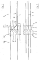
- element 1 for insulation comprises an insulating body 2 with molded projection 3 from demhnem Isolier Sciencesmaterial and a plurality of insulating body traversing reinforcing bars, namely in the upper Isoliersammlung Symposium extending in the horizontal direction tension rods 4 in the lower Isolier Sciences Symposium in the horizontal direction extending pressure bars 5 and transverse force rods 6, wherein the transverse force rods within the Insulating in mutually parallel vertical planes have a substantially inclined course 6b and are bent for connection to two adjacent concrete components at its upper, the supporting member associated course 6a and at its lower, the supported component associated course 6c in such areas 6d, 6e they protrude horizontally from the insulator in the said vertical planes at different heights.
- the projection 3 is arranged on the side facing the supporting member of the insulating body 2 and has recesses 7, which are formed approximately cylinder part segment-like and surrounded an upper outlet portion 6f of the inclined course 6b of the transverse force rods 6 and thus leave free for admission by concrete.
- the projection 3 has the recesses 7 only in the region of the transverse force rods 6, so that the recesses 7 adjacent projection portions 8 through which the tension rods 4 extend laterally overlap the bent transverse force rod portions 6d.
- the recesses 7 provide with the filled concrete for a sufficient support of the transverse force rods 6, whereby the unsupported region of the inclined profile 6b of the transverse force rods 6 is reduced accordingly and approximately the Magnitude corresponds to conventional thermal insulation elements with, for example, only 8cm thick insulating body.
- an order of magnitude of approximately half the length of the inclined course of the transverse force bars of concrete can be surrounded and supported in the area of the recesses, while the other half of the inclined course extends without additional support in the insulating body.
- the present invention has the advantage of providing a structural element for thermal insulation with significantly improved thermal insulation properties with at the same time hardly or hardly reduced static properties available by the transverse force rods are surrounded and supported by the concrete in a substantial part of their inclined course.
Abstract
Description
Die Erfindung betrifft ein Bauelement zur Wärmedämmung zwischen zwei Bauteilen, insbesondere zwischen einem Gebäudeteil und einem vorkragenden Außenteil, bestehend aus einem zwischen den beiden Bauteilen anzuordnenden Isolierkörper mit diesen durchquerenden und an beide Bauteile anschließbaren Bewehrungselementen, wobei als Bewehrungselemente zumindest Querkraftstäbe vorgesehen sind, die innerhalb des Isolierkörpers in zueinander parallelen Vertikalebenen im wesentlichen geneigt verlaufen und zum Anschluss an die beiden Bauteile an ihrem oberen, dem tragenden Bauteil zugeordneten Verlauf und an ihrem unteren, dem getragenen Bauteil zugeordneten Verlauf derart abgebogen sind, dass sie in den genannten Vertikalebenen auf unterschiedlichen Höhen horizontal vom Isolierkörper vorstehen.The invention relates to a component for thermal insulation between two components, in particular between a building part and a cantilevered outer part, consisting of an insulating body to be arranged between the two components with these traversable and connectable to both components reinforcing elements, being provided as reinforcing elements at least transverse force rods within the Insulating in mutually parallel vertical planes are substantially inclined and bent for connection to the two components at its upper, the supporting member associated history and at its lower, the supported component associated profile such that they are in the said vertical planes at different heights horizontally from Protruding insulating body.
Derartige Bauformen von Bauelementen zur Wärmedämmung finden seit langer Zeit Anwendung (siehe auch
Hiervon ausgehend liegt der vorliegenden Erfindung die Aufgabe zugrunde, ein Bauelement zur Wärmedämmung der eingangs genannten Art zur Verfügung zu stellen, das zum Einbau in Passivhäusern geeignet ist, ohne dass hierunter die statischen Eigenschaften leiden; denn die genannten Querkraftstäbe erreichen nur dann ihre optimalen Eigenschaften, wenn sie unter einem Winkel von etwa 45° eingebaut werden - würde dieser Winkel flacher ausgeführt, um einer größeren Isolierkörperdicke Rechnung zu tragen, so würde der Querkraftstab entsprechend "weicher" und könnte die statischen Anforderungen nicht mehr in vollem Umfang erfüllen.Proceeding from this, the present invention has the object to provide a structural element for thermal insulation of the type mentioned above, which is suitable for installation in passive houses, without the static properties suffer hereunder; because the said transverse force rods only reach their optimum properties when they are installed at an angle of about 45 ° - this angle would be made flatter to account for a larger insulator thickness, the transverse force rod would be correspondingly "softer" and could be the static requirements no longer fully meet.
Diese Aufgabe wird erfindungsgemäß dadurch gelöst, dass das Bauelement dadurch für den Einbau bei Passivhäusern angepasst ist, dass der Isolierkörper auf der dem tragenden Bauteil zugewandten Seite einen Aussparungen für die Austrittsbereiche des oberen Verlaufs der Querkraftstäbe aus dem Isolierkörper freilassenden Vorsprung aufweist, der sich in Richtung des tragenden Bauteils bis in die Bereiche der horizontal vorstehenden Querkraftstababschnitte erstreckt, so dass er die abgebogenen Querkraftstababschnitte vollständig seitlich überlappt.This object is achieved in that the component is adapted for installation in passive houses, characterized in that the insulating body on the side facing the supporting member has a recesses for the exit regions of the upper course of the transverse force rods from the insulating free-lying projection in the direction of the supporting member extends into the regions of the horizontally projecting transverse force bar sections so that it completely overlaps the bent transverse force bar sections laterally.
Dadurch ist es erstmals möglich, einen Isolierkörper mit der bei Passivhäusern erforderlichen Dicke von mehr als 15cm und insbesondere von etwa 20 cm zur Verfügung zu stellen, indem an den üblichen Isolierkörper ein Vorsprung angefügt wird, der beispielsweise die noch gegenüber den üblichen 8 cm Isolierkörperdicke fehlende Dicke überbrückt. Dieser Vorsprung hat im Bereich des Austritts der Querkraftstäbe an deren oberen Verlauf jeweils eine Aussparung, die dafür sorgt, dass der abgebogene Verlauf der Querkraftstäbe vom Beton umgeben ist und so die Querkraftstäbe ausreichend statisch unterstützt sind. Hierdurch ist es möglich, die optimale Orientierung des Querkraftstabs von 45° innerhalb des Isolierkörpers beizubehalten, ohne dass die Wärmedämmung einerseits und die statische Funktion des Querkraftstabs andererseits wesentlich beeinträchtigt werden. Auch die statischen Eigenschaften der Zug- und Druckstäbe, die über die Gesamtdicke von mehr als 15 cm vom Isoliermaterial umgeben sind, werden durch die Vergrößerung ihrer nicht vom Beton abgestützten Erstreckung nicht wesentlich verschlechtert.This makes it possible for the first time to provide an insulating body with the passive house required thickness of more than 15cm and in particular of about 20 cm available by a projection is added to the usual insulator, for example, the still lacking compared to the usual 8 cm insulator thickness Thickness bridged. This projection has in the region of the exit of the transverse force rods at their upper course in each case a recess which ensures that the bent course of the transverse force rods is surrounded by the concrete and so the lateral force rods are sufficiently supported statically. This makes it possible to maintain the optimum orientation of the transverse force rod of 45 ° within the insulator, without the thermal insulation on the one hand and the static function of the transverse force rod on the other hand are significantly impaired. Also, the static properties of the tensile and compressive rods exceeding the total thickness of more than 15 cm from the insulating material surrounded by the enlargement of their not supported by the concrete extension not significantly deteriorated.
Zweckmäßigerweise ist der Vorsprung im wesentlichen quaderförmig ausgebildet und an den Isolierkörper angepasst mit gleicher Höhe und gleicher Längserstreckung, wobei die vom Vorsprung freigelassenen Austrittsbereiche für die Querkraftstäbe Aussparungen bilden, die etwa zylinderteilsegmentartige Form aufweisen mit etwa rechteckigem Horizontalquerschnitt im Bereich der Querkraftstäbe. Dadurch ist ein optimaler Anschluss des in die Aussparungen eingefüllten Betons an das angrenzende Betonbauteil gewährleistet und dennoch eine ausreichend stabile Verankerung der Querkraftstäbe im Beton ermöglicht.Conveniently, the projection is formed substantially parallelepiped and adapted to the insulator with the same height and the same longitudinal extent, the release of the protrusion exit regions for the transverse force bars form recesses, which have approximately cylinder segment-like shape with approximately rectangular horizontal cross section in the region of the transverse force rods. As a result, an optimal connection of the filled into the recesses concrete is guaranteed to the adjacent concrete component and still allows a sufficiently stable anchoring of the transverse force bars in the concrete.
Wenn die Gesamtdicke des Isolierkörpers, also die Dicke des eigentlichen Isolierkörpers zuzüglich der Dicke des Vorsprungs, in der Größenordnung von 20 cm liegt, so führt dies bei üblichen Bauteil- und Isolierkörperhöhen in derselben Größenordnung zu einem insgesamt zumindest nahezu quadratischen Vertikalquerschnitt.If the total thickness of the insulating body, so the thickness of the actual insulator plus the thickness of the projection, in the order of 20 cm, so this leads to a total of at least almost square vertical cross-section with conventional component and insulator heights in the same order of magnitude.
In die vom Vorsprung freigelassenen Austrittsbereiche des oberen Verlaufs der Querkraftstäbe, also in die Aussparungen der Isolierkörper kann einerseits Ortbeton des angrenzenden tragenden Bauteils eingefüllt werden, wobei der Isolierkörper in der üblichen Art und Weise als verlorene Schalung fungiert; ebenso ist es aber auch möglich, dass die Aussparungen mit einem Beton mit anderen Materialeigenschaften, insbesondere mit hochfestem bzw. Hochleistungsbeton ausgefüllt wird. Dies erfolgt zweckmäßigerweise vor dem Einbau des Bauelements insbesondere beim Bauelementhersteller. Durch Verwendung von Hochleistungsbeton, der eine gegenüber dem normalen Stahlbeton bessere Wärmedämmeigenschaft besitzt, wird die teilweise Reduzierung der Isolierkörperdicke in den Aussparungsbereichen, die eine entsprechende Reduzierung der Wärmedämmeigenschaften bedeuten könnte, kompensiert.On the one hand, in-situ concrete of the adjacent bearing component can be filled into the exit areas of the upper course of the transverse force rods left free from the projection, in which case the insulating body acts as permanent formwork in the usual way; but it is also possible that the recesses is filled with a concrete with other material properties, especially with high-strength or high-performance concrete. This is expediently carried out before the installation of the component, in particular at the component manufacturer. By using high performance concrete, which has a better heat-insulating property than the normal reinforced concrete, the partial reduction of the insulator thickness in the recess areas, which could mean a corresponding reduction of the thermal insulation properties, is compensated.
Weitere Merkmale und Vorteile der vorliegenden Erfindung ergeben sich aus der nachfolgenden Beschreibung eines Ausführungsbeispiels anhand der Zeichnungen; hierbei zeigen
Figur 1- ein erfindungsgemäßes Bauelement zur Wärmedämmung in Seitenansicht; und
Figur 2- das Bauelement zur Wärmedämmung in Draufsicht.
- FIG. 1
- an inventive device for thermal insulation in side view; and
- FIG. 2
- the device for thermal insulation in plan view.
Das in den
Der Vorsprung 3 ist auf der dem tragenden Bauteil zugewandten Seite des Isolierkörpers 2 angeordnet und weist Aussparungen 7 auf, die etwa zylinderteilsegmentartig ausgebildet sind und einen oberen Austrittsbereich 6f des geneigten Verlaufs 6b der Querkraftstäbe 6 umgeben und somit für eine Beaufschlagung durch Beton freilassen.The
Betrachtet man sich die Draufsicht auf das Bauelement 1 nach
Zusammenfassend bietet die vorliegende Erfindung den Vorteil, ein Bauelement zur Wärmedämmung mit deutlich verbesserten Wärmedämmeigenschaften bei gleichzeitig nicht bzw. kaum reduzierten statischen Eigenschaften zur Verfügung zu stellen, indem die Querkraftstäbe in einem wesentlichen Teil ihres geneigten Verlaufs vom Beton umgeben und abgestützt sind.In summary, the present invention has the advantage of providing a structural element for thermal insulation with significantly improved thermal insulation properties with at the same time hardly or hardly reduced static properties available by the transverse force rods are surrounded and supported by the concrete in a substantial part of their inclined course.
Claims (8)
- Structural element for heat insulation between two structural parts, in particular between a building part and a projecting outer part, comprising an insulating member (2) to be disposed between the two parts with reinforcing elements (4, 5, 6) passing through it and connectable to both structural parts, wherein as reinforcing elements at least transverse force bars (6) are provided which extend substantially in an inclined manner within the insulating member in vertical planes which are parallel to one another and for connection to the two structural parts are bent on their upper extent (6a) associated with the supporting structural part and on their lower extent (6c) associated with the supported structural part in such a way that they project horizontally from the insulating member in the said vertical planes at different levels, wherein the insulating member (2) has on the side facing the supporting structural part a projection (3) which frees openings (7) for the outlet regions (6f) of the upper extent (6a) of the transverse force bars (6) out of the insulating member, characterised in that the structural element (1) is adapted for installation in passive houses due to the fact that the projection (3) extends in the direction of the supporting structural part and into the regions of the horizontally projecting transverse force bar portions (6a), so that it completely laterally overlaps the bent transverse force bar portions (6d).
- Structural element as claimed in Claim 1, characterised in that the projection (3) has a substantially square shape adapted to the insulating member (2) with the same height and the same longitudinal extent.
- Structural element as claimed in at least one of the preceding claims, characterised in that the openings (7) have a shape like a partial cylindrical segment with an approximately rectangular horizontal cross-section in the region of the transverse force bars.
- Structural element as claimed in at least one of the preceding claims, characterised in that the insulating member (2) together with the projection (3) has a thickness (D) which corresponds approximately to the height of the insulating member (2), resulting in an at least approximately square vertical cross-section of the insulating member with the projection parallel to the said vertical planes of the transverse force bars (6).
- Structural element as claimed in at least one of the preceding claims, characterised in that the insulating member (2) together with the projection (3) has an overall thickness (D) of at least 15 cm.
- Structural element as claimed in at least one of the preceding claims, characterised in that the openings (7) are filled with concrete so that the concrete surrounds the bent transverse force bar portions (6d).
- Structural element as claimed in at least Claim 6, characterised in that the concrete is high-performance concrete and/or is filled into the openings (7) before the installation of the structural element (1) on the two structural parts.
- Structural element as claimed in at least Claim 6, characterised in that the openings (7) freed by the projection (3) are filled by the concrete of the adjoining concrete structural part.
Priority Applications (2)
| Application Number | Priority Date | Filing Date | Title |
|---|---|---|---|
| PL06012140T PL1754840T3 (en) | 2005-08-18 | 2006-06-13 | Building element for heat insulation |
| SI200630217T SI1754840T1 (en) | 2005-08-18 | 2006-06-13 | Building element for heat insulation |
Applications Claiming Priority (1)
| Application Number | Priority Date | Filing Date | Title |
|---|---|---|---|
| DE10539025 | 2005-08-18 |
Publications (3)
| Publication Number | Publication Date |
|---|---|
| EP1754840A2 EP1754840A2 (en) | 2007-02-21 |
| EP1754840A3 EP1754840A3 (en) | 2007-05-16 |
| EP1754840B1 true EP1754840B1 (en) | 2008-12-24 |
Family
ID=37260774
Family Applications (1)
| Application Number | Title | Priority Date | Filing Date |
|---|---|---|---|
| EP06012140A Active EP1754840B1 (en) | 2005-08-18 | 2006-06-13 | Building element for heat insulation |
Country Status (6)
| Country | Link |
|---|---|
| EP (1) | EP1754840B1 (en) |
| AT (1) | ATE418655T1 (en) |
| DE (1) | DE502006002417D1 (en) |
| DK (1) | DK1754840T3 (en) |
| PL (1) | PL1754840T3 (en) |
| SI (1) | SI1754840T1 (en) |
Families Citing this family (1)
| Publication number | Priority date | Publication date | Assignee | Title |
|---|---|---|---|---|
| CN111321801B (en) * | 2018-12-14 | 2023-08-01 | 力维拓有限责任公司 | Building and thermally insulating structural element for installation in a separation seam of a building |
Family Cites Families (3)
| Publication number | Priority date | Publication date | Assignee | Title |
|---|---|---|---|---|
| DE4302682A1 (en) * | 1993-02-01 | 1994-08-04 | Schoeck Bauteile Gmbh | Component for thermal insulation |
| DE4341935C1 (en) * | 1993-12-09 | 1995-04-20 | Schoeck Bauteile Gmbh | Structural element for heat insulation |
| DE9417777U1 (en) * | 1994-11-05 | 1995-01-05 | Dausend Hans Werner | Cantilever panel connection element |
-
2006
- 2006-06-13 SI SI200630217T patent/SI1754840T1/en unknown
- 2006-06-13 AT AT06012140T patent/ATE418655T1/en active
- 2006-06-13 EP EP06012140A patent/EP1754840B1/en active Active
- 2006-06-13 DE DE502006002417T patent/DE502006002417D1/en active Active
- 2006-06-13 PL PL06012140T patent/PL1754840T3/en unknown
- 2006-06-13 DK DK06012140T patent/DK1754840T3/en active
Also Published As
| Publication number | Publication date |
|---|---|
| PL1754840T3 (en) | 2009-06-30 |
| DK1754840T3 (en) | 2009-04-14 |
| EP1754840A3 (en) | 2007-05-16 |
| EP1754840A2 (en) | 2007-02-21 |
| ATE418655T1 (en) | 2009-01-15 |
| SI1754840T1 (en) | 2009-06-30 |
| DE502006002417D1 (en) | 2009-02-05 |
Similar Documents
| Publication | Publication Date | Title |
|---|---|---|
| CH676615A5 (en) | ||
| DE102005039025A1 (en) | Component for thermal insulation | |
| EP1612339B1 (en) | Heat insulating building element | |
| EP1832690B1 (en) | Building element for heat insulation | |
| EP2138641A2 (en) | Construction element for heat insulation and insulating material for construction purposes | |
| EP2486196B1 (en) | Method and device for subsequently attaching a protruding outer part to an existing load-bearing building part | |
| DE102011055142B4 (en) | Double wall and transport anchor for a double wall | |
| DE102011122589A1 (en) | Component for thermal insulation | |
| EP2824249B1 (en) | Thermally insulating component | |
| DE4102332A1 (en) | Balcony mounting - has fibre-reinforced plastic absorbing tension load and passing through insulating body | |
| EP0121685A2 (en) | Pressure element in a heat insulating structural member for projecting parts of buildings | |
| EP0834622B1 (en) | Heat insulated connection between external concrete elements, particularly cantilever parts, and building | |
| EP1630315A1 (en) | Construction element for shear and punching reinforcement | |
| DE19543768A1 (en) | Attachment for balcony on building | |
| EP1754840B1 (en) | Building element for heat insulation | |
| DE3328070C2 (en) | ||
| DE19627342B4 (en) | Component for thermal insulation | |
| EP0609690B1 (en) | Construction element for the thermal insulation of buildings | |
| EP0219792B1 (en) | Heat-insulating load-bearing construction element | |
| EP0933482A2 (en) | Prefabricated element for cantilevered balcony slab | |
| EP1229176A2 (en) | Cantilever plate element | |
| CH711343A2 (en) | Prefabricated building part with an insulation element for connecting a concrete cantilever plate to a concrete structure. | |
| EP3569783B1 (en) | Component for thermal insulation | |
| DE102011056967A1 (en) | Plate connecting element | |
| DE10310896A1 (en) | Reinforcement element for concrete construction |
Legal Events
| Date | Code | Title | Description |
|---|---|---|---|
| PUAI | Public reference made under article 153(3) epc to a published international application that has entered the european phase |
Free format text: ORIGINAL CODE: 0009012 |
|
| AK | Designated contracting states |
Kind code of ref document: A2 Designated state(s): AT BE BG CH CY CZ DE DK EE ES FI FR GB GR HU IE IS IT LI LT LU LV MC NL PL PT RO SE SI SK TR |
|
| AX | Request for extension of the european patent |
Extension state: AL BA HR MK YU |
|
| PUAL | Search report despatched |
Free format text: ORIGINAL CODE: 0009013 |
|
| AK | Designated contracting states |
Kind code of ref document: A3 Designated state(s): AT BE BG CH CY CZ DE DK EE ES FI FR GB GR HU IE IS IT LI LT LU LV MC NL PL PT RO SE SI SK TR |
|
| AX | Request for extension of the european patent |
Extension state: AL BA HR MK YU |
|
| 17P | Request for examination filed |
Effective date: 20071005 |
|
| 17Q | First examination report despatched |
Effective date: 20071109 |
|
| AKX | Designation fees paid |
Designated state(s): AT BE BG CH CY CZ DE DK EE ES FI FR GB GR HU IE IS IT LI LT LU LV MC NL PL PT RO SE SI SK TR |
|
| GRAP | Despatch of communication of intention to grant a patent |
Free format text: ORIGINAL CODE: EPIDOSNIGR1 |
|
| GRAS | Grant fee paid |
Free format text: ORIGINAL CODE: EPIDOSNIGR3 |
|
| GRAA | (expected) grant |
Free format text: ORIGINAL CODE: 0009210 |
|
| AK | Designated contracting states |
Kind code of ref document: B1 Designated state(s): AT BE BG CH CY CZ DE DK EE ES FI FR GB GR HU IE IS IT LI LT LU LV MC NL PL PT RO SE SI SK TR |
|
| REG | Reference to a national code |
Ref country code: GB Ref legal event code: FG4D Free format text: NOT ENGLISH |
|
| REG | Reference to a national code |
Ref country code: CH Ref legal event code: EP |
|
| REG | Reference to a national code |
Ref country code: IE Ref legal event code: FG4D Free format text: LANGUAGE OF EP DOCUMENT: GERMAN |
|
| REF | Corresponds to: |
Ref document number: 502006002417 Country of ref document: DE Date of ref document: 20090205 Kind code of ref document: P |
|
| REG | Reference to a national code |
Ref country code: CH Ref legal event code: NV Representative=s name: R. A. EGLI & CO. PATENTANWAELTE |
|
| REG | Reference to a national code |
Ref country code: RO Ref legal event code: EPE |
|
| REG | Reference to a national code |
Ref country code: SE Ref legal event code: TRGR Ref country code: DK Ref legal event code: T3 |
|
| REG | Reference to a national code |
Ref country code: PL Ref legal event code: T3 |
|
| PG25 | Lapsed in a contracting state [announced via postgrant information from national office to epo] |
Ref country code: ES Free format text: LAPSE BECAUSE OF FAILURE TO SUBMIT A TRANSLATION OF THE DESCRIPTION OR TO PAY THE FEE WITHIN THE PRESCRIBED TIME-LIMIT Effective date: 20090404 Ref country code: BG Free format text: LAPSE BECAUSE OF FAILURE TO SUBMIT A TRANSLATION OF THE DESCRIPTION OR TO PAY THE FEE WITHIN THE PRESCRIBED TIME-LIMIT Effective date: 20090324 |
|
| PGFP | Annual fee paid to national office [announced via postgrant information from national office to epo] |
Ref country code: DK Payment date: 20090622 Year of fee payment: 4 Ref country code: EE Payment date: 20090625 Year of fee payment: 4 Ref country code: IE Payment date: 20090618 Year of fee payment: 4 Ref country code: LT Payment date: 20090604 Year of fee payment: 4 Ref country code: RO Payment date: 20090610 Year of fee payment: 4 Ref country code: SI Payment date: 20090603 Year of fee payment: 4 |
|
| PG25 | Lapsed in a contracting state [announced via postgrant information from national office to epo] |
Ref country code: PT Free format text: LAPSE BECAUSE OF FAILURE TO SUBMIT A TRANSLATION OF THE DESCRIPTION OR TO PAY THE FEE WITHIN THE PRESCRIBED TIME-LIMIT Effective date: 20090525 Ref country code: IS Free format text: LAPSE BECAUSE OF FAILURE TO SUBMIT A TRANSLATION OF THE DESCRIPTION OR TO PAY THE FEE WITHIN THE PRESCRIBED TIME-LIMIT Effective date: 20090424 |
|
| PGFP | Annual fee paid to national office [announced via postgrant information from national office to epo] |
Ref country code: CZ Payment date: 20090604 Year of fee payment: 4 Ref country code: FI Payment date: 20090624 Year of fee payment: 4 Ref country code: LU Payment date: 20090625 Year of fee payment: 4 Ref country code: LV Payment date: 20090626 Year of fee payment: 4 Ref country code: SE Payment date: 20090623 Year of fee payment: 4 |
|
| REG | Reference to a national code |
Ref country code: HU Ref legal event code: AG4A Ref document number: E005507 Country of ref document: HU |
|
| PGFP | Annual fee paid to national office [announced via postgrant information from national office to epo] |
Ref country code: BE Payment date: 20090623 Year of fee payment: 4 Ref country code: SK Payment date: 20090610 Year of fee payment: 4 |
|
| PLBE | No opposition filed within time limit |
Free format text: ORIGINAL CODE: 0009261 |
|
| STAA | Information on the status of an ep patent application or granted ep patent |
Free format text: STATUS: NO OPPOSITION FILED WITHIN TIME LIMIT |
|
| PGFP | Annual fee paid to national office [announced via postgrant information from national office to epo] |
Ref country code: HU Payment date: 20090529 Year of fee payment: 4 |
|
| 26N | No opposition filed |
Effective date: 20090925 |
|
| PG25 | Lapsed in a contracting state [announced via postgrant information from national office to epo] |
Ref country code: MC Free format text: LAPSE BECAUSE OF NON-PAYMENT OF DUE FEES Effective date: 20090630 |
|
| PG25 | Lapsed in a contracting state [announced via postgrant information from national office to epo] |
Ref country code: GR Free format text: LAPSE BECAUSE OF FAILURE TO SUBMIT A TRANSLATION OF THE DESCRIPTION OR TO PAY THE FEE WITHIN THE PRESCRIBED TIME-LIMIT Effective date: 20090325 |
|
| BERE | Be: lapsed |
Owner name: SCHOCK BAUTEILE G.M.B.H. Effective date: 20100630 |
|
| LTLA | Lt: lapse of european patent or patent extension |
Effective date: 20100613 |
|
| PG25 | Lapsed in a contracting state [announced via postgrant information from national office to epo] |
Ref country code: LT Free format text: LAPSE BECAUSE OF NON-PAYMENT OF DUE FEES Effective date: 20100613 Ref country code: FI Free format text: LAPSE BECAUSE OF NON-PAYMENT OF DUE FEES Effective date: 20100613 |
|
| REG | Reference to a national code |
Ref country code: DK Ref legal event code: EBP |
|
| EUG | Se: european patent has lapsed | ||
| REG | Reference to a national code |
Ref country code: EE Ref legal event code: MM4A Ref document number: E002986 Country of ref document: EE Effective date: 20100630 |
|
| PG25 | Lapsed in a contracting state [announced via postgrant information from national office to epo] |
Ref country code: CZ Free format text: LAPSE BECAUSE OF NON-PAYMENT OF DUE FEES Effective date: 20100613 |
|
| REG | Reference to a national code |
Ref country code: SI Ref legal event code: KO00 Effective date: 20110125 |
|
| REG | Reference to a national code |
Ref country code: SK Ref legal event code: MM4A Ref document number: E 5170 Country of ref document: SK Effective date: 20100613 |
|
| PG25 | Lapsed in a contracting state [announced via postgrant information from national office to epo] |
Ref country code: LV Free format text: LAPSE BECAUSE OF NON-PAYMENT OF DUE FEES Effective date: 20100613 |
|
| PG25 | Lapsed in a contracting state [announced via postgrant information from national office to epo] |
Ref country code: HU Free format text: LAPSE BECAUSE OF NON-PAYMENT OF DUE FEES Effective date: 20100614 Ref country code: IE Free format text: LAPSE BECAUSE OF NON-PAYMENT OF DUE FEES Effective date: 20100614 |
|
| PG25 | Lapsed in a contracting state [announced via postgrant information from national office to epo] |
Ref country code: SI Free format text: LAPSE BECAUSE OF NON-PAYMENT OF DUE FEES Effective date: 20100614 Ref country code: EE Free format text: LAPSE BECAUSE OF NON-PAYMENT OF DUE FEES Effective date: 20100630 Ref country code: SK Free format text: LAPSE BECAUSE OF NON-PAYMENT OF DUE FEES Effective date: 20100613 |
|
| PG25 | Lapsed in a contracting state [announced via postgrant information from national office to epo] |
Ref country code: BE Free format text: LAPSE BECAUSE OF NON-PAYMENT OF DUE FEES Effective date: 20100630 |
|
| PG25 | Lapsed in a contracting state [announced via postgrant information from national office to epo] |
Ref country code: RO Free format text: LAPSE BECAUSE OF NON-PAYMENT OF DUE FEES Effective date: 20100613 Ref country code: TR Free format text: LAPSE BECAUSE OF FAILURE TO SUBMIT A TRANSLATION OF THE DESCRIPTION OR TO PAY THE FEE WITHIN THE PRESCRIBED TIME-LIMIT Effective date: 20081224 Ref country code: DK Free format text: LAPSE BECAUSE OF NON-PAYMENT OF DUE FEES Effective date: 20100630 |
|
| PG25 | Lapsed in a contracting state [announced via postgrant information from national office to epo] |
Ref country code: CY Free format text: LAPSE BECAUSE OF FAILURE TO SUBMIT A TRANSLATION OF THE DESCRIPTION OR TO PAY THE FEE WITHIN THE PRESCRIBED TIME-LIMIT Effective date: 20081224 |
|
| PG25 | Lapsed in a contracting state [announced via postgrant information from national office to epo] |
Ref country code: LU Free format text: LAPSE BECAUSE OF NON-PAYMENT OF DUE FEES Effective date: 20100613 Ref country code: SE Free format text: LAPSE BECAUSE OF NON-PAYMENT OF DUE FEES Effective date: 20100614 |
|
| PGFP | Annual fee paid to national office [announced via postgrant information from national office to epo] |
Ref country code: GB Payment date: 20130620 Year of fee payment: 8 |
|
| PGFP | Annual fee paid to national office [announced via postgrant information from national office to epo] |
Ref country code: NL Payment date: 20130620 Year of fee payment: 8 Ref country code: PL Payment date: 20130604 Year of fee payment: 8 Ref country code: FR Payment date: 20130703 Year of fee payment: 8 |
|
| PGFP | Annual fee paid to national office [announced via postgrant information from national office to epo] |
Ref country code: IT Payment date: 20130621 Year of fee payment: 8 |
|
| REG | Reference to a national code |
Ref country code: NL Ref legal event code: V1 Effective date: 20150101 |
|
| GBPC | Gb: european patent ceased through non-payment of renewal fee |
Effective date: 20140613 |
|
| REG | Reference to a national code |
Ref country code: FR Ref legal event code: ST Effective date: 20150227 |
|
| PG25 | Lapsed in a contracting state [announced via postgrant information from national office to epo] |
Ref country code: NL Free format text: LAPSE BECAUSE OF NON-PAYMENT OF DUE FEES Effective date: 20150101 |
|
| PG25 | Lapsed in a contracting state [announced via postgrant information from national office to epo] |
Ref country code: IT Free format text: LAPSE BECAUSE OF NON-PAYMENT OF DUE FEES Effective date: 20140613 |
|
| PG25 | Lapsed in a contracting state [announced via postgrant information from national office to epo] |
Ref country code: GB Free format text: LAPSE BECAUSE OF NON-PAYMENT OF DUE FEES Effective date: 20140613 Ref country code: FR Free format text: LAPSE BECAUSE OF NON-PAYMENT OF DUE FEES Effective date: 20140630 |
|
| REG | Reference to a national code |
Ref country code: PL Ref legal event code: LAPE |
|
| PG25 | Lapsed in a contracting state [announced via postgrant information from national office to epo] |
Ref country code: PL Free format text: LAPSE BECAUSE OF NON-PAYMENT OF DUE FEES Effective date: 20140613 |
|
| PGFP | Annual fee paid to national office [announced via postgrant information from national office to epo] |
Ref country code: AT Payment date: 20170620 Year of fee payment: 12 |
|
| REG | Reference to a national code |
Ref country code: AT Ref legal event code: MM01 Ref document number: 418655 Country of ref document: AT Kind code of ref document: T Effective date: 20180613 |
|
| PG25 | Lapsed in a contracting state [announced via postgrant information from national office to epo] |
Ref country code: AT Free format text: LAPSE BECAUSE OF NON-PAYMENT OF DUE FEES Effective date: 20180613 |
|
| P01 | Opt-out of the competence of the unified patent court (upc) registered |
Effective date: 20230513 |
|
| PGFP | Annual fee paid to national office [announced via postgrant information from national office to epo] |
Ref country code: DE Payment date: 20230623 Year of fee payment: 18 |
|
| PGFP | Annual fee paid to national office [announced via postgrant information from national office to epo] |
Ref country code: CH Payment date: 20230702 Year of fee payment: 18 |