EP1754314B1 - Procédé et système permettant de moduler une séquence de chiffres binaires dans un réseau de communication sans fil - Google Patents
Procédé et système permettant de moduler une séquence de chiffres binaires dans un réseau de communication sans fil Download PDFInfo
- Publication number
- EP1754314B1 EP1754314B1 EP05795329A EP05795329A EP1754314B1 EP 1754314 B1 EP1754314 B1 EP 1754314B1 EP 05795329 A EP05795329 A EP 05795329A EP 05795329 A EP05795329 A EP 05795329A EP 1754314 B1 EP1754314 B1 EP 1754314B1
- Authority
- EP
- European Patent Office
- Prior art keywords
- waveform
- bit
- phase
- data
- current bit
- Prior art date
- Legal status (The legal status is an assumption and is not a legal conclusion. Google has not performed a legal analysis and makes no representation as to the accuracy of the status listed.)
- Expired - Lifetime
Links
Images


Classifications
-
- H—ELECTRICITY
- H04—ELECTRIC COMMUNICATION TECHNIQUE
- H04B—TRANSMISSION
- H04B1/00—Details of transmission systems, not covered by a single one of groups H04B3/00 - H04B13/00; Details of transmission systems not characterised by the medium used for transmission
- H04B1/69—Spread spectrum techniques
- H04B1/7163—Spread spectrum techniques using impulse radio
- H04B1/7176—Data mapping, e.g. modulation
-
- H—ELECTRICITY
- H04—ELECTRIC COMMUNICATION TECHNIQUE
- H04L—TRANSMISSION OF DIGITAL INFORMATION, e.g. TELEGRAPHIC COMMUNICATION
- H04L27/00—Modulated-carrier systems
- H04L27/18—Phase-modulated carrier systems, i.e. using phase-shift keying
-
- H—ELECTRICITY
- H04—ELECTRIC COMMUNICATION TECHNIQUE
- H04B—TRANSMISSION
- H04B1/00—Details of transmission systems, not covered by a single one of groups H04B3/00 - H04B13/00; Details of transmission systems not characterised by the medium used for transmission
- H04B1/69—Spread spectrum techniques
- H04B1/7163—Spread spectrum techniques using impulse radio
- H04B1/719—Interference-related aspects
Definitions
- the invention relates generally to communication systems, and more particularly to modulation fonnats used in wireless communication systems.
- UWB ultra-wide bandwidth
- the FCC order also limits the power spectral density and peak emissions power of UWB signals, e.g. less than -43.1 dBm/MHz.
- One modulation method for UWB uses extremely short time pulses to generate signals with bandwidths greater than 500 MHz, e.g., 1/1,000,000,000 of a second of less, which corresponds to a wavelength of about 300 mm.
- Systems that use short pulses are commonly referred to as impulse radio (IR) systems.
- PPM pulse position modulation
- PAM pulse amplitude modulation
- OOK on-off keying
- BPSK bi-phase shift keying
- UWB systems can achieve high data rates, and are resistant to multi-path impairments due to the large processing gains. Additionally, the use of IR based UWB technology allows for the implementation of low cost, low duty cycle, low power transceivers that do not require local oscillators for heterodyning. Because UWB radios are primarily digital circuits, they can easily be integrated in a semiconductor chip. In UWB systems, multiple users can simultaneously share the same spectrum with no interference to one another, and are ideal for high-speed home and business networking devices, as well as sensor networks.
- the IEEE 802.15.4a standard defines a physical-layer for communications with scalable data rates from 1 Kbs to 1 Mbps, "IEEE P802.15.4a WPAN Alternate PHY - PAR," 2003, for low power, low data rate network.
- IR systems are either time-hopped (TH-IR), or transmitted-reference (TR-IR). Both systems use sequences of short duration pulses, p(t).
- TH-IR time-hopped
- TR-IR transmitted-reference
- modulation and demodulation for TH-IR and TR-IR differ significantly, making TH-IR and TR-IR incompatible in the same network.
- TH-IR system are described by M. Win and R. A. Scholtz, "Ultra-Wide Band Width Time-Hopping Spread-Spectrum Impulse Radio for Wireless Multiple-Access Communications, " in IEEE Trans. On Communications, Vol. 48, No. 4 April 2000, pp. 679- 691 .
- N f pulses where N f is a positive integer.
- the time taken to transmit the bit is T s . This is called the symbol duration.
- the time T s is further partitioned into frames T f , and the frames are partitioned into chips T c corresponding typically to a pulse duration.
- Figure 1B shows the relationship the symbol time T s 101, the frame time T f 102, and the chip time t c 103 for pulses 104 for an example prior art TH-IR waveform 110 for a '0' bit, and a waveform 120 for a '1' bit.
- the pulses are spaced pseudo-randomly among the available chips in a frame according to a "time-hopping" code to minimize the effect of multi user interference.
- the modulation can be binary phase shift keying.
- each bit b is represented as either a positive or negative one b ⁇ ⁇ -1,1 ⁇ .
- an optional sequence denoted as h i,j can be applied to each pulse in the transmitted signal so as to shape the spectrum of the transmitted signal and to reduce spectral lines.
- the sequence, h i,j is called a polarity scrambling sequence with values of either +1 or -1. Different amplitudes are possible to give further degrees of freedom in the shaping of the spectrum.
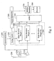
- FIG. 2 shows a conventional coherent TH-IR receiver 200.
- the receiver includes an automatic gain control (AGC) unit 210 coupled to an amplifier 220 that is connected to the receive antenna 230.
- the receiver also includes synchronization 240, timing control 250, channel estimation 260, MMSE equalizer 270, and decoder 280 units.
- Rake receiver fingers 290 input to an adder 295.
- Each rake finger includes a pulse sequence generator, correlator and weight combiner. The rake fingers reduce multipath interference. Due to the density of the multipaths in UWB signals, the number of required RAKE fingers can be large to obtain reasonable performance.
- the output of the adder is equalized and decoded.
- the typical TH-IR receiver has a significant complexity.
- TR-IR systems eliminate the need for a RAKE receiver, R. Hoctor and H. Tomlinson, "Delay-Hopped Transmitted-Reference RF Communications," IEEE Conference on Ultra Wide Band Width Systems and Technologies, 2002, pp. 265-269 .”
- the information is encoded as phase differences of successive pulses in the sequence.
- Each symbol in a TR-IR system is a sequence of time-hopped 'doublets' or pair of two consecutive pulses.
- the first pulse in the pair is referred to as a reference pulse and the second pulse is referred to as a data pulse.
- the two pulses in each pair are separated by a fixed unit of time T d . Multiple pairs can be transmitted for one information bit.
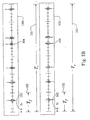
- Figure 3 shows the relationship the symbol time T s 301, the frame time T f 302, and the chip time T c 303 for pulses 304 for an example TH-IR waveform 310 for a '0' bit, and waveform 320 for a '1' bit.
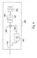
- Figure 4 shows a conventional TR-IR receiver 400, which is significantly simpler than the TH-IR receiver of Figure 2 .
- the receiver includes delay 401, multiplier 402, integrator 403, sampler 407 and decision 404 units.
- the receiver essentially correlates the received signal 405 with a delayed version 406.
- the TR-IR 400 receiver is less complex than the TH-IR receiver 200.
- the reduced complexity is at the cost of requiring twice the number of pulses, and the additional energy required for the reference pulses, nominally 3dB or more.
- WITRISAL K ET AL "Multiuser interference and interframe interference in UWB transmitted reference systems" ULTRA WIDEBAND SYSTEMS, 2004.
- the invention is defined by a method comprising the features of claim 1 and a system comprising the features of claim 13, respectively. Preferred embodiments of this method and of this system are represented in the respective subclaims.
- the invention provides a system and method for incorporating TH-IR and TR-IR transceivers in the same wireless network.
- the invention also provides a modulation fonnat that encodes information bits is such a way to enable both TH-IR and TR-IR receivers to demodulate the same signals.
- the modulation format does not suffer from the inherent 3dB loss when the TH-IR receiver is used.
- the invention can be applied to narrow band, wide band, and ultra-wide band radio systems.
- a method modulates a sequence of bits in a wireless communications network by generating a reference waveform, e.g., a pulse, and a data waveform, e.g., another pulse, of a waveform pair for each current bit.
- the phase of the reference waveform depends on a previously modulated bit, and a difference in phase (polarity) between the reference waveform and the data waveform pair depend on the current bit.
- Our invention provides a system and method that enables both TH-IR and TR-IR transceivers to co-exist in the same wireless network.
- Our idea is based on our observation that TR-IR systems encode an information bit as a phase difference between a reference pulse and a data pulse. Furthermore, the polarity of the reference pulse is inconsequential for the correct operation of the TR-IR system.
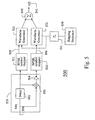
- FIG. 5 show a H-IR transmitter 500 according to the invention.
- the transmitter includes a pre-processor 510 for input bits 501.
- the pre-processor includes a delay 502 and an adder 503.
- the adder sums each input bit 501 to a delayed version of the bit, the sum is inverted 504.
- the pre-processing generates a pair of modulating bits from two successive information bits. It should be noted that more than one pair of modulation bits can be used for each information bit.
- the symbols are modulated 511-512.
- Reference wavefonns, e.g., pulses 505, in the sequence are BPSK modulated 511 according to the input bits 501, and data waveforms, e.g., pulses 506, are BSPK modulated according to the inverted sum.
- Waveform generators 521-522 are applied, according to a hopping sequence 530 and delay T d 531 and the results are combined 540.
- the modulation according to equation (4) shows that a phase difference between the reference pulse and data pulse is identical to a conventional TR-IR system.
- Table A shows the four possible combination of a previous and a current bit, the corresponding values of the reference and data waveforms, and their phase differences or polarities.
- Table A Previous bit Current bit Reference pulse modulation symbol b [2 j / N ⁇ ]-1 Data pulse modulation symbol b ⁇ 2 ⁇ j / N f ⁇ - 1 ⁇ b ⁇ 2 ⁇ j / N f ⁇ ) Phase difference between reference pulse and modulated pulse 0 0 -1 1 180° 0 1 -1 -1 0° 1 0 1 -1 180° 1 1 1 1 0°
- the phase difference between the reference pulse and the data pulse is always 180° regardless of the value of the previous bit. If the current bit is 1, then the phase difference is 0°.
- a TR-IR receiver can demodulate the signal according to the invention.
- the signal can also be demodulated by a TH-IR receiver with improved performance.
- the gain in performance is based on the fact that information is encoded in both the reference pulses and the data pulses.
- the TH-IR receiver can use the energy in the reference pulses to make decisions on the values of the transmitted bits, see Table A.
- a sequence of N f / 2 pairs is transmitted.
- the pair in each frame is described as a sequence of pulses, each with a polarity of the pulses depending on the current and previous bit that are transmitted. There are four possible combinations of pairs.
- the transmitted signal can be described as follows.
- the transmitter transmits a sequence of N f l2 pairs.
- the four possible pairs are given by equation (7).
- the pairs are optionally time hopped and scrambled with a polarity code.
- the invention provides a modulation format with memory. Modulation formats that have memory can be represented by a trellis diagram. Additionally, the transmitted signal is now a two-dimensional signal because two basis signals ⁇ 0 (t) and ⁇ 1 (t) are used to represent the pairs.
- Figure 6 shows a diagram 600 for a Viterbi decoder using a trellis.
- a coherent TH-IR receiver can be used to demodulate the signal.
- Our TH-IR receiver is adapted to accommodate the two-dimensional description of the symbol wavefonn and the memory between consecutive symbols according to the invention.
- FIG. 7 shows the TH-IR receiver 700 according to the invention.
- the RAKE fingers correlate the incoming signal with sequences of the two basis pulses, ⁇ 0 (t) and ⁇ 1 (t).
- the output of each finger is now a 2-D vector 701.
- the outputs of the finger are summed 710 to produce a soft input observations 702 for a conventional maximum likelihood sequence detector (MLSD) 720.
- MLSD maximum likelihood sequence detector
- the MLSD detector determines a most probable path through the trellis 600 for a given sequence of observations 702. Methods that approximate the MSLD detector, such as Viterbi decoding can also be used.
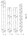
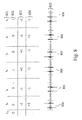
- Figure 8 shows the relationship between symbols, bits and modulated waveforms.
- the six symbols of the sequence 801 to be modulated are labeled b 0 to b 5 , with a previous encoded symbol '0'.
- the symbols in the example sequence are 0 1 1 0 0 1 802 , which correspond to reference bits - 1 , - 1 , + 1 , + 1 , - 1 , - 1 ⁇ 803 , and data bits + 1 , - 1 , + 1 , - 1 , + 1 , - 1 ⁇ 804 , and a waveform 805 with reference and data pulse pairs 806, where a "down" pulse encodes '-1' and an 'up' pulse encodes '+1'.
- the waveform 805 has the properties described earlier. Specifically, the phase difference between the reference pulse and the data pulse in each pair 806 contains the information about the current bit being transmitted. For each pair the phase difference is 180° when a '0' bit is transmitted, and a 0° phase difference when a '1' bit is transmitted.
- the sequence of pairs also contains the information about the previous bit in the polarity of the reference pulse. Again, this is seen in Figure 8 , where the reference pulse in each pair has a +/- polarity that indicates the value of the previously encoded bit. That is, a positive polarity if the previous bit was a '1', and a negative polarity when the previous bit was a '0'. It should be understood, that the polarities can all be reversed to achieve the same result.
- This wavefonn therefore, enables the use of both coherent and differentially coherent receivers, as depicted in Figures 4 and 7 respectively, in the same network.
- the choice of receiver can be based on considerations such as required performance, cost of implementation, or desired transmission distance.
- Generalization, to the case when multiple pairs are used to transmit a symbol, is straightforward. In this case each pair is repeated a number of times, and a polarity scrambling code can be used to improve the spectral characteristics of the wavefonn.
- the modulation fonnat according to the invention can be demodulated by coherent, RAKE TH-IR and a differentially coherent TR-IR receiver.
- the TH-IR receiver according to the invention has improved performance over prior art TH-IR receivers because information is also encoded in reference waveforms.
- the example signals are for a UWB system, it should be understood that the invention can also be used for narrow band width wireless communication systems, and UWB systems that use wavefonns other than pulses, CDMA, FSK, and PSK modulation.
Landscapes
- Engineering & Computer Science (AREA)
- Computer Networks & Wireless Communication (AREA)
- Signal Processing (AREA)
- Digital Transmission Methods That Use Modulated Carrier Waves (AREA)
- Dc Digital Transmission (AREA)
- Transmitters (AREA)
Claims (17)
- Procédé destiné à moduler une séquence de bits dans un réseau de communications sans fil, comprenant les étapes consistant à :générer une forme d'onde de référence d'une paire de formes d'onde pour chaque bit actuel, dans lequel une phase de la forme d'onde de référence dépend d'un bit précédent ; etgénérer une forme d'onde de données de la paire de formes d'onde pour le bit actuel, dans lequel une différence de phase entre la forme d'onde de référence et la forme d'onde de données dans la paire de formes d'onde dépend du bit actuel ;caractérisé en ce que :un signal émis s(t) correspondant à la paire de formes d'onde pour le bit bi est exprimé de la façon suivante :

- Procédé selon la revendication 1, comprenant en outre :si le bit précédent est 0 et si le bit actuel est 0, alors la polarité de la forme d'onde de référence est - 1 et la phase de la forme d'onde de données est - 1 ;si le bit précédent est 0 et si le bit actuel est 1, alors la polarité de la forme d'onde de référence est - 1 et la phase de la forme d'onde de données est - 1 ;si le bit précédent est 1 et si le bit actuel est 0, alors la polarité de la forme d'onde de référence est 1 et la phase de la forme d'onde de données est - 1 ; etsi le bit précédent est 1 et si le bit actuel est 1, alors la polarité de la forme d'onde de référence est 1 et la phase de la forme d'onde de données est 1.
- Procédé selon la revendication 1, dans lequel la forme d'onde de référence et la forme d'onde de données des paires de formes d'onde correspondant à la séquence de bits, sont reçues et décodées correctement par un récepteur radio d'impulsions à sauts dans le temps (700) et un récepteur radio d'impulsions de référence transmises (700) dans le réseau de communications sans fil.
- Procédé selon la revendication 1, dans lequel les formes d'onde sont générées par une modulation par déplacement de phase bivalente.
- Procédé selon la revendication 1, dans lequel de multiples paires de formes d'onde sont générées pour chaque bit.
- Procédé selon la revendication 1, dans lequel la forme d'onde de référence et la forme d'onde de données sont soumises à une séquence de brouillage de polarité avec des valeurs de + 1 et de - 1.
- Procédé selon la revendication 1, comprenant en outre :si le bit actuel est 0, alors la différence de phase entre la forme d'onde de référence et la forme d'onde de données est toujours égale à 180° indépendamment d'une valeur du bit précédent ; etsi le bit actuel est 1, alors la différence de phase est égale à 0°.
- Procédé selon la revendication 3, dans lequel la paire de formes d'onde reçues est décodée en utilisant un récepteur cohérent /90) et un détecteur de séquence (720).
- Procédé selon la revendication 8, dans lequel le détecteur de séquence est un décodeur de Viterbi.
- Procédé selon la revendication 8, dans lequel le décodeur de séquence est un détecteur de séquence (720) à maximum de vraisemblance.
- Procédé selon la revendication 1, dans lequel chaque forme d'onde est une impulsion.
- Procédé selon la revendication 11, dans lequel le réseau de communications sans fil utilise des formes d'onde à largeur de bande ultra-large.
- Système destiné à moduler une séquence de bits dans un réseau de communications sans fil, comprenant :des moyens (521) destinés à générer une forme d'onde de référence d'une paire de formes d'onde pour chaque bit actuel, dans lequel une phase de la forme d'onde de référence dépend d'un bit modulé précédent ; etdes moyens (522) destinés à générer une forme d'onde de données de la paire de formes d'onde pour le bit actuel, dans lequel une différence de phase entre la forme d'onde de référence et la forme d'onde de données dans la paire de formes d'onde dépend du bit actuel,caractérisé par :un émetteur (500) destiné à générer les formes d'onde, l'émetteur (500) comprenant en outre :un circuit à retard (502) configuré de manière à recevoir la séquence de bits ;un additionneur (503) configuré de manière à recevoir chaque bit actuel et chaque bit précédent, et à générer une somme ;un inverseur (504) configuré de manière à inverser la somme ;un premier modulateur (511) et le générateur de formes d'ondes (521) connectés au circuit à retard (502) ; etun second modulateur (512) et le générateur de formes d'ondes (522) connectés à l'inverseur (504).
- Système selon la revendication 13, comprenant en outre :si le bit précédent est 0 et si le bit actuel est 0, alors une polarité de la forme d'onde de référence est - 1 et la phase de la forme d'onde de données est - 1;si le bit précédent est 0 et si le bit actuel est 1, alors la polarité de la forme d'onde de référence est - 1 et la phase de la forme d'onde de données est - 1 ;si le bit précédent est 1 et si le bit actuel est 0, alors la polarité de la forme d'onde de référence est 1 et la phase de la forme d'onde de données est - 1 ; etsi le bit précédent est 1 et si le bit actuel est 1, alors la polarité de la forme d'onde de référence est 1 et la phase de la forme d'onde de données est 1.
- Système selon la revendication 13, comprenant en outre :un récepteur radio d'impulsions à sauts dans le temps (700) configuré de manière à recevoir la forme d'onde de référence et la forme d'onde de données des paires de formes d'onde ;un récepteur radio d'impulsions de référence transmises (700) configuré de manière à recevoir la forme d'onde de référence et la forme d'onde de données des paires de formes d'onde.
- Système selon la revendication 13, dans lequel les formes d'onde sont générées par une modulation par déplacement de phase bivalente.
- Système selon la revendication 13, dans lequel le réseau de communications sans fil utilise une signalisation à largeur de bande ultra-large.
Applications Claiming Priority (2)
| Application Number | Priority Date | Filing Date | Title |
|---|---|---|---|
| US10/964,918 US7496153B2 (en) | 2004-10-14 | 2004-10-14 | Modulating signals for coherent and differentially coherent receivers |
| PCT/JP2005/019351 WO2006041220A1 (fr) | 2004-10-14 | 2005-10-14 | Procede et systeme permettant de moduler une sequence de chiffres binaires dans un reseau de communication sans fil |
Publications (2)
| Publication Number | Publication Date |
|---|---|
| EP1754314A1 EP1754314A1 (fr) | 2007-02-21 |
| EP1754314B1 true EP1754314B1 (fr) | 2009-07-29 |
Family
ID=35976526
Family Applications (1)
| Application Number | Title | Priority Date | Filing Date |
|---|---|---|---|
| EP05795329A Expired - Lifetime EP1754314B1 (fr) | 2004-10-14 | 2005-10-14 | Procédé et système permettant de moduler une séquence de chiffres binaires dans un réseau de communication sans fil |
Country Status (6)
| Country | Link |
|---|---|
| US (1) | US7496153B2 (fr) |
| EP (1) | EP1754314B1 (fr) |
| JP (1) | JP4837559B2 (fr) |
| CN (1) | CN1969467B (fr) |
| DE (1) | DE602005015702D1 (fr) |
| WO (1) | WO2006041220A1 (fr) |
Cited By (1)
| Publication number | Priority date | Publication date | Assignee | Title |
|---|---|---|---|---|
| JP2008533755A (ja) * | 2005-03-14 | 2008-08-21 | ミツビシ・エレクトリック・リサーチ・ラボラトリーズ・インコーポレイテッド | ワイヤレス通信ネットワークにおいてビットの系列をM−ary変調する方法 |
Families Citing this family (6)
| Publication number | Priority date | Publication date | Assignee | Title |
|---|---|---|---|---|
| US7573933B2 (en) * | 2005-01-04 | 2009-08-11 | Mitsubishi Electric Research Laboratories, Inc. | Adaptive delay adjustment for transmitted reference impulse radio systems |
| US20060233233A1 (en) * | 2005-03-11 | 2006-10-19 | Welborn Matthew L | Method and device for receiving or transmitting a signal with encoded data |
| US20070025420A1 (en) * | 2005-05-16 | 2007-02-01 | University Of Victoria Innovation And Development Corporation | Transmission and detection in ultrawide band communications |
| US7830952B2 (en) * | 2006-02-13 | 2010-11-09 | Telefonaktiebolaget L M Ericsson (Publ) | Reduced complexity interference suppression for wireless communications |
| JP5005622B2 (ja) * | 2008-06-30 | 2012-08-22 | シャープ株式会社 | 受信装置、チューナ、およびテレビジョン受像機 |
| EP3076624B1 (fr) | 2013-10-30 | 2024-05-08 | Samsung Electronics Co., Ltd. | Procédé et dispositif d'émission d'une séquence de préambule |
Family Cites Families (9)
| Publication number | Priority date | Publication date | Assignee | Title |
|---|---|---|---|---|
| US5706313A (en) * | 1994-11-01 | 1998-01-06 | Motorola, Inc. | Soft decision digital communication method and apparatus |
| US7359426B2 (en) * | 1998-10-09 | 2008-04-15 | Broadcom Corporation | Method and system for modulating and demodulating signals in ultra-wide band (UWB) communication systems |
| JP2003504778A (ja) * | 1999-06-30 | 2003-02-04 | シーゲイト テクノロジー エルエルシー | Mtr拘束及びパリティ拘束の組み合わせを有するパーシャル・レスポンス・チャネル |
| US6810087B2 (en) * | 2000-01-04 | 2004-10-26 | General Electric Company | Ultra-wideband communications system |
| US20030108133A1 (en) * | 2001-10-11 | 2003-06-12 | Richards James L. | Apparatus and method for increasing received signal-to-noise ratio in a transmit reference ultra-wideband system |
| EP1408620B8 (fr) * | 2002-10-11 | 2008-07-16 | Mitsubishi Electric Information Technology Centre Europe B.V. | Procédé d'émission et émetteur pour une système de communication à bande ultra large |
| US7317748B2 (en) * | 2003-02-25 | 2008-01-08 | Matsushita Electric Industrial Co., Ltd. | Methods and apparatus for transmitting and receiving randomly inverted wideband signals |
| KR100553884B1 (ko) * | 2003-03-11 | 2006-02-24 | 삼성전자주식회사 | Uwb 펄스열 생성장치 및 방법, 그 펄스열을 사용한 무선 데이터 송수신 시스템, 무선 데이터 수신 장치 및 송수신 방법, 및 그 방법을 기록한 기록매체 |
| US20050271120A1 (en) * | 2004-06-02 | 2005-12-08 | Lockheed Martin Corporation | Detector for time-hopped impulse radio |
-
2004
- 2004-10-14 US US10/964,918 patent/US7496153B2/en not_active Expired - Fee Related
-
2005
- 2005-10-14 JP JP2006520479A patent/JP4837559B2/ja not_active Expired - Fee Related
- 2005-10-14 CN CN2005800203096A patent/CN1969467B/zh not_active Expired - Fee Related
- 2005-10-14 EP EP05795329A patent/EP1754314B1/fr not_active Expired - Lifetime
- 2005-10-14 DE DE602005015702T patent/DE602005015702D1/de not_active Expired - Lifetime
- 2005-10-14 WO PCT/JP2005/019351 patent/WO2006041220A1/fr not_active Ceased
Cited By (1)
| Publication number | Priority date | Publication date | Assignee | Title |
|---|---|---|---|---|
| JP2008533755A (ja) * | 2005-03-14 | 2008-08-21 | ミツビシ・エレクトリック・リサーチ・ラボラトリーズ・インコーポレイテッド | ワイヤレス通信ネットワークにおいてビットの系列をM−ary変調する方法 |
Also Published As
| Publication number | Publication date |
|---|---|
| CN1969467A (zh) | 2007-05-23 |
| JP2008516466A (ja) | 2008-05-15 |
| CN1969467B (zh) | 2012-03-07 |
| US7496153B2 (en) | 2009-02-24 |
| US20060083333A1 (en) | 2006-04-20 |
| WO2006041220A1 (fr) | 2006-04-20 |
| JP4837559B2 (ja) | 2011-12-14 |
| DE602005015702D1 (de) | 2009-09-10 |
| EP1754314A1 (fr) | 2007-02-21 |
Similar Documents
| Publication | Publication Date | Title |
|---|---|---|
| US7187715B2 (en) | Systems and methods for providing adaptive pulse position modulated code division multiple access for ultra-wideband communication links | |
| US20080247442A1 (en) | Method, Apparatus, and System for Modulating and Demodulating Signals Compatible with Multiple Receiver Types and Designed for Improved Receiver Performance | |
| JPH11331041A (ja) | 情報ビット変調方法、ディジタル変調システム、ディジタル復調システム | |
| IL186550A (en) | System and method for communicating data using constant amplitude waveform with hybrid orthogonal and msk or gmsk modulation | |
| EP1754314B1 (fr) | Procédé et système permettant de moduler une séquence de chiffres binaires dans un réseau de communication sans fil | |
| US20090091400A1 (en) | Method and Apparatus for Generating Dynamically Varying Time Hopping Sequences for UWB Signals | |
| EP1859535B1 (fr) | Procédés de modulation à bande ultralarge de séquences M-aires | |
| EP1787403B1 (fr) | Procede et modulateur pour moduler une sequence de bits dans un reseau de communication sans fil | |
| CN1985446A (zh) | 确定跳时、脉冲无线电系统中的帧持续时间的方法和跳时、脉冲无线电系统 | |
| JP4869709B2 (ja) | 送信基準、タイムホッピングインパルス無線システムでの基準パルスとデータパルスとの間の遅延時間を確定する方法、及びタイムホッピングインパルス無線システム | |
| Majhi et al. | M-ary signaling for ultra wideband communication systems based on pulse position and orthogonal pulse shape modulation | |
| Mitchell et al. | Orthogonalized and coded modulation for combined pulse position and pulse shape modulation | |
| Chao et al. | Novel UWB transmitted reference schemes | |
| Nekoogar et al. | Multiple access in ultra-wideband communications using multiple pulses | |
| Cheng et al. | M-ary modulation schemes of UWB communication system based on orthogonal hermite pulses | |
| Bai et al. | Performance analysis of a novel m-ary code selected DS-BPAM UWB communication system |
Legal Events
| Date | Code | Title | Description |
|---|---|---|---|
| PUAI | Public reference made under article 153(3) epc to a published international application that has entered the european phase |
Free format text: ORIGINAL CODE: 0009012 |
|
| 17P | Request for examination filed |
Effective date: 20061128 |
|
| AK | Designated contracting states |
Kind code of ref document: A1 Designated state(s): DE FR GB |
|
| RIN1 | Information on inventor provided before grant (corrected) |
Inventor name: ORLIK, PHILIP Inventor name: MOLISCH, ANDREAS, F. Inventor name: AEDUDODLA, SANDEEP |
|
| DAX | Request for extension of the european patent (deleted) | ||
| RBV | Designated contracting states (corrected) |
Designated state(s): DE FR GB |
|
| 17Q | First examination report despatched |
Effective date: 20080904 |
|
| GRAP | Despatch of communication of intention to grant a patent |
Free format text: ORIGINAL CODE: EPIDOSNIGR1 |
|
| RTI1 | Title (correction) |
Free format text: METHOD AND SYSTEM FOR MODULATING SEQUENCE OF BITS IN WIRELESS COMMUNICATIONS NETWORK |
|
| GRAS | Grant fee paid |
Free format text: ORIGINAL CODE: EPIDOSNIGR3 |
|
| GRAA | (expected) grant |
Free format text: ORIGINAL CODE: 0009210 |
|
| AK | Designated contracting states |
Kind code of ref document: B1 Designated state(s): DE FR GB |
|
| REG | Reference to a national code |
Ref country code: GB Ref legal event code: FG4D |
|
| REF | Corresponds to: |
Ref document number: 602005015702 Country of ref document: DE Date of ref document: 20090910 Kind code of ref document: P |
|
| PLBE | No opposition filed within time limit |
Free format text: ORIGINAL CODE: 0009261 |
|
| STAA | Information on the status of an ep patent application or granted ep patent |
Free format text: STATUS: NO OPPOSITION FILED WITHIN TIME LIMIT |
|
| 26N | No opposition filed |
Effective date: 20100503 |
|
| REG | Reference to a national code |
Ref country code: FR Ref legal event code: PLFP Year of fee payment: 11 |
|
| PGFP | Annual fee paid to national office [announced via postgrant information from national office to epo] |
Ref country code: FR Payment date: 20150908 Year of fee payment: 11 |
|
| PGFP | Annual fee paid to national office [announced via postgrant information from national office to epo] |
Ref country code: GB Payment date: 20151014 Year of fee payment: 11 Ref country code: DE Payment date: 20151006 Year of fee payment: 11 |
|
| REG | Reference to a national code |
Ref country code: DE Ref legal event code: R119 Ref document number: 602005015702 Country of ref document: DE |
|
| GBPC | Gb: european patent ceased through non-payment of renewal fee |
Effective date: 20161014 |
|
| REG | Reference to a national code |
Ref country code: FR Ref legal event code: ST Effective date: 20170630 |
|
| PG25 | Lapsed in a contracting state [announced via postgrant information from national office to epo] |
Ref country code: DE Free format text: LAPSE BECAUSE OF NON-PAYMENT OF DUE FEES Effective date: 20170503 Ref country code: GB Free format text: LAPSE BECAUSE OF NON-PAYMENT OF DUE FEES Effective date: 20161014 Ref country code: FR Free format text: LAPSE BECAUSE OF NON-PAYMENT OF DUE FEES Effective date: 20161102 |