EP1753661B1 - Anbringen von etiketten auf flächen verschiedener ausrichtungen - Google Patents
Anbringen von etiketten auf flächen verschiedener ausrichtungen Download PDFInfo
- Publication number
- EP1753661B1 EP1753661B1 EP05740326A EP05740326A EP1753661B1 EP 1753661 B1 EP1753661 B1 EP 1753661B1 EP 05740326 A EP05740326 A EP 05740326A EP 05740326 A EP05740326 A EP 05740326A EP 1753661 B1 EP1753661 B1 EP 1753661B1
- Authority
- EP
- European Patent Office
- Prior art keywords
- turntable
- arm
- relative
- label
- elongate
- Prior art date
- Legal status (The legal status is an assumption and is not a legal conclusion. Google has not performed a legal analysis and makes no representation as to the accuracy of the status listed.)
- Expired - Lifetime
Links
Images


Classifications
-
- B—PERFORMING OPERATIONS; TRANSPORTING
- B65—CONVEYING; PACKING; STORING; HANDLING THIN OR FILAMENTARY MATERIAL
- B65C—LABELLING OR TAGGING MACHINES, APPARATUS, OR PROCESSES
- B65C1/00—Labelling flat essentially-rigid surfaces
- B65C1/02—Affixing labels to one flat surface of articles, e.g. of packages, of flat bands
- B65C1/021—Affixing labels to one flat surface of articles, e.g. of packages, of flat bands the label being applied by movement of the labelling head towards the article
-
- B—PERFORMING OPERATIONS; TRANSPORTING
- B65—CONVEYING; PACKING; STORING; HANDLING THIN OR FILAMENTARY MATERIAL
- B65C—LABELLING OR TAGGING MACHINES, APPARATUS, OR PROCESSES
- B65C9/00—Details of labelling machines or apparatus
- B65C9/26—Devices for applying labels
-
- B—PERFORMING OPERATIONS; TRANSPORTING
- B65—CONVEYING; PACKING; STORING; HANDLING THIN OR FILAMENTARY MATERIAL
- B65C—LABELLING OR TAGGING MACHINES, APPARATUS, OR PROCESSES
- B65C9/00—Details of labelling machines or apparatus
- B65C2009/0003—Use of RFID labels
-
- Y—GENERAL TAGGING OF NEW TECHNOLOGICAL DEVELOPMENTS; GENERAL TAGGING OF CROSS-SECTIONAL TECHNOLOGIES SPANNING OVER SEVERAL SECTIONS OF THE IPC; TECHNICAL SUBJECTS COVERED BY FORMER USPC CROSS-REFERENCE ART COLLECTIONS [XRACs] AND DIGESTS
- Y10—TECHNICAL SUBJECTS COVERED BY FORMER USPC
- Y10T—TECHNICAL SUBJECTS COVERED BY FORMER US CLASSIFICATION
- Y10T156/00—Adhesive bonding and miscellaneous chemical manufacture
- Y10T156/17—Surface bonding means and/or assemblymeans with work feeding or handling means
- Y10T156/1702—For plural parts or plural areas of single part
- Y10T156/1744—Means bringing discrete articles into assembled relationship
- Y10T156/1768—Means simultaneously conveying plural articles from a single source and serially presenting them to an assembly station
-
- Y—GENERAL TAGGING OF NEW TECHNOLOGICAL DEVELOPMENTS; GENERAL TAGGING OF CROSS-SECTIONAL TECHNOLOGIES SPANNING OVER SEVERAL SECTIONS OF THE IPC; TECHNICAL SUBJECTS COVERED BY FORMER USPC CROSS-REFERENCE ART COLLECTIONS [XRACs] AND DIGESTS
- Y10—TECHNICAL SUBJECTS COVERED BY FORMER USPC
- Y10T—TECHNICAL SUBJECTS COVERED BY FORMER US CLASSIFICATION
- Y10T156/00—Adhesive bonding and miscellaneous chemical manufacture
- Y10T156/17—Surface bonding means and/or assemblymeans with work feeding or handling means
- Y10T156/1788—Work traversing type and/or means applying work to wall or static structure
Definitions
- the present invention relates generally to the placement or reading of labels, markings, or other items on parcels or other items being conveyed along a conveying path.
- the present invention overcomes the deficiencies of the prior art by providing a method and apparatus for attaching labels (including bar or other coded labels and including but not limited to RFID labels) or other articles to parcels or other items.
- the invention is directed towards an apparatus for transferring labels or other items to an outer surface of parcels being conveyed along a conveying path, the path having a width and defined by a conveying surface having a portion lying in a conveying plane, the parcels having horizontal and vertical surfaces, the apparatus comprising a relatively stationary frame, a first turntable assembly, the first turntable assembly itself comprising a first stationary turntable portion attached relative to the stationary frame, and a first rotating turntable portion rotatably attached relative to the first stationary turntable portion such that the first rotating turntable portion can rotate about a first turntable axis relative to the first stationary turntable portion and the frame, a second turntable assembly, the second turntable assembly itself comprising a second stationary turntable portion attached relative to the stationary frame, and a second rotating turntable portion rotatably attached relative to the second stationary turntable portion such that the second rotating turntable portion can rotate about a second turntable axis relative to the second stationary turntable portion and the frame, a first elongate arm mounted relative to the
- the invention is further directed towards a method for transferring labels or other items to an outer surface of parcels being conveyed along a conveying path, said path having a width and defined by a conveying surface having a portion lying in a conveying plane, said parcels having horizontal and vertical surfaces, said method comprising the steps of providing a relatively stationary frame, providing a first turntable assembly, said first turntable assembly itself comprising a first stationary turntable portion attached relative to said stationary frame, and a first rotating turntable portion rotatably attached relative to said first stationary turntable portion such that said first rotating turntable portion can rotate about a first turntable axis relative to said first stationary turntable portion and said frame, providing a second turntable assembly, said second turntable assembly itself comprising a second stationary turntable portion attached relative to said stationary frame, and a second rotating turntable portion rotatably attached relative to said second stationary turntable portion such that said second rotating turntable portion can rotate about a second turntable axis relative to said second stationary turntable portion and said frame, providing a first elong
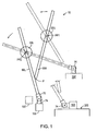
- the apparatus 10 is configured to apply labels such as 5 (see Figs. 7A and 7B ) to parcels 300 moving along a conveyor belt 200.
- the apparatus 10 of the present invention includes a support frame 20, a pair of turntable assemblies 30U, 30L, a corresponding pair of arm assemblies 50U, 50L, similarly corresponding arm assembly drive motors 61U, 61L, a label application head assembly 70, a label printer/supplier 100, and a controlling apparatus 120.
- the support frame 20 supports the pair of two turntable assemblies 30U, 30L.
- Each of the turntable assemblies 30U, 30L supports one of the arm assemblies 50U, 50L, such that each of the arm assemblies 50U, 50L is pivotable about a horizontal axis.
- Each of the arm assemblies is also movable along its longitudinal axis relative to its respective turntable.
- arm assemblies 50U, 50L are attached together in a hinged connection.
- a label application head assembly 70 At one end of one of the arm assemblies is attached a label application head assembly 70. This attachment is a pivoting connection that allows for label application to the horizontal or vertical surfaces of parcels passing thereby.
- the turntable assemblies 30U, 30L are not powered, but instead are "idling" in that they allowed for a relatively free pivoting connection of the arm assemblies 50U, 50L relative to the stationary support frame.
- the linear movement of the arm assemblies 50U, 50L along their longitudinal axis is powered by corresponding arm assembly drive motors 61U, 61L.
- This linear movement is independently controlled by a controlling apparatus 120, such that the label application head assembly can be positioned at various desired locations above a conveyor belt or other supporting surface.
- the Support Frame 20 is The Support Frame 20
- the frame 20 of the assembly 10 is configured to be substantially stationary and configured to be located proximate beside of a conveyor 200.
- the frame 20 is substantially stationary, including frame members such as 21, but includes a portion that is pivotable relative to the main portion of the frame 20. This portion is designated as 22, and shall be referenced as a "breakaway support plate 22".
- This breakaway support plate 22 is configured to support both of the turntables 30U, 30L, as noted above.
- the breakaway support plate 22 is pivotably attached relative to the main portion of the frame proximate pivot point PP.
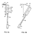
- a tension spring is located at 25 and configures to bias the breakaway support plate 22 in its position such as shown in Fig. 5A .
- the breakaway support plate 22 may pivot from a position shown in Fig. 5A to a position shown in Fig. 5B .
- the breakaway support plate 22 will function. As may be understood, the breakaway support plate 22 "breaks away” from its home position shown in Fig. 5A by pivoting about the pivot point PP; as the force pushes against the label application head assembly 70, this force is transferred from the label application head assembly 70 to both of the upper and lower arm assemblies 50U, 50L. This force is further transferred to the upper and lower turntable assemblies 30U, 30L.
- the force on the label application head assembly 70 causes a moment which causes the breakaway support plate 22 to "break away" to the position shown in Fig. 5B , such that the label application head assembly 70 can move relatively downstream along the conveyor path and upwardly relative to the conveyor 200, thus reducing the risk of damage thereto.
- a sensor 27 (See Fig. 6 ) is provided in operable association with the breakaway support plate 22, such that the overall apparatus 10 (including the system controls) can control other related elements should the sensor recognized that the breakaway support plate 22 has "broken away".
- the motors 61U, 61L, and the conveyor 200 being used with the label applicator could be stopped until the obstruction is cleared or the situation is suitably rectified.
- Fig. 6 illustrates a presence sensor 27. It may also be understood that a detent could also be used at that general location in order to provide an initial breakaway force, if deemed necessary. Under one configuration, no detent is used, and the springs are adjusted so that 4,5 kg (10 pounds) are all that is necessary to deflect the spring and cause the configuration to pivot from the position shown in Fig. 5A to Fig. 5B .
- the upper and lower turntable assemblies 30U, 30L are mounted relative to the surface of the breakaway support plate 22.
- the turntable assemblies each include stationary and rotating portions which are operably connected by turntable bearings such as known in the art.
- the upper turntable assembly 30U includes a stationary inner turntable portion 31U, bearings 32U, and a rotating outer turntable portion 34U.
- the lower turntable assembly 30L includes a stationary inner turntable portion 31L, bearings 32L, and a rotating outer turntable portion 34L.
- the stationary inner turntable portions 31UL, 31L, respectively, are rigidly attached relative to the breakaway support plate 22.
- the rotating outer turntable portions 34U, 34L are allowed to rotate about axes 32UA, 32LA, respectively, which are substantially parallel, and are, in one preferred embodiment, substantially horizontal, assuming the floor supporting the overall system is likewise substantially horizontal.
- axes 32UA, 32LA are substantially parallel, and are, in one preferred embodiment, substantially horizontal, assuming the floor supporting the overall system is likewise substantially horizontal.
- this is one preferred embodiment only and should not be construed as limiting.
- the inner and the outer portions 31U, 34U include corresponding bearing races which contain the turntable bearings 32U.
- linear bearings such as 37U, 37L, with elements 37U shown in Fig. 6 and discussed later, which allow the arm assemblies 50U, 50L, to move linearly along their longitudinal axis relative to the rotating outer turntable portions 34U, 34L, respectively.
- the upper and lower turntable assemblies 30U, 30L include suitable bearings such as known in the art to provide suitable operational and wear characteristics.
- the turntable assemblies are free to rotate about their respective rotational axes, 32UA, 32LA, that is, the bearings supporting them relative to the frame member 21 of the frame 20 allows them to be considered “idling", except that normal frictional drag will be present.
- the upper and lower turntable assemblies 30U, 30L support corresponding upper and lower arm assemblies 50U, 50L, through the use of the rotating outer turntable portions 34U, 34L, which support the upper and lower arm assemblies while allowing them to move along linear paths relative thereto.
- the upper turntable assembly 30U could be referenced as a "first” turntable assembly. It similarly could also be noted that the lower turntable assembly 30L could be referenced as a “second” turntable assembly.
- the upper arm assembly 50U could be referenced as a "first” arm assembly, and the lower arm assembly 50L could be referenced as a “second” arm assembly.
- Other elements may also be referenced as being “first” or “second”. However, these terms are not to be construed as limiting but only to provide an accurate and understandable description of the invention.
- movement of a rotating turntable portion relative to its associated stationary turntable portion shall be understood generally as “turntable rotation”.
- the upper arm assembly 50U includes an upper arm main frame element 51U and also includes an upper cogged belt 53U.
- This cogged belt 53U is not an endless belt, but has upper and lower ends attached relative to the upper and lower ends of the upper arm main frame element 51U, respectively.
- the cogged belt 53U is driven by a drive cog such that tension on the cogged belt causes movement of the upper arm main frame element 51U (which is part of the upper arm assembly 50U) along its linear path.
- the main frame element 51U of the upper arm assembly 50U in one embodiment includes a transverse cross section which could be thought of as being "C"-shaped, as shown in Fig. 10 .
- Fig. 10 is an illustrative view of the transverse cross section of an upper arm main frame element 51U, as it is retained for linear movement relative to a upper linear bearing assembly 36U.
- the upper linear bearing assembly 36U is attached to the rotating outer turntable portion 34U.
- the upper cogged belt 53U is also shown in transverse cross section. However it should be understood that the upper cogged belt 53U could be on either side of the upper arm main frame element 51U. Bearings are not shown between the upper arm main frame element 51U and the T-shaped spinelike portion of the upper linear bearing assembly 36U.
- bearings may be provided therebetween, typically held by races fixed to the member 36U, to allow for the bearings (not shown) to roll on the member 51U and to facilitate linear movement of the member 51U relative to the member 36U, along an axis substantially normal to the sheet of paper bearing the drawing.
- this C-shaped transverse cross section of the main frame element 51U provides a longitudinal channel within which as noted above can be provided bearings as known in the art to facilitate the longitudinal movement of the main frame element 51U of the upper arm assembly 50U along its relatively linear path relative to the rotating outer turntable portion 34U.
- bearings as known in the art to facilitate the longitudinal movement of the main frame element 51U of the upper arm assembly 50U along its relatively linear path relative to the rotating outer turntable portion 34U.
- Such linear bearing configurations are as known in the art and one of any several linear bearing configurations may be used without departing from the present invention.
- an elongate enclosure may be provided along either of the arm frame elements. This elongate enclosure can provide protection for control wires, tubes, etc. which extend to the various elements of the apparatus 10 (See Fig. 1 ) including the label application head assembly 70 (See Fig. 2 ).
- the upper and lower arm assembly drive assemblies 60U, 60L are configured to move the upper and lower arm assemblies 50U, 50L, respectively, along their linear paths relative to the rotating outer turntable portions 34U, 34L, respectively.
- suitable linear bearings are provided as known in the art to facilitate this linear path movement.
- assembly 60U Since the upper and lower arm assembly drive assemblies 60U, 60L are similar in configuration, assembly 60U will be explained by way of example.
- upper arm assembly drive assembly 60U includes an upper motor 61U and an upper gearbox assembly 62U.
- the gearbox assembly 62U includes an upper drive cog 64U and upper idler gears 65U.
- the upper motor 61U drives the gearbox assembly 62U by driving the drive cog 64U such that the upper drive cog 64U drives the upper cogged belt 53U as discussed earlier.
- the upper motor 61U is mounted by a suitable mounting configuration (in one configuration an unshown angled bracket is used) so that it is rigidly mounted relative to the rotating outer turntable portion 34U.
- This motor 61U can be used on its own or can be used with an appropriate reduction box as needed to provide an outlet shaft torque and speed.
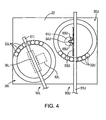
- the gearbox assembly 62U (see Fig. 3 ) has a frame rigidly attached relative to the rotating outer turntable portion 34U.
- the gearbox assembly 62U is driven by the upper motor 61U, such that the upper drive cog 64U is rotatably driven. In actuality there is reduction in the gearbox assembly 62U; the upper drive cog is driven at a 1:4 ratio relative to the motor or motor/reduction assembly driving it.
- the gearbox assembly also includes two upper idler gears 65U (see Fig. 4 ) which are rotatably mounted relative to the frame of the gearbox assembly 62U, and provide guide means for the cogged belt.
- the cogged belt 53U which is not continuous but has discrete ends, has a middle portion threading through the assembly gearbox assembly 62U.
- the ends of the cogged belt 53U are fixed to the upper arm frame element 51U.
- the cogged belt 53U passes along a first of the two idler gears, then substantially around the upper drive cog 64U, and then passes along the second of the two idler gears.
- the upper drive cog 64U drives the belt, it runs relatively along the length of the belt.
- the motor 61U drives the gearbox assembly 62U which has an output shaft (not shown), which drives the drive cog 64U.
- This drive cog 64U drives the cogged belt 53U.
- the motor 61U could be braked as needed by a suitable brake known in the art, to provide a stopping control feature.
- an encoder mechanism is attached relative to the motor, such that feedback can be derived from the motor, effectively providing a servo-controlled motor.
- the motors 61U, 61L are servo-controlled, similar and of fractional horsepower, approximately 1 ⁇ 2 horse power, and is configured to in one embodiment drive the 2,54 cm (one inch) diameter cog sprocket about 1800 rpm.
- the force transferred to the belt was approximately 222 N (50 pounds), to get the acceleration required, although other configurations are contemplated under the present invention.
- the motors include an attached to a reducing assembly, which in one embodiment is a four-to-one reduction ratio.
- the upper and lower arm assembly drive motors 61U, 61L, drive corresponding drive cogs (such as 64U) such that rotation of the shafts of the drive motors causes linear movement of the corresponding arm assemblies 50U , 50L along their longitudinal axis relative to rotating support tables 34U, 34L of the turntable assemblies 30U, 30L.
- the control of the rotation of these drive motors is provided by a control apparatus 120 such as a PLC discussed elsewhere in this application.
- the upper and lower arm assembly drive motors 61U, 61L have bases mounted relative to the rotating support tables 34U, 34L, respectively, of the upper and lower turntable assemblies 30U, 30L, respectively.
- the drive motors 61U, 61L have corresponding drive shafts which support and drive the respective drive cogs 64U, 64L. Therefore it may be seen that the drive cogs 64U, 64L are rotatably driven about an axis that is stationary relative to the respective rotating support tables 34U, 34L, but these axes move around relative to the stationary frame 20.
- the rotating outer turntable portions 34U, 34L, respectively, of the upper turntable assemblies 30U, 30L respectively are essentially in an "idle" mode relative to the supporting frame member 20.
- an arm assembly may move along its longitudinal axis relative to its corresponding rotating support table, the longitudinal axis will not always remain in the same orientation; it will be moved if the rotating support table rotates about its rotational axis.
- the turntable assemblies 30U, 30L support the arm assemblies 50U, 50L at one location along the length of the arm main frame elements (51U, 51L).
- the lower ends of the upper and lower upper arm assemblies 50U, 50L are pivotably attached at a pivot location "P", said pivot location being not at the end but proximate the end of the lower arm assembly 50L, said pivoting connection being substantially horizontal and along an axis parallel to the conveyor direction. This pivot axis is perpendicular to the paper of Fig. 1 .
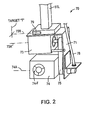
- the label application head assembly 70 is rigidly attached relative to the lower end of the lower arm assembly 50L.
- the label application head assembly 70 includes the following elements: frame 71, servo motor 73, label application member 74, applicator position endless drive belt 75, home position indicator (laser) 79, and various control wires 78.
- the frame 71 of the label applicator assembly 70 is rigidly affixed relative to the lower end of the lower arm main frame element 51L.
- This frame 71 is configured to support the servo motor 73, label application member 74, applicator position endless drive belt 75, home position indicator (laser) 79, and various control wires 78, as noted below.
- the servo motor 73 has its base rigidly mounted relative to the frame 71 of the label applicator assembly 70.
- the servo motor 73 rotatably drives a drive pulley 73P about an axis 73A.
- the label application member 74 is pivotably mounted relative to the frame 71 of the label applicator assembly 70 about an axis 74A. This pivoting relationship, along with the use of suitable servo control, allows for the label application member 74 to be pivoted to a known position relative to the application head assembly 70 and relative to the remainder of the apparatus 10, as needed, in order to attach labels both to vertical surfaces and to horizontal (typically top) surfaces, such as shown generally in Figs. 1 and 7A/7B .
- the endless drive belt 75 is attached both to the drive pulley 73P of the servo motor 73, and the driven pulley 74P of the label applicator 74.
- the angular position of the label applicator 74 can be adjusted as desired.
- the range of the label applicator is approximately 155° relative to the conveyor surface.
- Control of the servo motor 73 is via control wires 78 such as known in the art.
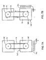
- Figs. 7A and 7B show the pivoting movement of the label application member 74.
- the function of the label application member 74 is to selectively retain a label on its discharge side (directed down in Fig. 7A and directed to the right in Fig. 7B ), and selectively to discharge the label onto a package or other suitable surface proximate the discharge side of the label application member 74.
- the label application head is substantially as known in the art, and provides a function of "picking up” holding a label thereon, and “blowing" the label a distance to a receiving surface, such as a surface of a package.
- the label application member 74 is pivotably attached relative to the frame 71 by bearings such as known in the art, it is supplied with both air and electrical controls which are not all shown for purposes of clarity in illustration.
- the label applicator requires both air and electricity. Air (at a relatively low vacuum pressure provided by a fan) is used for holding the label on label side opening 74-L as needed, and a "blast" of air (from a high pressure source) is used in order to project the label from the grated label side opening 74-L onto an adjacent surface (such as a parcel).
- the label application member includes an air passageway through it from fan side opening 74-F to label side opening 74-L.
- the suction is provided by a fan proximate fan side opening 74-F, which draws air into the label side opening 74-L to hold the labels thereon.
- the blast of air is provided by positive pressure from a pressurized air line out of the label side opening 74-L shown in Figs. 7A and 7B .
- the label application member 74 requires electricity and compressed air.
- an electric fan is for providing suction only.
- a separate positive air pressure in one embodiment 5,5 bar (80 pounds per square inch) is configured for blowing only.
- the label applicator assembly 70 as noted above also includes a home position indicator, which in one embodiment is a laser beam 79B provided by a laser generating member 79. This laser beam is projected onto a stationary location such as the target T shown in Fig. 2 . This allows for the machine operator to initially "zero" the label application head as desired, and also allows for periodic checking of the zero position as desired.
- a home position indicator which in one embodiment is a laser beam 79B provided by a laser generating member 79. This laser beam is projected onto a stationary location such as the target T shown in Fig. 2 . This allows for the machine operator to initially "zero" the label application head as desired, and also allows for periodic checking of the zero position as desired.
- the laser-targeting device may be used as desired, and may not be used if not deemed necessary for preferred function.
- the label generator carries several sensors on it that tells when the head 74 is back at the current position to pick up a new label. It also tells the operator/controller when the printer is in the correct position. It also has a service position when the paper is changed. A "label low indicator" is also provided which sends a signal back to the PLC.
- the blow nozzles point one way, and the suction fan is blowing the other way.
- the suction fan is configured to suck the label onto the head of the label application member, and the blow nozzles send the label to its final destination.
- the label is blown from 7,6 to 20,3 cm (3 to 8 inches) to its destination on a box surface.
- one configuration includes the use of 5,5 bar (80 pounds per square inch) for about 30 milliseconds.
- the suction fan is configured in one embodiment to provide enough force to hold approximately three times the weight of the label, in order to maintain the label on the application head, even if the application head moves with approximately a three "G" force.
- the labels can be blown onto vertical, horizontal, or even inclined surfaces.
- the rotation capability of the label application head assembly should be understood to provide such a capability.
- the label printer and supplier 100 is such as known in the art, and could include a blowing feature, to push the label onto the label application head, just to get it seated until the label applicator holds the label on its own.
- a label printer/supplier is provided at 100.
- This element 100 can be an off-the-shelf item such as can be the conveyor. It should be noted that the distance between the label applicator assembly 70 when receiving a label from the label printer/supplier 100 tends to be more critical than the distance between the label applicator assembly 70 and a parcel side.
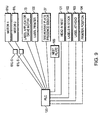
- Figure 9 is a schematic view illustrating the operable connection and association between the control apparatus 120 (shown in one example as including a PLC) the motors 61U, 61L, and their associated servo amps 61U-S, 61L-S, the label applicator drive motor 73, the label printer 100, and the breakaway plate presence sensor 27.
- the servo amps 61U-S, 61L-S provide the necessary function between the control apparatus and the motors as known in the art.
- a "Head in Nest" sensor 101 which is a sensor that recognizes when the label application head assembly 70 is in its "nest” which is the word used to indicate that it is ready to receive labels.
- a "Labels in Stock” sensor 102 which is configured to provide a signal to the PLC 120 that a certain pre-determined number of labels are left in the printer. This can be used for planning purposes; in one embodiment when the label printer 100 is out of labels, it sends a signal to the PLC, but by this time the system has to be stopped.
- a "label at head” sensor 103 which allows the system to know that the label applicator has transferred a label from the printer to the label applicator.
- a "Printer Position” sensor 104 which provides an indication to the overall system that the printer is in its operating position. This is to be distinguished from a service position which may be used when the printer is being serviced or provided with Label stock.
- a "Nest Plate” sensor 105 which is a sensor operably associated with a plate that acts as a last resort damage prevention device to prevent the label application head assembly 70 from colliding with the printer or other devices. This is to address an emergency condition to be avoided, such as if the label applicator has gone too far.
- connection with the label generator is through an Ethernet connection in one preferred embodiment.
- the other connections can be as known in the art.
- the label generator also communicates the data to be printed on the label from the camera process through the PLC and then out to the label generator.
- the PLC that controls the robot functions and the servos and the print generator device and the camera, if the camera is in the system.
- a camera can be used in association with the system in order to provide information to the system 10 sufficient to provide information regarding the position of the packages for receipt of the labels.
- the position of the label applicator assembly 70 of the apparatus 10 is controlled by controlling the upper and lower arm assembly servo drive motors 61U, 61L, and the servo motor 73 of the label applicator assembly 70 itself.
- the apparatus is controlled in a "point-to-point” manner, that is, the machine is controlled to a degree sufficient to get the label applicator assembly 70 from one point to another and the particular path used is not seen as of primary concern.
- This is opposed to a "known path” technique, which sends the label applicator assembly 70 along a known path.
- the desired position is done by determining an " R " and a " Theta " of one of the arm assemblies, in one embodiment, the lower arm assembly 50L. This may be thought of as using polar equations. Attention is first given to the R and Theta of the lower arm assembly, and then the resulting R and Theta of the upper arm assembly is calculated by trigonometry. When these values have been calculated, the motors 61U, 61L are energized to move the label applicator assembly 70 as desired. The servo motor 73 of the label applicator assembly 70 itself is likewise controlled as needed by the use of trigonometric calculations.
- the system uses polar coordinates; in other words, the relative angular position, and the longitudinal movement of the arms are noted.
- the relative angular position of the label application head is also noted.
- the invention under one embodiment also includes the use of what could be described as "equal timing accelerations” where both motors start at the same time, end at the same time, but they also accelerate for the same period of time. So, half of the move is acceleration (the first half), and the second half of the move is deceleration. This has been found to provide a smoother less “jerky” movement.
- Fig. 8 is a graph showing the rotational velocity of various elements of the invention over time.
- the graph shows the rotational velocity of the motor 61U over time, the rotational velocity of the motor 61U over time, and the rotational velocity of the label application assembly's servo motor 73.
- the two motors accelerate simultaneously and for the same period of time, reach their peak velocity at the same time at t 1 , and then start decelerating to stop at the same time, at time t 2 .
- the label application motor may operate differently depending on the amount of rotation needed.
- the "motor" triangles are overlapping in time, but not necessarily overlapping in magnitude.
- the present invention contemplates spending the least amount of time in the field of operation (where the parcel are going by). Instead of "hovering" over the packages as they come by, the label application head 74 is moved out of its home position in as much of a "single motion" as possible, with the arms going out while the head is rotating. Preferably, the label application head is in its desired position before the time the arms have stopped.
- the rotation of the label application head 74 is synchronized to start at the same time as do the servo motors.
- the rotational head is calculated to finish its move in what could be considered the "minimum arm motion" - which means it is not synchronized to end at the same point, necessarily, but is timed to finish its shortest move in time to get the label at its desired position, which is the position at which the label will be dispensed.
- the position is the "shortest move", with the shortest arm move being if the box were right up against the side of the bed.
- the head is set to rotate at a fixed velocity acceleration move every time, such that it's ready at its desired dispensing position when it enters the "action zone", regardless of whether it's going to be dispensed right at the edge of the action zone, or on the other side of it.
- the label application head assembly rotation is not timed to end at the same time the motors stop their movement (see Fig. 8 ), but it is configured in one embodiment to move at a set acceleration independent of the length of the long arm moves. Essentially, it accelerates a constant acceleration every time. Whether it has to move 5 degrees or 105 degrees, it is preferably going to have the same acceleration, regardless.
- the "point-to-point" nature of the device makes it simpler, and it was capable of doing calculations in the PLC within the 10 milliseconds that were provided, which is in one preferred embodiment the PLC update rate. So, this can be done with a PLC, rather than a motion controller, which saves significant expenses.
- the axes 32UA, 32LA could be thought of as first and second “turntable axes", or second and first “turntable axes”, as the case may be.
- pivoting connection between the two arms at P in Fig. 1 could be thought of as lying along an "arm pivoting connection axis". It may also be understood that this "arm pivoting connection axis" is substantially parallel to the turntable axes.
- the conveying surface supporting the exemplary parcels 300 in one embodiment is substantially horizontal and upwardly facing, although other orientations are contemplated under the present invention. If may also be understood that this conveying surface could be thought of as lying in a “conveying plane” which in one embodiment could be considered a "horizontal conveying plane”.
- a turntable or other axis can be "spaced a distance from the closest point of the conveying plane".
- the upper turntable axis 32UA is spaced a certain distance above the conveyor surface, this distance being slightly higher than the distance the lower turntable axis is from the conveying surface.
- Words like “first turntable axis” and “second turntable axis” may be used under allowed practice to differentiate between two turntable axes without necessary identifying which of the upper or lower turntable axes correspond to the first or the second turntable axes.
- the distance between the label application head member 74 and the label printer 100 is preferably about 0,64 cm (1 ⁇ 4 inch), in that the label travels about 0,64 cm (1 ⁇ 4 inch) when being transferred from the printer to the label applicator. It has been found to be fairly critical that the positioning of the label on the label applicator is as close as possible and the inventors have found that a 0,16 cm (1/16-inch) tolerance for this position is preferable. If the label is too much to one side, the travel after it is blown can disadvantageously include a "tumble".
- the label travels approximately 7,6 to 20,3 cm (3 to 8 inches) to the parcel surfaces when being blown from the label application head assembly 70.
- the apparatus and method according to the present invention could be used to apply not only relatively thin adhesive labels, including but not limited those including two-dimensional codes such as Barcode or Maxicode, but could also be used to apply thicker labels, including RFID labels.
- the invention could also be used as a scanner by using a scanner on the head, and manipulating the scanner as desired to pick up bar or other codes at various locations.
Landscapes
- Labeling Devices (AREA)
- Vehicle Interior And Exterior Ornaments, Soundproofing, And Insulation (AREA)
- Cultivation Receptacles Or Flower-Pots, Or Pots For Seedlings (AREA)
- Adhesive Tapes (AREA)
Claims (21)
- Vorrichtung zum Übertragen von Etiketten oder anderen Gegenständen an eine Außenfläche eines Pakets (300), welches längs eines Förderweges transportiert wird, der eine Breite hat und durch eine Förderoberfläche (200) definiert ist, von welcher ein Teil in einer Förderebene liegt, wobei die Pakete horizontale und vertikale Oberflächen haben,
gekennzeichnet durch
einen relativ stationären Rahmen (20),
eine erste Drehtelleranordnung (30U), die ihrerseits aufweist:einen ersten stationären Drehtellerteil (31U), welcher relativ zu dem stationären Rahmen befestigt ist undeinen ersten drehbaren Drehtellerteil (34U), welcher drehbar relativ zu dem ersten stationären Drehtellerteil befestigt ist derart, dass der erste drehbare Drehtellerteil um eine erste Drehtellerachse (32UA) bezüglich des ersten stationären Drehtellerteils und des Rahmens rotieren kann,eine zweite Drehtelleranordnung (30L), die ihrerseits aufweist:einen zweiten stationären Drehtellerteil (31L), welcher relativ zu dem stationären Rahmen befestigt ist undeinen zweiten drehbaren Drehtellerteil (34L), welcher drehbar relativ zu dem zweiten stationären Drehtellerteil befestigt ist derart, dass der zweite drehbare Drehtellerteil um eine zweite Drehtellerachse (32LA) gegenüber dem ersten stationären Drehtellerteil und dem Rahmen rotieren kann,einen ersten länglichen Arm (51U), welcher relativ zu dem ersten drehbaren Drehtellerteil derart montiert ist, dass er eine lineare Bewegung bezüglich des ersten drehbaren Drehtellerteils längs eines ersten linearen Weges im Wesentlichen parallel zur Längsachse des ersten länglichen Arms ausführen kann, wobei jedoch der erste längliche Arm um die erste Drehtellerachse zusammen mit dem ersten drehbaren Drehtellerteil rotieren kann,
einen zweiten länglichen Arm (51L), welcher relativ zu dem zweiten drehbaren Drehtellerteil derart montiert ist, dass er eine lineare Bewegung bezüglich des zweiten drehbaren Drehtellerteils längs eines zweiten linearen Weges im Wesentlichen parallel zur Längsachse des zweiten länglichen Armes ausführen kann, wobei jedoch der zweite längliche Arm um die zweite Drehtellerachse zusammen mit dem zweiten drehbaren Drehtellerteil rotieren kann,
eine Gelenkverbindung (P) zwischen dem ersten und dem zweiten länglichen Arm,
einen ersten Armantrieb (60U) zur Lieferung einer ausreichenden Kraft, um den ersten länglichen Arm sich längs des ersten linearen Weges bezüglich des ersten drehbaren Drehtellerteils bewegen zu lassen,
einen zweiten Armantrieb (60L) zur Lieferung einer ausreichenden Kraft, um den zweiten länglichen Arm sich längs des zweiten linearen Weges bezüglich des zweiten drehbaren Drehtellerteils bewegen zu lassen,
einen Etikettapplikatorkopf (70, 74), der relativ zu einem der beiden länglichen Arme befestigt ist,
so dass der Etikettapplikatorkopf an verschiedene Stellen über der Breite des Transportweges und an unterschiedliche Höhen bezüglich der Transportfläche bewegt werden kann, wobei der Etikettapplikatorkopf betätigbar ist, um Etiketten oder andere Gegenstände auf die Oberflächen von längs der Förderoberfläche beförderten Pakete auszugeben. - Vorrichtung nach Anspruch 1, bei welcher die Befestigung des Etikettapplikatorkopfes eine Schwenkverbindung zwischen dem unteren Ende mindestens eines der länglichen Armglieder und dem Etikettenapplikatorkopf aufweist, so dass Etiketten oder andere Gegenstände sowohl an horizontale wie auch an vertikale Paketoberflächen anbringbar sind.
- Vorrichtung nach Anspruch 1 oder 2, bei welcher die Achse des ersten Drehtellers einen ersten Abstand von dem nächsten Punkt der Transportebene hat und die Achse des zweiten Drehtellers einen zweiten Abstand von dem nächsten Punkt der Transportebene hat und die Etikettenkopfschwenkachse im Wesentlichen parallel zu der ersten und der zweiten Drehtellerachse verläuft,
wobei der Etikettapplikationskopf um die Etikettenkopfschwenkachse manipulierbar ist und gleichzeitig der erste und zweite Armantrieb so betätigbar sind, dass die erste und zweite Armanordnung sich längs erster bzw. zweiter linearer Wege gegenüber dem ersten bzw. zweiten Drehtellerteil bewegen können, wobei der Etikettapplikationskopf in verschiedene geeignete Orientierungen bewegbar ist, um Etiketten oder andere Gegenstand sowohl auf horizontale wie auch vertikale Oberflächen von längs der Förderoberfläche beförderten Pakete auszugeben. - Vorrichtung nach einem der vorstehenden Ansprüche, bei welcher der erste und zweite längliche Arm so ausgebildet sind, dass sie längs linearer Wege gegenüber dem ersten bzw. zweiten drehbaren Drehtellerteil vor und zurück bewegbar sind.
- Vorrichtung nach Anspruch 4, ferner mit einer ersten und einer zweiten Linearlageranordnung (32U, 32L) zur Ermöglichung der linearen Bewegung des ersten und zweiten länglichen Schenkelgliedes längs der Wege.
- Vorrichtung nach Anspruch 1, bei welcher der Etikettapplikatorkopf nahe neben dem Ende des ersten länglichen Arms angebracht ist.
- Vorrichtung nach Anspruch 1, bei welcher die Drehtelleranordnungen nicht angetrieben sind, sondern sich frei bewegen können.
- Vorrichtung nach Anspruch 7, bei welcher der Antrieb für den ersten Arm so ausgelegt ist, dass er eine genügende Kraft liefert, um den ersten und den zweiten Arm sich um die erste und zweite Drehtellerachse drehen zu lassen, wenn der Antrieb für den ersten Arm eine ausreichende Kraft liefert, um den ersten Arm sich längs des ersten linearen Weges gegenüber dem ersten drehbaren Drehtellerteil bewegen zu lassen.
- Vorrichtung nach Anspruch 1, weiterhin mit einer zum Steuern des ersten oder zweiten Armantriebs ausgelegten Steuereinrichtung (120) derart, dass in einem Betriebsmodus der Vorrichtung der Betrieb des ersten Armantriebs, jedoch nicht des zweiten Armantriebs, den ersten länglichen Arm sich längs eines linearen Weges gegenüber dem ersten stationären Drehtellerteil bewegen lässt, ferner beide drehbaren Drehtellerteile rotieren lässt und den Etikettapplikatorkopf um die zweite Drehtellerachse rotieren lässt.
- Vorrichtung nach Anspruch 9, bei welcher der erste und der zweite drehbare Drehtellerteil während der Bewegung des Etikettapplikatorkopfes sich in gleicher oder entgegengesetzter Richtung drehen.
- Vorrichtung nach Anspruch 3, bei welcher der erste und der zweite Armantrieb so ausgelegt sind,
dass der Betrieb des ersten Armantriebs, nicht jedoch des zweiten Armantriebs, die Achse der Schwenkverbindung zwischen den beiden Armen um die zweite Drehtellerachse schwenken lässt,
und dass die Betätigung des zweiten Armantriebs, nicht jedoch des ersten Armantriebs, die Achse der Schwenkverbindung zwischen den beiden Armen um die erste Drehtellerachse schwenken lässt,
und dass ein kombinierter Betrieb des ersten und zweiten Armantriebs die Achse der Schwenkverbindung zwischen den beiden Armen sich gegenüber den beiden Drehtellerachsen bewegen lässt. - Vorrichtung nach Anspruch 3, bei welcher der erste und der zweite Armantrieb so ausgelegt sind, dass ihr Betrieb in Kombination mit dem Schwenken des Etikettapplikatorkopfes das Anbringen von Etiketten in einer Mehrzahl von Richtungen über einen Bereich von mehr als 90° erlaubt.
- Vorrichtung nach Anspruch 3, bei welcher der Etikettapplikatorkopf so ausgebildet ist, dass er Etiketten an die vertikalen Seiten von Paketen oder an die horizontalen Oberseiten von Paketen aufbringt, wenn diese entlang des Förderweges laufen.
- Vorrichtung nach Anspruch 13, ferner mit einem so ausgelegten Motor (73) dass er die Drehung des Etikettapplikatorkopfes gegenüber dem ersten oder zweiten Tragarmglied steuert.
- Vorrichtung nach Anspruch 14, bei welcher der Motor ein servogesteuerter Motor (73) ist.
- Vorrichtung nach Anspruch 3, bei welcher der Etikettapplikatorkopf so ausgebildet ist, dass er Etiketten aufnimmt und abgibt, und weiterhin mit einem derart ausgebildeten Etikettenzulieferer (100), dass er ein Etikett an den Etikettapplikatorkopf abgibt.
- Vorrichtung nach Anspruch 16, weiterhin mit einer Steuereinrichtung (120), welche dem ersten und dem zweiten Motor und dem Etikettapplikatorkopf betriebsmäßig so zugeordnet ist, dass die Arme in zwei Positionen bewegbar sind, wobei in der ersten Position der Etikettapplikatorkopf eine Position einnimmt, in welcher eine Etikettübernahme von dem Etikettlieferer zum Etikettapplikatorkopf möglich ist, und in der zweiten Position der Etikettapplikatorkopf eine Lage einnimmt, in welcher die Etikettübernahme von dem Etikettapplikatorkopf zu einem auf dem Förderer befindlichen Paket möglich ist.
- Vorrichtung nach Anspruch 3, bei welchem dem Etikettapplikatorkopf Druckluft zugeführt wird, um ein kräftiges Blasen des Etiketts vom Etikettapplikatorkopf zu erlauben, wobei dieser Kopf ferner einen elektrischen Ventilator enthält, um ein Festhalten von Etiketten am Etikettapplikatorkopf durch Vakuum zu erlauben.
- Vorrichtung nach Anspruch 3, ferner mit
einer ersten Länglicharmanordnung (50U), welche einen ersten länglichen Arm und einen ersten Zahnriemen (53U) enthält, der längs verläuft und mit seinen Enden an dem ersten länglichen Arm angebracht ist,
zweitens einer zweiten Länglicharmanordnung (50L), die einen zweiten länglichen Arm und einen zweiten Zahnriemen (53L) enthält, welcher längs verläuft und mit seinen Enden an dem zweiten länglichen Arm angebracht ist, und
wobei der erste Armantrieb seinerseits aufweist:einen ersten Motor (61U) undeinen ersten Antriebszahn (460U),wobei der erste Antriebszahn so konfiguriert ist, dass er in den ersten Zahnriemen der ersten Länglicharmanordnung eingreift, und der erste Motor so ausgelegt ist, dass er den Antriebszahn so antreibt, dass er eine genügende Kraft liefert, um den ersten länglichen Arm längs des ersten linearen Weges gegenüber dem ersten drehbaren Drehtellerteil zu bewegen,
und wobei der zweite Armantrieb seinerseits aufweist:einen zweiten Motor (61 L) undeinen zweiten Antriebszahn (64L),wobei der zweite Antriebszahn so konfiguriert ist, dass er in den zweiten Zahnriemen der ersten Länglicharmanordnung eingreift, und wobei der zweite Motor so ausgelegt ist, dass er den zweiten Antriebszahn so antreibt, dass er eine ausreichende kraft liefert, um den zweiten länglichen Arm längs des zweiten linearen Weges gegenüber dem zweiten drehbaren Drehtellerteil zu bewegen. - Verfahren zum Übertragen von Etiketten oder anderen Gegenständen an eine äußere Oberfläche von Paketen (300), welche längs eines Förderweges befördert werden, der eine Breite aufweist und durch eine Förderoberfläche (200) definiert ist, von der ein Teil in einer Förderebene liegt, wobei die Pakete horizontale und vertikale Oberflächen haben, mit den Schritten:Vorsehen eines relativ stationären Rahmens (20),Vorsehen einer ersten Drehtelleranordnung (30U), die ihrerseits aufweist
einen ersten stationären Drehtellerteil (31U), der relativ zu dem stationären Rahmen befestigt ist und
einen ersten drehbaren Drehtellerteil (34U), der drehbar relativ zu dem ersten stationären Drehtellerteil befestigt ist derart, dass der erste drehbare Drehtellerteil um eine erste Drehtellerachse (32UA) gegenüber dem ersten stationären Drehtellerteil und dem Rahmen rotieren kann,Vorsehen einer zweiten Drehtelleranordnung (30L), die ihrerseits aufweist:einen ersten stationären Drehtellerteil (31L), der relativ zu dem stationären Rahmen befestigt ist undeinen zweiten drehbaren Drehtellerteil (34L), der drehbar relativ zu dem zweiten stationären Drehtellerteil befestigt ist derart, dass der zweite drehbare Drehtellerteil um eine zweite Drehtellerachse (32LA) gegenüber dem ersten stationären Drehtellerteil und dem Rahmen rotieren kann,Vorsehen eines ersten länglichen Armes (51U), der relativ zu dem ersten drehbaren Drehtellerteil montiert ist, um eine lineare Bewegung des ersten länglichen Armes gegenüber dem ersten drehbaren Drehtellerteil längs eines ersten linearen Weges zu erlauben, der im Wesentlichen parallel zu der Längsachse des ersten länglichen Armes verläuft, wobei jedoch der erste längliche Arm um die erste Drehtellerachse zusammen mit dem ersten drehbaren Drehtellerteil rotieren kann,Vorsehen eines zweiten länglichen Arms (51L), der relativ zu dem zweiten drehbaren Drehtellerteil montiert ist derart, dass eine lineare Bewegung des zweiten länglichen Armes relativ zu dem zweiten drehbaren Drehtellerteil längs eines zweiten linearen Weges möglich ist, der parallel zu der Längsachse des zweiten länglichen Armes verläuft, wobei jedoch der zweite längliche Arm auch um die zweite Drehtellerachse zusammen mit dem zweiten drehbaren Drehtellerteil rotieren kann,Vorsehen einer Schwenkverbindung (P), zwischen dem ersten und zweiten länglichen Arm,Vorsehen eines ersten Armantriebs (60U) zur Lieferung einer ausreichenden Kraft, um den ersten länglichen Arm längs des ersten linearen Weges gegenüber dem ersten drehbaren Drehtellerteil bewegen zu lassen,Vorsehen eines zweiten Armantriebs (60L) zur Lieferung einer ausreichenden Kraft, um den zweiten länglichen Arm längs des zweiten linearen Weges gegenüber dem ersten drehbaren Drehtellerteil bewegen zu lassen,Vorsehen eines Etikettapplikatorkopfes (70, 74), der schwenkbar relativ zu einem der beiden länglichen Arme angebracht ist,Bewegen des Etikettapplikatorkopfes um seine Achse bei gleichzeitiger Betätigung des ersten und zweiten Armantriebs derart, dass die erste und die zweite Armanordnung sich längs des ersten bzw. zweiten linearen Weges gegenüber dem ersten bzw. zweiten drehbaren Drehtellerteil bewegen,Bewegen des Etikettapplikatorkopfes an verschiedene Stellen über der Breite des Förderweges und in unterschiedlichen Höhen gegenüber der Förderoberfläche undManipulieren des Etikettapplikatorkopfes in unterschiedliche geeignete Orientierungen zur Abgabe von Etiketten oder anderen Gegenständen auf sowohl horizontale wie auch vertikale Oberflächen von Paketen, die längs der Förderoberfläche befördert werden. - Verfahren nach Anspruch 20, bei welchem der erste und der zweite Armantrieb so gesteuert werden, dass sie eine ausreichende Kraft liefern, um den ersten und zweiten länglichen Arm zu näherungsweise der gleichen Zeit zu beschleunigen und zu verlangsamen.
Applications Claiming Priority (2)
| Application Number | Priority Date | Filing Date | Title |
|---|---|---|---|
| US10/855,997 US7343953B2 (en) | 2004-05-28 | 2004-05-28 | Method and application for applying labels on surfaces of selected surfaces of varying orientations |
| PCT/US2005/014264 WO2005118406A1 (en) | 2004-05-28 | 2005-04-25 | Applying labels on surfaces of various orientations |
Publications (2)
| Publication Number | Publication Date |
|---|---|
| EP1753661A1 EP1753661A1 (de) | 2007-02-21 |
| EP1753661B1 true EP1753661B1 (de) | 2009-01-07 |
Family
ID=34967394
Family Applications (1)
| Application Number | Title | Priority Date | Filing Date |
|---|---|---|---|
| EP05740326A Expired - Lifetime EP1753661B1 (de) | 2004-05-28 | 2005-04-25 | Anbringen von etiketten auf flächen verschiedener ausrichtungen |
Country Status (10)
| Country | Link |
|---|---|
| US (2) | US7343953B2 (de) |
| EP (1) | EP1753661B1 (de) |
| JP (1) | JP2008500245A (de) |
| CN (1) | CN100455486C (de) |
| AT (1) | ATE420027T1 (de) |
| CA (1) | CA2540929C (de) |
| DE (1) | DE602005012257D1 (de) |
| ES (1) | ES2320357T3 (de) |
| MX (1) | MXPA06004330A (de) |
| WO (1) | WO2005118406A1 (de) |
Families Citing this family (20)
| Publication number | Priority date | Publication date | Assignee | Title |
|---|---|---|---|---|
| GB2435256A (en) * | 2006-02-15 | 2007-08-22 | Markem Tech Ltd | Label attachment in both of two directions |
| DE102006062511A1 (de) * | 2006-12-29 | 2008-07-03 | Krones Ag | Etikettieraggregat |
| DE102009018561A1 (de) * | 2009-04-24 | 2010-10-28 | Focke & Co.(Gmbh & Co. Kg) | Vorrichtung und Verfahren zum Herstellen von Packungen für Zigaretten |
| HK1151946A2 (en) * | 2010-12-17 | 2012-02-10 | 周大福珠宝金行(深圳)有限公司 | Method, apparatus and device for automatically fabricating ornament tag |
| CN102991790A (zh) * | 2012-10-18 | 2013-03-27 | 苏州一致电子制程有限公司 | 多角度贴标签的机械手 |
| JP6210708B2 (ja) * | 2013-04-19 | 2017-10-11 | 株式会社イシダ | ラベル貼付装置及びラベル貼付方法 |
| CN103425951B (zh) * | 2013-08-05 | 2016-05-11 | 南昌大学 | 有源射频识别电子标签室内通信区域的定位系统及方法 |
| CN103455903A (zh) * | 2013-09-03 | 2013-12-18 | 金东纸业(江苏)股份有限公司 | 纸卷分配输送方法 |
| CN104029876B (zh) * | 2014-05-30 | 2016-05-04 | 东莞市科展电子科技有限公司 | 多功能贴标机 |
| DE102014119391C5 (de) | 2014-12-22 | 2019-02-28 | Espera-Werke Gmbh | Vorrichtung und Verfahren zum Etikettieren von einzelnen Packungen |
| JP6507694B2 (ja) * | 2015-02-09 | 2019-05-08 | 株式会社寺岡精工 | 貼付装置、および貼付装置を備えた包装装置 |
| CN105083665B (zh) * | 2015-08-29 | 2017-09-08 | 深圳市强瑞电子有限公司 | 兼容不同规格的多方位贴标设备及其贴标方法 |
| DE102015117533A1 (de) | 2015-10-15 | 2017-04-20 | Espera-Werke Gmbh | Vorrichtung und Verfahren zum Etikettieren von einzelnen Packungen |
| CN105314191B (zh) * | 2015-11-27 | 2018-01-26 | 芜湖银星汽车零部件有限公司 | 一种自动粘贴标识的装置 |
| CN105539972B (zh) * | 2016-01-26 | 2018-11-06 | 张雪 | 标签上签机及标签上签方法 |
| IT201700096344A1 (it) * | 2017-08-28 | 2019-02-28 | Scm Group Spa | Dispositivo per l’applicazione di etichette per macchine utensili. |
| US11465796B2 (en) * | 2019-02-15 | 2022-10-11 | Id Technology Llc | High speed dual label applicator |
| JP7510147B2 (ja) * | 2020-04-06 | 2024-07-03 | 株式会社寺岡精工 | ラベル貼付システム |
| CN112061537B (zh) * | 2020-09-28 | 2022-04-05 | 中山市松联电子科技有限公司 | 一种转盘式全自动贴标装置 |
| US12145763B2 (en) * | 2020-12-10 | 2024-11-19 | United Parcel Service Of America, Inc. | Label applicator for varied surfaces |
Family Cites Families (26)
| Publication number | Priority date | Publication date | Assignee | Title |
|---|---|---|---|---|
| US1675692A (en) * | 1927-07-02 | 1928-07-03 | American Mach & Foundry | Machine for labeling circular articles |
| US3984227A (en) | 1970-03-23 | 1976-10-05 | Ppg Industries, Inc. | Ammonia solutions of sodium azide |
| US4108710A (en) | 1972-02-14 | 1978-08-22 | B & H Manufacturing Company, Inc. | Apparatus for applying labels to containers |
| DE2314715C3 (de) * | 1973-03-24 | 1975-10-02 | Flachglas Ag Delog-Detag, 8510 Fuerth | Vorrichtung zur Herstellung von Ganzglasdoppelscheiben wechselnder Höhe durch Verschweißender Kanten innerhalb eines Tunnelofens |
| US3984277A (en) | 1972-09-15 | 1976-10-05 | Compac Corporation | Label applicator |
| DE2324412C3 (de) * | 1973-05-15 | 1979-10-25 | Jagenberg-Werke Ag, 4000 Duesseldorf | Verfahren und Vorrichtung zum Aufbringen von beleimten Folienzuschnitten auf Flaschen |
| CA1155806A (en) | 1978-12-05 | 1983-10-25 | Martin Malthouse | Labelling equipment |
| US4676859A (en) | 1981-09-28 | 1987-06-30 | Labeling Systems, Inc. | Labeling apparatus |
| US4397709A (en) | 1982-08-26 | 1983-08-09 | Njm, Inc. | Labeling machine |
| US4526648A (en) | 1983-03-02 | 1985-07-02 | Video Design Pty. Ltd. | Airjet label applicator |
| JPS6169534A (ja) * | 1984-09-11 | 1986-04-10 | 株式会社 サト− | ラベル自動貼付機 |
| US4544431A (en) | 1985-02-06 | 1985-10-01 | Stackpole Limited | Roll fed labelling machine |
| US4784714A (en) | 1986-02-10 | 1988-11-15 | Ricoh Electronics, Inc. | Linerless thermal label printer and applicator |
| GB2294919B (en) * | 1994-09-23 | 1998-11-11 | Labfax Systems Ltd | Apparatus for applying labels to moving articles |
| CA2188624C (en) * | 1995-10-24 | 2004-03-02 | Frederick P. Floyd | Flexible tape applicator and method of operation |
| DE19545191A1 (de) | 1995-12-04 | 1997-06-05 | Siemens Nixdorf Inf Syst | Vorrichtung zum Bereitstellen und Applizieren von Etiketten und Verfahren zum Betrieb dieser Vorrichtung |
| GB9604568D0 (en) * | 1996-03-04 | 1996-05-01 | Markem Syst Ltd | Label applicator |
| GB9609379D0 (en) * | 1996-05-03 | 1996-07-10 | Willett Int Ltd | Mechanism and method |
| DE19642110C2 (de) | 1996-10-12 | 1998-11-26 | Siemens Ag | Verfahren und Vorrichtung zum Etikettieren von flachen Sendungen |
| US5855710A (en) | 1996-11-12 | 1999-01-05 | Trine Labeling Systems | Method and apparatus for labeling containers |
| US5858168A (en) | 1997-02-03 | 1999-01-12 | Trine Labeling Systems | Method and apparatus using enhanced air blow for labeling containers |
| CA2391559C (en) | 1999-11-16 | 2007-02-20 | United States Postal Service | Electromagnetic postal indicia and method of applying same |
| ITBO20000517A1 (it) * | 2000-09-07 | 2002-03-07 | Gd Spa | Metodo ed unita' di applicazione di etichette |
| US6596105B2 (en) | 2001-05-03 | 2003-07-22 | Rock-Tenn Company | High-speed label applicator |
| US20020168212A1 (en) | 2001-05-09 | 2002-11-14 | Nedblake Greydon W. | On-demand label applicator system |
| ITBO20030471A1 (it) * | 2003-08-01 | 2005-02-02 | Gd Spa | Metodo e dispositivo per l'applicazione di un'etichetta ad un pacchetto. |
-
2004
- 2004-05-28 US US10/855,997 patent/US7343953B2/en active Active
-
2005
- 2005-04-25 CN CNB2005800012277A patent/CN100455486C/zh not_active Expired - Fee Related
- 2005-04-25 MX MXPA06004330A patent/MXPA06004330A/es active IP Right Grant
- 2005-04-25 AT AT05740326T patent/ATE420027T1/de not_active IP Right Cessation
- 2005-04-25 CA CA002540929A patent/CA2540929C/en not_active Expired - Lifetime
- 2005-04-25 DE DE602005012257T patent/DE602005012257D1/de not_active Expired - Lifetime
- 2005-04-25 ES ES05740326T patent/ES2320357T3/es not_active Expired - Lifetime
- 2005-04-25 JP JP2007515094A patent/JP2008500245A/ja not_active Withdrawn
- 2005-04-25 EP EP05740326A patent/EP1753661B1/de not_active Expired - Lifetime
- 2005-04-25 WO PCT/US2005/014264 patent/WO2005118406A1/en not_active Ceased
-
2008
- 2008-01-18 US US12/016,523 patent/US7442269B2/en not_active Expired - Lifetime
Also Published As
| Publication number | Publication date |
|---|---|
| US20080110915A1 (en) | 2008-05-15 |
| ES2320357T3 (es) | 2009-05-21 |
| US7442269B2 (en) | 2008-10-28 |
| MXPA06004330A (es) | 2006-06-05 |
| ATE420027T1 (de) | 2009-01-15 |
| CA2540929C (en) | 2008-07-22 |
| EP1753661A1 (de) | 2007-02-21 |
| CN1878698A (zh) | 2006-12-13 |
| WO2005118406A1 (en) | 2005-12-15 |
| US7343953B2 (en) | 2008-03-18 |
| CA2540929A1 (en) | 2005-12-15 |
| JP2008500245A (ja) | 2008-01-10 |
| US20050263535A1 (en) | 2005-12-01 |
| DE602005012257D1 (de) | 2009-02-26 |
| CN100455486C (zh) | 2009-01-28 |
Similar Documents
| Publication | Publication Date | Title |
|---|---|---|
| US7442269B2 (en) | Method and application for applying labels on surfaces of selected surfaces of varying orientations | |
| US8490775B2 (en) | Multiplex grouping device | |
| US6080250A (en) | Device for preparing and applying labels and a method of operation thereof | |
| EP2143083B1 (de) | Freisetzungssystem | |
| CA2194152C (en) | Moveable label printer-applicator/conveyor loader assembly | |
| US20050077418A1 (en) | Reeled material splicing method and apparatus | |
| JPH04502896A (ja) | モジュール式の搬送装置 | |
| US6412535B1 (en) | Label application unit | |
| CA2296081C (en) | Label transfer system for labels cut off a linerless web by a laser | |
| CN108473223A (zh) | 用于给各个包装加标签的装置和方法 | |
| EP0011967A1 (de) | Etikettiermaschinen | |
| US5024718A (en) | Label applying apparatus | |
| AU670091B2 (en) | Movable label printer-applicator assembly | |
| JP2777528B2 (ja) | ラベル貼り付け装置 | |
| JPH11504604A (ja) | ラベル貼付装置 | |
| US6817287B2 (en) | System for applying printed information to a package | |
| DK3271254T3 (en) | DEVICE AND PROCEDURE FOR LABELING OF SINGLE PACKAGES | |
| CA2335935A1 (en) | Labelling apparatus and method thereof | |
| JP3589541B2 (ja) | 搬送コンベアにおける搬送物の停止装置及び該搬送物の方向転換装置 | |
| JP3255880B2 (ja) | カップ式自動販売機のカップ搬送装置 | |
| JPH0115627Y2 (de) | ||
| KR100614691B1 (ko) | 로터리타입 라벨부착기 | |
| EP0734344A1 (de) | Regelungsmittel zur regelung der geschwindigkeit und spannung eines etikettenbandes | |
| WO2024028322A1 (en) | A label applicator arrangement and method | |
| JPH0430505Y2 (de) |
Legal Events
| Date | Code | Title | Description |
|---|---|---|---|
| PUAI | Public reference made under article 153(3) epc to a published international application that has entered the european phase |
Free format text: ORIGINAL CODE: 0009012 |
|
| 17P | Request for examination filed |
Effective date: 20061221 |
|
| AK | Designated contracting states |
Kind code of ref document: A1 Designated state(s): AT BE BG CH CY CZ DE DK EE ES FI FR GB GR HU IE IS IT LI LT LU MC NL PL PT RO SE SI SK TR |
|
| DAX | Request for extension of the european patent (deleted) | ||
| GRAP | Despatch of communication of intention to grant a patent |
Free format text: ORIGINAL CODE: EPIDOSNIGR1 |
|
| GRAS | Grant fee paid |
Free format text: ORIGINAL CODE: EPIDOSNIGR3 |
|
| GRAA | (expected) grant |
Free format text: ORIGINAL CODE: 0009210 |
|
| AK | Designated contracting states |
Kind code of ref document: B1 Designated state(s): AT BE BG CH CY CZ DE DK EE ES FI FR GB GR HU IE IS IT LI LT LU MC NL PL PT RO SE SI SK TR |
|
| REG | Reference to a national code |
Ref country code: GB Ref legal event code: FG4D |
|
| REG | Reference to a national code |
Ref country code: CH Ref legal event code: EP |
|
| REG | Reference to a national code |
Ref country code: IE Ref legal event code: FG4D |
|
| REF | Corresponds to: |
Ref document number: 602005012257 Country of ref document: DE Date of ref document: 20090226 Kind code of ref document: P |
|
| REG | Reference to a national code |
Ref country code: ES Ref legal event code: FG2A Ref document number: 2320357 Country of ref document: ES Kind code of ref document: T3 |
|
| PG25 | Lapsed in a contracting state [announced via postgrant information from national office to epo] |
Ref country code: NL Free format text: LAPSE BECAUSE OF FAILURE TO SUBMIT A TRANSLATION OF THE DESCRIPTION OR TO PAY THE FEE WITHIN THE PRESCRIBED TIME-LIMIT Effective date: 20090107 Ref country code: SI Free format text: LAPSE BECAUSE OF FAILURE TO SUBMIT A TRANSLATION OF THE DESCRIPTION OR TO PAY THE FEE WITHIN THE PRESCRIBED TIME-LIMIT Effective date: 20090107 |
|
| NLV1 | Nl: lapsed or annulled due to failure to fulfill the requirements of art. 29p and 29m of the patents act | ||
| PG25 | Lapsed in a contracting state [announced via postgrant information from national office to epo] |
Ref country code: FI Free format text: LAPSE BECAUSE OF FAILURE TO SUBMIT A TRANSLATION OF THE DESCRIPTION OR TO PAY THE FEE WITHIN THE PRESCRIBED TIME-LIMIT Effective date: 20090107 Ref country code: LT Free format text: LAPSE BECAUSE OF FAILURE TO SUBMIT A TRANSLATION OF THE DESCRIPTION OR TO PAY THE FEE WITHIN THE PRESCRIBED TIME-LIMIT Effective date: 20090107 |
|
| PG25 | Lapsed in a contracting state [announced via postgrant information from national office to epo] |
Ref country code: PT Free format text: LAPSE BECAUSE OF FAILURE TO SUBMIT A TRANSLATION OF THE DESCRIPTION OR TO PAY THE FEE WITHIN THE PRESCRIBED TIME-LIMIT Effective date: 20090608 Ref country code: SE Free format text: LAPSE BECAUSE OF FAILURE TO SUBMIT A TRANSLATION OF THE DESCRIPTION OR TO PAY THE FEE WITHIN THE PRESCRIBED TIME-LIMIT Effective date: 20090407 Ref country code: PL Free format text: LAPSE BECAUSE OF FAILURE TO SUBMIT A TRANSLATION OF THE DESCRIPTION OR TO PAY THE FEE WITHIN THE PRESCRIBED TIME-LIMIT Effective date: 20090107 Ref country code: IS Free format text: LAPSE BECAUSE OF FAILURE TO SUBMIT A TRANSLATION OF THE DESCRIPTION OR TO PAY THE FEE WITHIN THE PRESCRIBED TIME-LIMIT Effective date: 20090507 Ref country code: AT Free format text: LAPSE BECAUSE OF FAILURE TO SUBMIT A TRANSLATION OF THE DESCRIPTION OR TO PAY THE FEE WITHIN THE PRESCRIBED TIME-LIMIT Effective date: 20090107 |
|
| PG25 | Lapsed in a contracting state [announced via postgrant information from national office to epo] |
Ref country code: CZ Free format text: LAPSE BECAUSE OF FAILURE TO SUBMIT A TRANSLATION OF THE DESCRIPTION OR TO PAY THE FEE WITHIN THE PRESCRIBED TIME-LIMIT Effective date: 20090107 Ref country code: EE Free format text: LAPSE BECAUSE OF FAILURE TO SUBMIT A TRANSLATION OF THE DESCRIPTION OR TO PAY THE FEE WITHIN THE PRESCRIBED TIME-LIMIT Effective date: 20090107 Ref country code: DK Free format text: LAPSE BECAUSE OF FAILURE TO SUBMIT A TRANSLATION OF THE DESCRIPTION OR TO PAY THE FEE WITHIN THE PRESCRIBED TIME-LIMIT Effective date: 20090107 |
|
| PLBE | No opposition filed within time limit |
Free format text: ORIGINAL CODE: 0009261 |
|
| STAA | Information on the status of an ep patent application or granted ep patent |
Free format text: STATUS: NO OPPOSITION FILED WITHIN TIME LIMIT |
|
| PG25 | Lapsed in a contracting state [announced via postgrant information from national office to epo] |
Ref country code: RO Free format text: LAPSE BECAUSE OF FAILURE TO SUBMIT A TRANSLATION OF THE DESCRIPTION OR TO PAY THE FEE WITHIN THE PRESCRIBED TIME-LIMIT Effective date: 20090107 Ref country code: SK Free format text: LAPSE BECAUSE OF FAILURE TO SUBMIT A TRANSLATION OF THE DESCRIPTION OR TO PAY THE FEE WITHIN THE PRESCRIBED TIME-LIMIT Effective date: 20090107 |
|
| REG | Reference to a national code |
Ref country code: CH Ref legal event code: PL |
|
| 26N | No opposition filed |
Effective date: 20091008 |
|
| PG25 | Lapsed in a contracting state [announced via postgrant information from national office to epo] |
Ref country code: LI Free format text: LAPSE BECAUSE OF NON-PAYMENT OF DUE FEES Effective date: 20090430 Ref country code: CH Free format text: LAPSE BECAUSE OF NON-PAYMENT OF DUE FEES Effective date: 20090430 Ref country code: BG Free format text: LAPSE BECAUSE OF FAILURE TO SUBMIT A TRANSLATION OF THE DESCRIPTION OR TO PAY THE FEE WITHIN THE PRESCRIBED TIME-LIMIT Effective date: 20090407 |
|
| REG | Reference to a national code |
Ref country code: IE Ref legal event code: MM4A |
|
| PG25 | Lapsed in a contracting state [announced via postgrant information from national office to epo] |
Ref country code: IE Free format text: LAPSE BECAUSE OF NON-PAYMENT OF DUE FEES Effective date: 20090425 Ref country code: MC Free format text: LAPSE BECAUSE OF NON-PAYMENT OF DUE FEES Effective date: 20090430 |
|
| PG25 | Lapsed in a contracting state [announced via postgrant information from national office to epo] |
Ref country code: GR Free format text: LAPSE BECAUSE OF FAILURE TO SUBMIT A TRANSLATION OF THE DESCRIPTION OR TO PAY THE FEE WITHIN THE PRESCRIBED TIME-LIMIT Effective date: 20090408 |
|
| PG25 | Lapsed in a contracting state [announced via postgrant information from national office to epo] |
Ref country code: IT Free format text: LAPSE BECAUSE OF NON-PAYMENT OF DUE FEES Effective date: 20090425 |
|
| PG25 | Lapsed in a contracting state [announced via postgrant information from national office to epo] |
Ref country code: LU Free format text: LAPSE BECAUSE OF NON-PAYMENT OF DUE FEES Effective date: 20090425 |
|
| PG25 | Lapsed in a contracting state [announced via postgrant information from national office to epo] |
Ref country code: HU Free format text: LAPSE BECAUSE OF FAILURE TO SUBMIT A TRANSLATION OF THE DESCRIPTION OR TO PAY THE FEE WITHIN THE PRESCRIBED TIME-LIMIT Effective date: 20090708 |
|
| PGRI | Patent reinstated in contracting state [announced from national office to epo] |
Ref country code: IT Effective date: 20110616 |
|
| PG25 | Lapsed in a contracting state [announced via postgrant information from national office to epo] |
Ref country code: TR Free format text: LAPSE BECAUSE OF FAILURE TO SUBMIT A TRANSLATION OF THE DESCRIPTION OR TO PAY THE FEE WITHIN THE PRESCRIBED TIME-LIMIT Effective date: 20090107 |
|
| PG25 | Lapsed in a contracting state [announced via postgrant information from national office to epo] |
Ref country code: CY Free format text: LAPSE BECAUSE OF FAILURE TO SUBMIT A TRANSLATION OF THE DESCRIPTION OR TO PAY THE FEE WITHIN THE PRESCRIBED TIME-LIMIT Effective date: 20090107 |
|
| REG | Reference to a national code |
Ref country code: FR Ref legal event code: PLFP Year of fee payment: 12 |
|
| REG | Reference to a national code |
Ref country code: FR Ref legal event code: PLFP Year of fee payment: 13 |
|
| REG | Reference to a national code |
Ref country code: FR Ref legal event code: PLFP Year of fee payment: 14 |
|
| PGFP | Annual fee paid to national office [announced via postgrant information from national office to epo] |
Ref country code: FR Payment date: 20230309 Year of fee payment: 19 |
|
| PGFP | Annual fee paid to national office [announced via postgrant information from national office to epo] |
Ref country code: IT Payment date: 20230310 Year of fee payment: 19 Ref country code: GB Payment date: 20230302 Year of fee payment: 19 Ref country code: BE Payment date: 20230315 Year of fee payment: 19 |
|
| PGFP | Annual fee paid to national office [announced via postgrant information from national office to epo] |
Ref country code: ES Payment date: 20230511 Year of fee payment: 19 Ref country code: DE Payment date: 20230307 Year of fee payment: 19 |
|
| REG | Reference to a national code |
Ref country code: DE Ref legal event code: R119 Ref document number: 602005012257 Country of ref document: DE |
|
| GBPC | Gb: european patent ceased through non-payment of renewal fee |
Effective date: 20240425 |
|
| REG | Reference to a national code |
Ref country code: BE Ref legal event code: MM Effective date: 20240430 |
|
| PG25 | Lapsed in a contracting state [announced via postgrant information from national office to epo] |
Ref country code: DE Free format text: LAPSE BECAUSE OF NON-PAYMENT OF DUE FEES Effective date: 20241105 |
|
| PG25 | Lapsed in a contracting state [announced via postgrant information from national office to epo] |
Ref country code: BE Free format text: LAPSE BECAUSE OF NON-PAYMENT OF DUE FEES Effective date: 20240430 |
|
| PG25 | Lapsed in a contracting state [announced via postgrant information from national office to epo] |
Ref country code: GB Free format text: LAPSE BECAUSE OF NON-PAYMENT OF DUE FEES Effective date: 20240425 |
|
| PG25 | Lapsed in a contracting state [announced via postgrant information from national office to epo] |
Ref country code: FR Free format text: LAPSE BECAUSE OF NON-PAYMENT OF DUE FEES Effective date: 20240430 |
|
| PG25 | Lapsed in a contracting state [announced via postgrant information from national office to epo] |
Ref country code: GB Free format text: LAPSE BECAUSE OF NON-PAYMENT OF DUE FEES Effective date: 20240425 Ref country code: FR Free format text: LAPSE BECAUSE OF NON-PAYMENT OF DUE FEES Effective date: 20240430 Ref country code: DE Free format text: LAPSE BECAUSE OF NON-PAYMENT OF DUE FEES Effective date: 20241105 Ref country code: BE Free format text: LAPSE BECAUSE OF NON-PAYMENT OF DUE FEES Effective date: 20240430 |
|
| REG | Reference to a national code |
Ref country code: ES Ref legal event code: FD2A Effective date: 20250530 |
|
| PG25 | Lapsed in a contracting state [announced via postgrant information from national office to epo] |
Ref country code: ES Free format text: LAPSE BECAUSE OF NON-PAYMENT OF DUE FEES Effective date: 20240426 |