EP1751437B1 - Positionsmesseinrichtung - Google Patents
Positionsmesseinrichtung Download PDFInfo
- Publication number
- EP1751437B1 EP1751437B1 EP05731899A EP05731899A EP1751437B1 EP 1751437 B1 EP1751437 B1 EP 1751437B1 EP 05731899 A EP05731899 A EP 05731899A EP 05731899 A EP05731899 A EP 05731899A EP 1751437 B1 EP1751437 B1 EP 1751437B1
- Authority
- EP
- European Patent Office
- Prior art keywords
- recess
- measuring device
- position measuring
- screw nut
- bracket
- Prior art date
- Legal status (The legal status is an assumption and is not a legal conclusion. Google has not performed a legal analysis and makes no representation as to the accuracy of the status listed.)
- Expired - Lifetime
Links
- 238000003780 insertion Methods 0.000 claims abstract description 19
- 230000037431 insertion Effects 0.000 claims abstract description 19
- 230000000712 assembly Effects 0.000 claims description 8
- 238000000429 assembly Methods 0.000 claims description 8
- 239000000463 material Substances 0.000 claims description 7
- 239000011248 coating agent Substances 0.000 claims description 6
- 238000000576 coating method Methods 0.000 claims description 6
- 230000000903 blocking effect Effects 0.000 abstract description 10
- 238000005452 bending Methods 0.000 description 3
- 238000006073 displacement reaction Methods 0.000 description 3
- 238000002347 injection Methods 0.000 description 3
- 239000007924 injection Substances 0.000 description 3
- 238000003825 pressing Methods 0.000 description 3
- 238000005304 joining Methods 0.000 description 2
- 238000004519 manufacturing process Methods 0.000 description 2
- 230000003313 weakening effect Effects 0.000 description 2
- 230000006978 adaptation Effects 0.000 description 1
- 230000004888 barrier function Effects 0.000 description 1
- 239000000969 carrier Substances 0.000 description 1
- 238000005520 cutting process Methods 0.000 description 1
- 230000005489 elastic deformation Effects 0.000 description 1
- 238000007373 indentation Methods 0.000 description 1
- 238000001746 injection moulding Methods 0.000 description 1
- 238000009434 installation Methods 0.000 description 1
- 239000002184 metal Substances 0.000 description 1
- 238000003801 milling Methods 0.000 description 1
- 230000002093 peripheral effect Effects 0.000 description 1
- 238000002360 preparation method Methods 0.000 description 1
- 239000000243 solution Substances 0.000 description 1
- 238000003860 storage Methods 0.000 description 1
- 238000004073 vulcanization Methods 0.000 description 1
Images


Classifications
-
- G—PHYSICS
- G01—MEASURING; TESTING
- G01D—MEASURING NOT SPECIALLY ADAPTED FOR A SPECIFIC VARIABLE; ARRANGEMENTS FOR MEASURING TWO OR MORE VARIABLES NOT COVERED IN A SINGLE OTHER SUBCLASS; TARIFF METERING APPARATUS; MEASURING OR TESTING NOT OTHERWISE PROVIDED FOR
- G01D11/00—Component parts of measuring arrangements not specially adapted for a specific variable
- G01D11/30—Supports specially adapted for an instrument; Supports specially adapted for a set of instruments
- G01D11/305—Panel mounting of instruments
Definitions
- the invention relates to a position measuring device for determining the position of two mutually movable assemblies according to the preamble of claim 1.
- Such a position measuring device comprises a first carrier for receiving a material measure of the position measuring device, which is designed and provided for attachment to one of the two mutually movable assemblies, and a second carrier for receiving a scanning unit of the position measuring device, for attachment to the other of the two mutually movable Assemblies are provided and provided, and further connecting means for fixing the two carriers to the respective associated assembly.
- at least one of said connecting means includes a screw and an associated nut, the latter being arranged in a recess of the carrier associated with the connecting means.
- the recess is advantageously longitudinally formed such that the nut is displaceable in the recess to compensate for tolerances perpendicular to the axial direction of the associated screw.
- the position measuring system may be a so-called length measuring system, in which the measuring standard has a scanning scale which scans the scale (arranged on a scanning carriage) by means of a linear scale and the scanning unit.
- the first carrier of the position measuring system is usually an elongated housing in which the linear scale fixed and the scanning carriage are longitudinally displaceable, and in the second carrier to a connected to the scanning carriage, ie together with this in the extension direction of the housing sliding mounting foot.
- the housing on the one hand and the mounting foot on the other hand with one of two mutually displaceable modules of a Machine can be combined with the length measuring system relative movement of the two modules to each other, which corresponds to a relative movement of the mounting base relative to the housing and thus the scanning head with respect to the linear scale, and determine their extent precisely.
- the invention is therefore based on the problem to provide a position measuring device of the type mentioned, in which the installation is facilitated in a machine to be equipped with the measuring device.
- the solution according to the invention provides with cost-effective means a blocking element which secures the nut inserted in the associated recess against falling out in the axial direction (relative to the direction of extension of the screw to be screwed into the nut).
- the blocking element is for example a clip.
- a clip is to be understood a male part, which is on or in the recess stuck, in which the mother is received, and thereby makes a connection, so that the clip or the insertion part is fixed to the recess and this covers for axial securing of the nut.
- the clip is an (arbitrary) insertion part which can be arranged on the recess receiving the nut in such a way that, on the one hand, it covers the nut and, on the other hand, it is secured to the recess.
- a displaceability of the nut for purposes of tolerance compensation perpendicular to the axial direction of the associated screw in the recess is preferably achieved in that it is mounted in the recess with a certain axial play (which can be arbitrarily small).
- a bearing with axial play is understood in general any storage of the nut in the recess, which allows a displacement of the nut perpendicular to the axial due to a substantially loose arrangement of the nut in the recess, even if in the axial direction itself (because of a very small axial Game) no substantial movement should be possible.
- the nut is not clamped in such a way (by axially acting forces) in the recess (between the bottom of the recess and the clip) without play, that it can no longer be moved along the extension direction of the recess.
- axial play is achieved in that the distance between the bottom surface of the recess and the stop surface of the locking element, on which the nut can be supported in the axial direction, larger or equal to the thickness of the nut along that direction.
- a clamp is arranged substantially within the recess and in particular also defined within the recess at this.
- the fixation of the clip is advantageously carried out on a circumferential inner wall of the recess, which protrudes from the bottom surface of the recess and on her the bottom surface facing away from the defined by the clip to be closed or to be closed opening.
- the said inner wall of the recess does not necessarily completely circulate; it may also have one or more interruptions in the circumferential direction. It is important that the inner wall of the recess at least partially surrounds the outer edge of the clip.
- a fixation of the clip on the inner wall of the recess can be advantageously achieved in that the clip is pressed with a sharp-edged outer edge (biased) against the inner wall of the recess that it is secured against slipping out in the axial direction.
- the clip is designed to be elastically deformable in at least one section.
- the clip has at least two sections angled away from the abutment surface for the nut, which preferably extend substantially parallel to a respective section of the (circumferential) inner wall of the recess, wherein at least one tab of the respective angled section of the clip is formed, which acts with an edge on the inner wall of the recess.
- the action of the sharp edges of the tabs on the inner wall of the recess takes place counter to the direction along which the clip is moved out of the recess, so that the clip is fixed in the axial direction on the inner wall.
- the main body of the clamp forming the abutment surface for the nut and perpendicular to the circumferential inner wall of the recess is elastically deformable such that it contacts at least one edge, preferably with several edges of its (peripheral) outer edge the inner wall of the recess under bias applies.
- the main body of the clip on the one hand be designed so bendable that it bulges when inserted into the recess and then rests in the curved state with at least one sharp edge under bias on the inner wall of the recess.
- weakening regions in particular in the form of through-holes, may be provided in the base body of the clip, so that the base body, when inserted into the recess in its plane of extension, i. is substantially perpendicular to the circumferential inner wall of the recess, deformed and then applies with outwardly acting bias with at least one edge against the inner wall of the recess.
- the clamp is positively fixed, in particular in the manner of a latching connection, on the inner wall of the recess.
- a latching connection for example, be provided on the clip latch hooks (molded), which engage in corresponding undercuts in the inner wall of the recess.
- one or more pins may be provided (formed) on the clip, which engage in associated holes in the inner wall of the recess.
- the bracket in its serving as a stop surface for the mother body a slot in which the belonging to the mother screw can engage with her protruding from the mother free end. This ensures that the screw can be moved together with the nut perpendicular to the axial direction to compensate for manufacturing and assembly tolerances.
- an anti-rotation device is preferably provided which prevents a rotational movement of the nut in the recess.
- This rotation can be integrated into the recess itself, in particular by the recess with its (eg polygonal) inner contour (circumferential inner wall) is adapted to the outer contour of the mother so that it does not allow a rotational movement of the nut in the recess.
- a corresponding anti-rotation can also be integrated into the bracket by this form-fitting embraces the mother, e.g. by means provided on the bracket leg.
- the clip must turn against rotation (form-fitting) to be fixed to the recess.
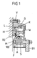
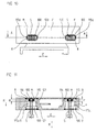
- FIG. 1 shows a cross section through a position measuring device in the form of a length measuring system, which is used to determine the relative position of two along a longitudinal direction of each other movable assemblies B1, B2 of a machine tool, eg the machine bed and a tool assembly.
- the length measuring system comprises a linear scale L arranged in a cavity H of a housing G extended in the longitudinal direction E of the scale L, and a scanning unit formed by a scanning head K arranged on a scanning carriage W for scanning a measuring graduation applied on the scale L.
- the measuring graduation is arranged displaceably in the cavity H of the housing G with respect to the linear scale L along its extension direction E and is connected to a mounting foot F.
- the mounting foot F on the one hand and the housing G on the other hand are respectively connected via suitable connecting means M, S and V with the associated assembly B1 or B2 of the machine tool.
- the fastening means provided on the mounting foot F and serving for its connection to an assembly B1 of the machine tool comprise a screw S, each having a passage opening in the mounting foot F on the one hand and the corresponding assembly B1 of the machine tool engages on the other hand, as well as a nut M, in whose internal thread the screw S engages with its external thread A and which is mounted in a recess 100 of the mounting foot F.
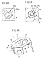
- FIGS. 2a and 2b the recess 100 of the mounting foot F serving for receiving the nut M is shown enlarged in both a perspective front view and in a rear perspective view, in FIG. 2a together with the nut M arranged therein and the associated screw S.
- the inner contour 111 of the recess 100 in cross-section polygonal, namely hexagonal, is designed and forms a circumferential inner wall 116, which opens into a bottom surface 115 of the recess 100.
- the recess 100 forms an opening through which the nut M can be inserted into the recess 100.
- the polygonal inner contour 111 of the recess 100 is adapted to the also polygonal (hexagonal) outer contour of the nut M, that they can rotate only limited in the recess 100, so that the nut M when screwing the associated screw S in the internal thread of Nut M can be held substantially rotationally fixed in the recess 100 of the mounting foot F.
- the recess 100 points in the extension direction E of the measuring arrangement, that is to say in particular the linear scale L and the housing G, cf. Fig. 1 , a greater or equal extent than the nut M, so that the nut M is still displaceable along this direction E to compensate for tolerances during assembly.
- FIG. 3a shows a first embodiment of an insertable into the recess 100 of the mounting foot F blocking element in the form of a clamp 1, with the nut M against axial slipping out of the recess 100 of the mounting foot F is securable, at the same time the mobility of the nut M perpendicular to the axial direction, ie along the extension direction E of the position measuring system, is not affected.
- the clip 1 which may preferably be formed as a stamped part of spring plate, has a base body 10, which has a to the inner contour 111 of the recess 100 adapted outer contour 11 and is provided with a slot 15 which after insertion of the Clamp 1 extends into the recess 100 along the extension direction E of the position measuring system, cf. FIGS. 3b and 3c ,
- each section 16 is angled in the form of resilient legs, which extend in the inserted state of the clip 1 substantially along each of an opposite portion of the inner wall 116 of the recess 100.
- a tab 17 is formed by cutting, which under bias from the respective leg 16 slightly outward (in the inserted state in the direction of the inner wall 116 of the recess 100, see. Figure 3c ) protrudes, and at its upper, each at the associated portion of the inner wall 116 abutting end sharp-edged (with a sharp-edged portion 18) is formed.
- the sharp-edged portions 18 of the tabs 17 are pressed under bias against the respective opposite portion of the inner wall 116 of the recess 100; and they dig into the respective portion of the inner wall 116 when an axial force against the joining direction R is exerted on the clamp 1, for example because the nut M presses against the base body 10 of the clamp 1 during assembly.
- the sharp-edged portions 18 of the tabs 17 on the inner wall 116 of the recess 100 the clip 1 is held securely in the recess 100 in the axial direction.
- the thickness d of the nut M is smaller than the distance a serving as a stop surface body 10 of the clip 1 of the bottom surface 115 of the recess 100.
- the nut M - at least before tightening the screw S - with axial play stored in the recess 100 so that it can be moved for purposes of tolerance compensation along the extension direction E of the position measuring system (ie perpendicular to the axial extent of the screw S).
- Such a displacement movement can be easily understood by the screw S, since it passes through an elongated hole 115a, which extends in the bottom surface 115 of the recess 100 and extends along that extension direction E.
- bracket 1 has the advantage that it can be used as a self-holding plug in common recesses 100 of a mounting foot F without the wall formed by the bottom surface 115 and the inner wall 116 of the recess 100 would have to be designed specifically for fixing the bracket 1.
- the fixation of the clip 1 in the recess 100 is rather achieved solely by the design of the clip 1 with corresponding sharp-edged portions 118, which can dig into the circumferential inner wall 116 of the recess 100. Due to the elastic design of the angled limbs 116 and the tabs 117, larger tolerances with respect to the outer dimensions of the clamp 1 on the one hand and the internal dimensions of the recess 100 on the other hand can be compensated hereby. Furthermore, the mobility of the nut M for purposes of tolerance compensation is virtually unaffected compared to an assembly without a clamp.
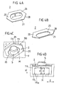
- FIG. 4a shows a second embodiment of a preferably consisting of spring plate bracket 2, which consists of a base body 20 with a polygonal (hexagonal) outer contour 21, which is provided on the one hand with a slot 25 and the other along the outer contour 21 with sharp sections 28. Due to their elastic training, the bracket 2 can be buckled readily by bending under the action of corresponding bending forces, cf.
- FIG. 4b shows a second embodiment of a preferably consisting of spring plate bracket 2, which consists of a base body 20 with a polygonal (hexagonal) outer contour 21, which is provided on the one hand with a slot 25 and the other along the outer contour 21 with sharp sections 28. Due to their elastic training, the bracket 2 can be buckled readily by bending under the action of corresponding bending forces, cf.
- FIG. 4b shows a second embodiment of a preferably consisting of spring plate bracket 2, which consists of a base body 20 with a polygonal (hexagonal) outer contour 21,
- the clamp 2 is designed such that it has a somewhat greater extent along a direction, preferably along the extension direction E of the position measuring system, than the recess 100, cf. Figures 4c and 4d.
- edge forces act on the outer contour 21 of the base body 20, which counteract insertion of the clip 2 into the recess.
- the base body 20 bulges out by bending, as in FIGS Figures 4c and 4d shown, wherein the effective length of the base body 20 of the bracket 2 is slightly reduced along the extension direction E, so that the clip 2 can be pushed further into the recess 1.
- the clamp 1 is then in the curved state with the sharp-edged portions 28 of its outer contour 21 on the inner wall 116 of the recess 100, so that it is axially fixed in the recess 100.
- the distance a between the base body 20 of the bracket 2 and the bottom surface 115 of the recess 100 is greater than the thickness d of the nut M, so that the nut M with sufficient axial clearance between the bottom surface 115 of the recess 100 and the Base 20 of the bracket 2 is mounted to allow a tolerance compensation along a direction E perpendicular to the axial.
- bracket 2 The basis of the FIGS. 4a to 4b described bracket 2 is characterized in comparison with in the FIGS. 3a to 3c shown bracket in particular by the simpler structure. However, it must be adapted more precisely to the inner contour 111 of the recess 100 with regard to its external dimensions, that is to say the design of the outer contour 21, since the possibilities associated with the use of angled resilient limbs account for the compensation of larger tolerances of said dimensions.
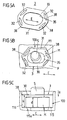
- FIGS. 5a to 5c is another consisting of spring plate bracket 3 is shown, which - like the in the FIGS. 4a to 4d shown bracket 2 - extends substantially with a base body 30 in a plane and along a direction, in particular the extension direction E of the position measuring system, a slightly larger extension than the recess 100 of the mounting foot F.
- the bracket 3 has in its main body 30 in addition to the slotted by the screw S slot 35 four weakening areas 32 in the form of elongated through holes, each extending along a sharp-edged portion 38 of the outer contour 31 of the body 30. This allows a deformation of the base body 30 in his Extension plane when pressed into the recess 100, wherein the sharp-edged portions 38 are pressed slightly into the weakened areas 32 inside, so that the clip 3 can be pressed into the recess 100 under elastic deformation of its base body 30. After inserting the clip 3 into the recess 100 press the sharp-edged portions 38 outwardly against the inner wall 116 of the recess 100, so that the clip 3 is fixed in the recess 100.
- FIGS. 5a to 5c illustrated embodiment in particular with regard to the function of the bracket 3, with the already with reference to the FIGS. 3a to 3c and 4a to 4d, so that reference is made to the relevant explanations for further details.
- the in the FIGS. 5a to 5c illustrated bracket with the in the FIGS. 4a to 4d shown since it is also a simple and inexpensive producible, flat sheet metal part, in which to pay attention to the adaptation of the outer contour 31 of the clip 1 to the inner contour 111 of the recess 100.
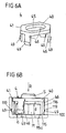
- FIG. 6a and 6b an embodiment of a clip 4 is shown, which has one of a polygonal (hexagonal) contour 41 enclosed base body 40 with a slot 45 from which four latching projections 49 provided with detent hooks 46 (substantially perpendicular) protrude.
- the latching projections 49 of the latching hook 46 are associated with corresponding undercuts 119 in the circumferential inner wall 116 of the recess 100 of the mounting base, so that the clip 4 by a latching connection to the wall 115, 116 of the recess 100, in particular on the inner wall 116, can be fixed.
- the insertion of the clip 4 in the recess 100 is made possible by a resilient design of the latching hooks 46, which can bend away during insertion of the clip 4 in the recess 100 inwardly and then engage with their latching portions 49 in the undercuts 119 of the inner wall 116.
- the in the Figures 6a and 6b shown clip may advantageously be formed as a plastic part, since no sharp-edged portions of the outer contour 41 are required to produce the locking connection with the inner wall 116 of the recess 100, which takes place by snapping the locking projections 49 in the associated undercuts 119.
- the clip 4 can be inexpensively produced by injection molding (as an injection molded part), which at the same time greater tolerances with respect to the outer dimensions of the clip 4 on the one hand and the internal dimensions of the recess 100 are compensated by the elastic design of the latching hook 46.
- a clip 4 provided with latching hooks 4 requires that corresponding latching openings, in particular in the form of undercuts 119, be produced in the recess 100 of the mounting base. This is easily possible, in particular, when the mounting foot is produced by milling, wherein corresponding detent openings can be easily produced.
- the space requirement of the latching hooks 46 can lead to a certain reduction of the extent of the tolerance compensation, which is possible along the extension direction E of the position measuring system by moving the nut M, while in the in the FIGS. 4a to 4d and 5a to 5c, planar brackets 2, 3 tolerance compensation is not affected at all.
- bracket 5 which in turn may be a cost-effectively made of plastic injection molded part.
- This comprises a flat base body 50 delimited by a polygonal (hexagonal) outer contour 51 with a slot 55 from which two pins 53, which are provided with ribs 54, protrude perpendicularly.
- the pin 53 corresponding holes 113 are associated in the form of holes in the vicinity of the recess 100, in which the pins 53 can be inserted, the ribs 54 press against the outer walls of the holes 113 and so for a reliable fixation the clip 5 by engagement of the pins 53 in the associated bores 113 provide.
- FIGS. 7a and 7b shown Compared to the basis of the Figures 6a and 6b shown, also produced as an injection molded part 4 is characterized in the FIGS. 7a and 7b shown, by a plug connection to the recess 100 festlegbare bracket 5 mainly characterized in that the extent of tolerance compensation by displacement of the nut M in the recess 100 along a direction of extension E of the position measuring system is not affected. However, here an additional processing of the material in the vicinity of the recess 100 is required by 53 suitable holes 113 are produced there for receiving the pin.
- FIGS. 8 and 9 show two embodiments in which the nut M is secured by circumferentially clamping in the recess 100 against axial falling out of the recess 100. It is particularly advantageous if the blocking element 6, 7 is arranged between the nut M and the inner wall 116 of the recess 100 and consists of elastically yielding material, for example plastic.
- the blocking element is an elastically yielding coating 7 applied to the outer circumference of the nut M.
- This coating can be created, for example, by vulcanization.
- An elastic intermediate layer 6, 7 between the nut M and the inner wall 116 of the recess 100 has the advantage that manufacturing tolerances are compensated by nut M and recess 100 and still the nut M in the recess 100 is securely clamped radially. In addition, a simple insertion and removal of the nut M from the recess 100 is ensured. Another advantage is that the nut M when screwing the screw S in the recess 100 of the position of the screw S can be adapted by the mother M can be moved perpendicular to the axial direction of the associated screw S. The possible path of movement depends on the thickness and the elasticity of the coating 7 or of the O-ring 6 and is selected according to the requirements.
- the elastic coating 7 can alternatively also be arranged on the inner wall 116 of the recess 100.
- the O-ring 6 may alternatively be incorporated in a groove of the inner wall 116 of the recess 100.
- FIGS. 10 and 11 show a particularly advantageous embodiment.
- a locking element in the form of an at least in the radial direction (direction perpendicular to R) expandable element 8 is arranged.
- this element is an elastically yielding O-ring 8 in a groove 121 of the recess 100.
- the distance a between the bottom 115 of the recess 100 and the O-ring 8 is greater in the axial direction R or at least equal to the thickness of the nut M. This has the advantage that the nut M can be moved in the inserted into the recess 100 state in the direction E in the elongated recess 100.
- the O-ring 8 thus limits the access opening of the recess 100 circumferentially such that it exerts a surmountable resistance when pressing the nut M on this.
- the indentation force of the nut M leads to a radial widening of the O-ring 8 and a release of the access opening of the recess 100 for the nut M. If the nut M is fully pressed into the recess 100, the O-ring 8 relaxes behind the nut M again and releases mother M on a circumference. By the relaxation of the O-ring 8 closes the access opening and forms a barrier to the movement of the nut M in the axial direction R.
- FIGS. 8 to 11 The in the FIGS. 8 to 11 The examples shown have the advantage that the blocking element 6, 7, 8 is designed and arranged such that it can already be mounted on the recess 100 or on the nut M when the nut M is inserted into the recess 100.
- the manufacturer of the position-measuring device can thereby provide a ready-to-install device without the user requiring additional work steps during assembly.
Landscapes
- Physics & Mathematics (AREA)
- General Physics & Mathematics (AREA)
- Clamps And Clips (AREA)
- Length Measuring Devices With Unspecified Measuring Means (AREA)
- Connection Of Plates (AREA)
- A Measuring Device Byusing Mechanical Method (AREA)
Applications Claiming Priority (3)
| Application Number | Priority Date | Filing Date | Title |
|---|---|---|---|
| DE102004025192 | 2004-05-18 | ||
| DE102005013364A DE102005013364A1 (de) | 2004-05-18 | 2005-03-23 | Positionsmesseinrichtung |
| PCT/EP2005/003586 WO2005116461A1 (de) | 2004-05-18 | 2005-04-06 | Positionsmesseinrichtung |
Publications (2)
| Publication Number | Publication Date |
|---|---|
| EP1751437A1 EP1751437A1 (de) | 2007-02-14 |
| EP1751437B1 true EP1751437B1 (de) | 2012-02-22 |
Family
ID=34964460
Family Applications (1)
| Application Number | Title | Priority Date | Filing Date |
|---|---|---|---|
| EP05731899A Expired - Lifetime EP1751437B1 (de) | 2004-05-18 | 2005-04-06 | Positionsmesseinrichtung |
Country Status (7)
| Country | Link |
|---|---|
| US (1) | US7284338B2 (enExample) |
| EP (1) | EP1751437B1 (enExample) |
| JP (1) | JP4722918B2 (enExample) |
| AT (1) | ATE546657T1 (enExample) |
| DE (1) | DE102005013364A1 (enExample) |
| ES (1) | ES2380104T3 (enExample) |
| WO (1) | WO2005116461A1 (enExample) |
Families Citing this family (7)
| Publication number | Priority date | Publication date | Assignee | Title |
|---|---|---|---|---|
| JP2010236639A (ja) * | 2009-03-31 | 2010-10-21 | Nippon Steel & Sumikin Metal Products Co Ltd | ナット保持部材およびこれを用いた管状部材のボルト接合構造 |
| DE102011079464A1 (de) * | 2011-07-20 | 2013-01-24 | Dr. Johannes Heidenhain Gmbh | Längenmesseinrichtung |
| ES2618855T3 (es) * | 2014-10-14 | 2017-06-22 | Dr. Johannes Heidenhain Gmbh | Dispositivo de medición de posición con dispositivo para la compensación de errores por dilatación térmica de una regla graduada |
| DE102015114192A1 (de) * | 2015-08-26 | 2017-03-02 | Ebm-Papst Mulfingen Gmbh & Co. Kg | Verbindungssystem zur Steckerpositionierung |
| JP6909567B2 (ja) * | 2016-09-26 | 2021-07-28 | 株式会社ミツトヨ | 直線変位測定装置の取付け具 |
| DE102018109256A1 (de) * | 2018-04-18 | 2019-10-24 | Kuka Deutschland Gmbh | Abdeckungselement für Gehäuseabschnitt eines Manipulators |
| DE102021200417B3 (de) * | 2021-01-18 | 2022-04-28 | Dr. Johannes Heidenhain Gmbh | Längenmesseinrichtung |
Family Cites Families (10)
| Publication number | Priority date | Publication date | Assignee | Title |
|---|---|---|---|---|
| GB780237A (en) | 1954-08-04 | 1957-07-31 | Waldes Kohinoor Inc | Improvements in or relating to self-locking retaining rings |
| US3053357A (en) * | 1958-12-31 | 1962-09-11 | Gen Electric | Captive nut with bolt guiding means |
| US5137406A (en) * | 1991-08-07 | 1992-08-11 | Vsi Corporation | Shear-transfer fastener assembly |
| JPH066728U (ja) * | 1992-06-30 | 1994-01-28 | ぺんてる株式会社 | ナット保持孔 |
| JPH09287607A (ja) * | 1996-04-22 | 1997-11-04 | Thk Kk | ボルト及びボルトを組み込んだ直線運動案内装置の軌道レール |
| DE19645605A1 (de) * | 1996-11-06 | 1998-05-07 | Heidenhain Gmbh Dr Johannes | Positionsmeßeinrichtung und Verfahren zur Montage eines Abtastelementes einer Positionsmeßeinrichtung |
| DE19918654B4 (de) * | 1999-04-16 | 2004-07-15 | Dr. Johannes Heidenhain Gmbh | Sicherungsvorrichtung für den Transport und die Montage einer Meßeinrichtung |
| JP2002147426A (ja) * | 2000-11-07 | 2002-05-22 | Nakai Kogyo Kk | ナット保持構造及びボルト保持構造 |
| DE10347965A1 (de) * | 2003-10-10 | 2005-05-04 | Heidenhain Gmbh Dr Johannes | Sicherungsvorrichtung für den Transport und die Montage einer Messeinrichtung |
| DE102006020067A1 (de) * | 2005-06-11 | 2006-12-14 | Dr. Johannes Heidenhain Gmbh | Kupplung und Winkelmesseinrichtung mit dieser Kupplung |
-
2005
- 2005-03-23 DE DE102005013364A patent/DE102005013364A1/de not_active Withdrawn
- 2005-04-06 US US10/565,708 patent/US7284338B2/en not_active Expired - Lifetime
- 2005-04-06 ES ES05731899T patent/ES2380104T3/es not_active Expired - Lifetime
- 2005-04-06 AT AT05731899T patent/ATE546657T1/de active
- 2005-04-06 WO PCT/EP2005/003586 patent/WO2005116461A1/de not_active Ceased
- 2005-04-06 JP JP2007516995A patent/JP4722918B2/ja not_active Expired - Fee Related
- 2005-04-06 EP EP05731899A patent/EP1751437B1/de not_active Expired - Lifetime
Also Published As
| Publication number | Publication date |
|---|---|
| JP2007538237A (ja) | 2007-12-27 |
| DE102005013364A1 (de) | 2005-12-15 |
| US7284338B2 (en) | 2007-10-23 |
| ATE546657T1 (de) | 2012-03-15 |
| EP1751437A1 (de) | 2007-02-14 |
| US20070079519A1 (en) | 2007-04-12 |
| ES2380104T3 (es) | 2012-05-08 |
| JP4722918B2 (ja) | 2011-07-13 |
| WO2005116461A1 (de) | 2005-12-08 |
Similar Documents
| Publication | Publication Date | Title |
|---|---|---|
| EP2015079B1 (de) | Halteteil zur Montage eines Sensors | |
| DE10159380B4 (de) | Verbindungsmutter zum Anschrauben von Konstruktionselementen an einem plattenartigen Bauteil | |
| EP0353395B1 (de) | Winkelmessvorrichtung | |
| DE60304318T2 (de) | Befestigung einer rohrklemme | |
| DE202008006958U1 (de) | Verbindungsbaugruppe zur Befestigung eines Anbauelements auf einem Träger | |
| EP3497339B1 (de) | Federvorrichtung und verbindungsvorrichtung | |
| DE10354117B4 (de) | Toleranzausgleichselement | |
| DE102010024870A1 (de) | Vorrichtung zum Befestigen eines Bauteils an einem Befestigungsbolzen | |
| DE3214528C2 (de) | Vorrichtung zur Festlegung von Instrumentengehäusen in einer Trägerplatte | |
| EP1751437B1 (de) | Positionsmesseinrichtung | |
| DE102004001788A1 (de) | Anordnung zur axial verstellbaren Halterung eines berührungslos arbeitenden Sensors | |
| EP2128366B1 (de) | Beschlagelement für eine Schiebetür | |
| EP1522826B1 (de) | Sicherungsvorrichtung für den Transport und die Montage einer Messeinrichtung | |
| DE102010048956A1 (de) | Vorrichtung und Verfahren zur Befestigung eines mindestens eine Öffnung aufweisenden Bauteils an einem Trägerteil | |
| DE102020133147A1 (de) | Dachreling für ein Kraftfahrzeug, Kraftfahrzeug sowie Verfahren zum Montieren einer Dachreling an einem Dach eines Kraftfahrzeugs | |
| EP4110140B1 (de) | Stellvorrichtung für möbel und verfahren zur montage einer stellvorrichtung | |
| DE102004042906A1 (de) | Vorrichtung zum Verbinden eines Bauteils einer Verstelleinrichtung eines Kraftfahrzeugs mit einer Befestigungsplatte | |
| DE10138161C1 (de) | Befestigungsvorrichtung für ein zylindrisches Gerät | |
| DE29812988U1 (de) | Fixiervorrichtung für nebeneinander angeordnete Knochen und Anlegeinstrument dafür | |
| DE19828233A1 (de) | Wandkonsole | |
| DE102006022890A1 (de) | Befestigungssystem mit einem Clip | |
| WO2020244982A1 (de) | Gurtaufrollervorrichtung für ein kraftfahrzeug | |
| DE69802596T2 (de) | Lösbare Befestigungsvorrichtung insbesondere für ein Karosseriebauteil | |
| DE202007016892U1 (de) | Verbindungssystem für rinnenförmige Profilstäbe und Verbindungsanordnung | |
| DE102021133272A1 (de) | Verbindungsanordnung und Profilverbindungsanordnung |
Legal Events
| Date | Code | Title | Description |
|---|---|---|---|
| PUAI | Public reference made under article 153(3) epc to a published international application that has entered the european phase |
Free format text: ORIGINAL CODE: 0009012 |
|
| 17P | Request for examination filed |
Effective date: 20061218 |
|
| AK | Designated contracting states |
Kind code of ref document: A1 Designated state(s): AT BE BG CH CY CZ DE DK EE ES FI FR GB GR HU IE IS IT LI LT LU MC NL PL PT RO SE SI SK TR |
|
| RIN1 | Information on inventor provided before grant (corrected) |
Inventor name: TAUBER, JOHANN Inventor name: HAGER, ANDREAS Inventor name: FIEDLER, KARL |
|
| DAX | Request for extension of the european patent (deleted) | ||
| 17Q | First examination report despatched |
Effective date: 20081127 |
|
| GRAP | Despatch of communication of intention to grant a patent |
Free format text: ORIGINAL CODE: EPIDOSNIGR1 |
|
| GRAS | Grant fee paid |
Free format text: ORIGINAL CODE: EPIDOSNIGR3 |
|
| GRAA | (expected) grant |
Free format text: ORIGINAL CODE: 0009210 |
|
| AK | Designated contracting states |
Kind code of ref document: B1 Designated state(s): AT BE BG CH CY CZ DE DK EE ES FI FR GB GR HU IE IS IT LI LT LU MC NL PL PT RO SE SI SK TR |
|
| REG | Reference to a national code |
Ref country code: GB Ref legal event code: FG4D Free format text: NOT ENGLISH |
|
| REG | Reference to a national code |
Ref country code: CH Ref legal event code: NV Representative=s name: ICB INGENIEURS CONSEILS EN BREVETS SA Ref country code: CH Ref legal event code: EP |
|
| REG | Reference to a national code |
Ref country code: AT Ref legal event code: REF Ref document number: 546657 Country of ref document: AT Kind code of ref document: T Effective date: 20120315 |
|
| REG | Reference to a national code |
Ref country code: IE Ref legal event code: FG4D Free format text: LANGUAGE OF EP DOCUMENT: GERMAN |
|
| REG | Reference to a national code |
Ref country code: DE Ref legal event code: R096 Ref document number: 502005012465 Country of ref document: DE Effective date: 20120419 |
|
| REG | Reference to a national code |
Ref country code: ES Ref legal event code: FG2A Ref document number: 2380104 Country of ref document: ES Kind code of ref document: T3 Effective date: 20120508 |
|
| REG | Reference to a national code |
Ref country code: NL Ref legal event code: VDEP Effective date: 20120222 |
|
| LTIE | Lt: invalidation of european patent or patent extension |
Effective date: 20120222 |
|
| PG25 | Lapsed in a contracting state [announced via postgrant information from national office to epo] |
Ref country code: LT Free format text: LAPSE BECAUSE OF FAILURE TO SUBMIT A TRANSLATION OF THE DESCRIPTION OR TO PAY THE FEE WITHIN THE PRESCRIBED TIME-LIMIT Effective date: 20120222 Ref country code: NL Free format text: LAPSE BECAUSE OF FAILURE TO SUBMIT A TRANSLATION OF THE DESCRIPTION OR TO PAY THE FEE WITHIN THE PRESCRIBED TIME-LIMIT Effective date: 20120222 Ref country code: IS Free format text: LAPSE BECAUSE OF FAILURE TO SUBMIT A TRANSLATION OF THE DESCRIPTION OR TO PAY THE FEE WITHIN THE PRESCRIBED TIME-LIMIT Effective date: 20120622 |
|
| PG25 | Lapsed in a contracting state [announced via postgrant information from national office to epo] |
Ref country code: FI Free format text: LAPSE BECAUSE OF FAILURE TO SUBMIT A TRANSLATION OF THE DESCRIPTION OR TO PAY THE FEE WITHIN THE PRESCRIBED TIME-LIMIT Effective date: 20120222 Ref country code: PT Free format text: LAPSE BECAUSE OF FAILURE TO SUBMIT A TRANSLATION OF THE DESCRIPTION OR TO PAY THE FEE WITHIN THE PRESCRIBED TIME-LIMIT Effective date: 20120622 Ref country code: GR Free format text: LAPSE BECAUSE OF FAILURE TO SUBMIT A TRANSLATION OF THE DESCRIPTION OR TO PAY THE FEE WITHIN THE PRESCRIBED TIME-LIMIT Effective date: 20120523 |
|
| REG | Reference to a national code |
Ref country code: IE Ref legal event code: FD4D |
|
| PG25 | Lapsed in a contracting state [announced via postgrant information from national office to epo] |
Ref country code: CY Free format text: LAPSE BECAUSE OF FAILURE TO SUBMIT A TRANSLATION OF THE DESCRIPTION OR TO PAY THE FEE WITHIN THE PRESCRIBED TIME-LIMIT Effective date: 20120222 |
|
| BERE | Be: lapsed |
Owner name: DR. JOHANNES HEIDENHAIN G.M.B.H. Effective date: 20120430 |
|
| PG25 | Lapsed in a contracting state [announced via postgrant information from national office to epo] |
Ref country code: SI Free format text: LAPSE BECAUSE OF FAILURE TO SUBMIT A TRANSLATION OF THE DESCRIPTION OR TO PAY THE FEE WITHIN THE PRESCRIBED TIME-LIMIT Effective date: 20120222 Ref country code: DK Free format text: LAPSE BECAUSE OF FAILURE TO SUBMIT A TRANSLATION OF THE DESCRIPTION OR TO PAY THE FEE WITHIN THE PRESCRIBED TIME-LIMIT Effective date: 20120222 Ref country code: PL Free format text: LAPSE BECAUSE OF FAILURE TO SUBMIT A TRANSLATION OF THE DESCRIPTION OR TO PAY THE FEE WITHIN THE PRESCRIBED TIME-LIMIT Effective date: 20120222 Ref country code: RO Free format text: LAPSE BECAUSE OF FAILURE TO SUBMIT A TRANSLATION OF THE DESCRIPTION OR TO PAY THE FEE WITHIN THE PRESCRIBED TIME-LIMIT Effective date: 20120222 Ref country code: CZ Free format text: LAPSE BECAUSE OF FAILURE TO SUBMIT A TRANSLATION OF THE DESCRIPTION OR TO PAY THE FEE WITHIN THE PRESCRIBED TIME-LIMIT Effective date: 20120222 Ref country code: SE Free format text: LAPSE BECAUSE OF FAILURE TO SUBMIT A TRANSLATION OF THE DESCRIPTION OR TO PAY THE FEE WITHIN THE PRESCRIBED TIME-LIMIT Effective date: 20120222 Ref country code: IE Free format text: LAPSE BECAUSE OF FAILURE TO SUBMIT A TRANSLATION OF THE DESCRIPTION OR TO PAY THE FEE WITHIN THE PRESCRIBED TIME-LIMIT Effective date: 20120222 Ref country code: EE Free format text: LAPSE BECAUSE OF FAILURE TO SUBMIT A TRANSLATION OF THE DESCRIPTION OR TO PAY THE FEE WITHIN THE PRESCRIBED TIME-LIMIT Effective date: 20120222 |
|
| PG25 | Lapsed in a contracting state [announced via postgrant information from national office to epo] |
Ref country code: MC Free format text: LAPSE BECAUSE OF NON-PAYMENT OF DUE FEES Effective date: 20120430 Ref country code: SK Free format text: LAPSE BECAUSE OF FAILURE TO SUBMIT A TRANSLATION OF THE DESCRIPTION OR TO PAY THE FEE WITHIN THE PRESCRIBED TIME-LIMIT Effective date: 20120222 Ref country code: IT Free format text: LAPSE BECAUSE OF FAILURE TO SUBMIT A TRANSLATION OF THE DESCRIPTION OR TO PAY THE FEE WITHIN THE PRESCRIBED TIME-LIMIT Effective date: 20120222 |
|
| PLBE | No opposition filed within time limit |
Free format text: ORIGINAL CODE: 0009261 |
|
| STAA | Information on the status of an ep patent application or granted ep patent |
Free format text: STATUS: NO OPPOSITION FILED WITHIN TIME LIMIT |
|
| REG | Reference to a national code |
Ref country code: FR Ref legal event code: ST Effective date: 20121228 |
|
| 26N | No opposition filed |
Effective date: 20121123 |
|
| PG25 | Lapsed in a contracting state [announced via postgrant information from national office to epo] |
Ref country code: BE Free format text: LAPSE BECAUSE OF NON-PAYMENT OF DUE FEES Effective date: 20120430 |
|
| PG25 | Lapsed in a contracting state [announced via postgrant information from national office to epo] |
Ref country code: FR Free format text: LAPSE BECAUSE OF NON-PAYMENT OF DUE FEES Effective date: 20120430 |
|
| REG | Reference to a national code |
Ref country code: DE Ref legal event code: R097 Ref document number: 502005012465 Country of ref document: DE Effective date: 20121123 |
|
| PG25 | Lapsed in a contracting state [announced via postgrant information from national office to epo] |
Ref country code: BG Free format text: LAPSE BECAUSE OF FAILURE TO SUBMIT A TRANSLATION OF THE DESCRIPTION OR TO PAY THE FEE WITHIN THE PRESCRIBED TIME-LIMIT Effective date: 20120522 |
|
| PG25 | Lapsed in a contracting state [announced via postgrant information from national office to epo] |
Ref country code: TR Free format text: LAPSE BECAUSE OF FAILURE TO SUBMIT A TRANSLATION OF THE DESCRIPTION OR TO PAY THE FEE WITHIN THE PRESCRIBED TIME-LIMIT Effective date: 20120222 |
|
| PG25 | Lapsed in a contracting state [announced via postgrant information from national office to epo] |
Ref country code: LU Free format text: LAPSE BECAUSE OF NON-PAYMENT OF DUE FEES Effective date: 20120406 |
|
| PG25 | Lapsed in a contracting state [announced via postgrant information from national office to epo] |
Ref country code: HU Free format text: LAPSE BECAUSE OF FAILURE TO SUBMIT A TRANSLATION OF THE DESCRIPTION OR TO PAY THE FEE WITHIN THE PRESCRIBED TIME-LIMIT Effective date: 20050406 |
|
| PGFP | Annual fee paid to national office [announced via postgrant information from national office to epo] |
Ref country code: AT Payment date: 20150421 Year of fee payment: 11 |
|
| REG | Reference to a national code |
Ref country code: AT Ref legal event code: MM01 Ref document number: 546657 Country of ref document: AT Kind code of ref document: T Effective date: 20160406 |
|
| PG25 | Lapsed in a contracting state [announced via postgrant information from national office to epo] |
Ref country code: AT Free format text: LAPSE BECAUSE OF NON-PAYMENT OF DUE FEES Effective date: 20160406 |
|
| PGFP | Annual fee paid to national office [announced via postgrant information from national office to epo] |
Ref country code: ES Payment date: 20200629 Year of fee payment: 16 Ref country code: CH Payment date: 20200420 Year of fee payment: 16 |
|
| PGFP | Annual fee paid to national office [announced via postgrant information from national office to epo] |
Ref country code: GB Payment date: 20200427 Year of fee payment: 16 |
|
| GBPC | Gb: european patent ceased through non-payment of renewal fee |
Effective date: 20210406 |
|
| PG25 | Lapsed in a contracting state [announced via postgrant information from national office to epo] |
Ref country code: CH Free format text: LAPSE BECAUSE OF NON-PAYMENT OF DUE FEES Effective date: 20210430 Ref country code: LI Free format text: LAPSE BECAUSE OF NON-PAYMENT OF DUE FEES Effective date: 20210430 Ref country code: GB Free format text: LAPSE BECAUSE OF NON-PAYMENT OF DUE FEES Effective date: 20210406 |
|
| REG | Reference to a national code |
Ref country code: ES Ref legal event code: FD2A Effective date: 20220630 |
|
| PG25 | Lapsed in a contracting state [announced via postgrant information from national office to epo] |
Ref country code: ES Free format text: LAPSE BECAUSE OF NON-PAYMENT OF DUE FEES Effective date: 20210407 |
|
| PGFP | Annual fee paid to national office [announced via postgrant information from national office to epo] |
Ref country code: DE Payment date: 20220620 Year of fee payment: 19 |
|
| REG | Reference to a national code |
Ref country code: DE Ref legal event code: R119 Ref document number: 502005012465 Country of ref document: DE |
|
| PG25 | Lapsed in a contracting state [announced via postgrant information from national office to epo] |
Ref country code: DE Free format text: LAPSE BECAUSE OF NON-PAYMENT OF DUE FEES Effective date: 20241105 |
|
| PG25 | Lapsed in a contracting state [announced via postgrant information from national office to epo] |
Ref country code: DE Free format text: LAPSE BECAUSE OF NON-PAYMENT OF DUE FEES Effective date: 20241105 |