EP1750960B1 - Toit de vehicule - Google Patents
Toit de vehicule Download PDFInfo
- Publication number
- EP1750960B1 EP1750960B1 EP05743148A EP05743148A EP1750960B1 EP 1750960 B1 EP1750960 B1 EP 1750960B1 EP 05743148 A EP05743148 A EP 05743148A EP 05743148 A EP05743148 A EP 05743148A EP 1750960 B1 EP1750960 B1 EP 1750960B1
- Authority
- EP
- European Patent Office
- Prior art keywords
- pane
- foam
- vehicle roof
- foam cladding
- edge
- Prior art date
- Legal status (The legal status is an assumption and is not a legal conclusion. Google has not performed a legal analysis and makes no representation as to the accuracy of the status listed.)
- Not-in-force
Links
Images


Classifications
-
- B—PERFORMING OPERATIONS; TRANSPORTING
- B60—VEHICLES IN GENERAL
- B60J—WINDOWS, WINDSCREENS, NON-FIXED ROOFS, DOORS, OR SIMILAR DEVICES FOR VEHICLES; REMOVABLE EXTERNAL PROTECTIVE COVERINGS SPECIALLY ADAPTED FOR VEHICLES
- B60J7/00—Non-fixed roofs; Roofs with movable panels, e.g. rotary sunroofs
- B60J7/02—Non-fixed roofs; Roofs with movable panels, e.g. rotary sunroofs of sliding type, e.g. comprising guide shoes
- B60J7/04—Non-fixed roofs; Roofs with movable panels, e.g. rotary sunroofs of sliding type, e.g. comprising guide shoes with rigid plate-like element or elements, e.g. open roofs with harmonica-type folding rigid panels
- B60J7/043—Sunroofs e.g. sliding above the roof
-
- B—PERFORMING OPERATIONS; TRANSPORTING
- B60—VEHICLES IN GENERAL
- B60J—WINDOWS, WINDSCREENS, NON-FIXED ROOFS, DOORS, OR SIMILAR DEVICES FOR VEHICLES; REMOVABLE EXTERNAL PROTECTIVE COVERINGS SPECIALLY ADAPTED FOR VEHICLES
- B60J10/00—Sealing arrangements
- B60J10/80—Sealing arrangements specially adapted for opening panels, e.g. doors
- B60J10/82—Sealing arrangements specially adapted for opening panels, e.g. doors for movable panels in roofs
-
- B—PERFORMING OPERATIONS; TRANSPORTING
- B60—VEHICLES IN GENERAL
- B60J—WINDOWS, WINDSCREENS, NON-FIXED ROOFS, DOORS, OR SIMILAR DEVICES FOR VEHICLES; REMOVABLE EXTERNAL PROTECTIVE COVERINGS SPECIALLY ADAPTED FOR VEHICLES
- B60J7/00—Non-fixed roofs; Roofs with movable panels, e.g. rotary sunroofs
Definitions
- the present invention relates to a vehicle roof according to the preamble of claims 1, 3, 5 and 6 ..
- the disc is usually a glass pane which is connected by means of a peripheral frame with the vehicle roof itself or with an adjustment mechanism for adjusting the lid.
- the frame may further be formed by a foam around the disc, in which a metallic reinforcing or holding frame, for example, a cover inner plate is inserted.
- a glass lid with a light source in a DeckelrandMumung is for example from the EP 1 277 616 A1 known.
- plastic windows are also used in vehicle construction, in particular for fixed elements, which are glued to a frame surrounding the pane.
- glass sheets are advantageous in that they are easier to process, in particular using Umschaumungstechniken, it is disadvantageous that glass covers have a considerable weight, which is not only disadvantageous in view of the total weight of the Dachaufbäus, but especially if it is the lid is a movable lid, which then requires a correspondingly more complex design of the lid supporting components and the drive of the lid.
- plastic lids are lighter than glass lids, they are much harder to assemble than these. This is because, on the one hand, the plastics used to manufacture vehicle roof lids typically have coefficients of thermal expansion that are significantly different from those of the metallic reinforcing and holding frame and therefore require corresponding movable connections between the disk and the frame, as in, for example, US Pat DE 101 08 527 is explained.
- the disc is a plastic disc and the frame is formed by a foam around the disc, wherein the shape of the disc in at least a portion of the connecting portion between the disc and the Envelope is chosen so that is ensured by a positive connection for a permanent mechanical connection between the disc and the foam.
- the advantages of ease of processing glass covers can be combined with those of the lower weight of plastic roofs, which is due to the positive connection between the plastic disc and the foam for a permanent secure connection between the disc and foam provided, also due to external influences and especially from heat influences no deterioration.
- the form fit ensures a permanent and permanent mechanical connection between the plastic disc and the foam under all operating conditions of the vehicle roof.
- the positive connection between the disc and foam around results from the shape of the disc itself, are none additional manufacturing or assembly steps required to connect the disc with the foam. Rather, the shaping elements, which ensure the positive connection between the disc and the foam, formed directly during the molding of the disc in one piece. Then, if the correspondingly shaped disc is introduced into the foam-molding tool and foamed, the foam-molding material fills the corresponding shaping elements and thus ensures the positive connection between the disk and the foam coating.
- the disc at least one recess into which engages the foam.
- the disc has at least one protrusion or a projection which is embedded in the foam casing.
- the disc along at least part of its side edge on an undercut, which is engaged behind by the foam.
- the disc is encompassed along at least part of its side edge of the foam, in which case the disc in the part of its side edge, in which it is encompassed by the foam, has a reduced cross-section, so that also in Envelope area can accomplish a flush roof surface.
- the disc may have a chamfer, a countersink and / or a chamfer in the part of its side edge in which it is encompassed by the foam.
- the shape of the recess is chosen so that it is engaged behind by the foam.
- Such recesses may be provided in the edge region of the disc at the top and / or bottom and at the end face. Furthermore, this may be a series of individual recesses or else a groove running along at least one region of the side edge.
- the shape of the projection is chosen so that it is engaged behind by the foam. This can be accomplished, for example, by forming a substantially L- or T-shaped projection on the disc, which, when embedded in the foam, not only displaces the disc and the foam but also moves it away from one another. Movement of the disc and foam around it prevented.
- the disc along its side edge on a recess or groove which fills with foaming material during foaming of the disc.
- the disc may have a substantially transparent inner region and a substantially opaque edge region, so that the regions of the disc, in which the holding elements of the disc are located, are covered to the outside and results in a uniform appearance of the disc.
- the opaque edge area may be formed, for example, as a blackened area or as an area that is color-matched to the fixed roof area.
- the substantially opaque edge region is preferably integrally formed on the substantially transparent inner region.
- the disk may be formed by a substantially transparent plastic disk, to which in its edge region a layer of a substantially opaque plastic is integrally formed.
- the transparent pane can be designed so that it spans the roof opening substantially completely, wherein the layer of substantially opaque plastic is integrally formed on the underside of the transparent pane.
- the disk may be made of a substantially transparent polycarbonate material, to which in its edge region a layer of a substantially opaque, for example, black polycarbonate material is integrally formed.
- edge area of the transparent plastic pane While it would be possible in principle to color the edge area of the transparent plastic pane, for example by applying a color layer, it is preferred for reasons of stability to manufacture the pane in a two-stage production process in which the actual pane is manufactured from a transparent material in a first step then an edge region of a substantially identical but differently colored material is formed, so that a uniform component results, which is inferior in terms of its stability and further processing of a made of only one material disc in nothing.
- the disc on its outside, preferably also on its inside, with a additional hard material layer, for example of polysiloxane, be provided in order to increase the abrasion and scratch resistance of the disc.
- a hard material layer for example of polysiloxane
- the hard material layer may optionally also serve as a bonding agent between the plastic disk and the foam coating.
- a reinforcing frame such as an inner cover plate may be inserted into the foam, in which case the outer edge of the inner cover plate may be embedded in the foam, while the inner edge of the inner cover plate rests against the underside of the disc.
- a damping layer such as a rubber, sponge rubber or textile layer may be provided, for example, on the inner cover plate by means of gluing or Flocking is applied.
- attachments made of metal or plastic are to be attached to the cover, such as diaphragms, seals, antennas, cable ducts, roller blinds, drive cables or the like, they may be embedded directly in the foam enclosure.
- holders such as e.g. Threaded bushings, sleeves, retaining clips or other inserts for fixing such attachments be embedded, or it may be molded directly into the foam recesses for attachment of such attachments. If attachments or brackets for attachments are to be embedded in the foam, then they can be inserted directly into the foaming mold during foaming and thus embedded in the foam.
- the foam can be made of a polyurethane material.
- a cover 13 is provided, which in the exemplary embodiment shown is a cover 13 which can be displaced along a roof-mounted frame 15.
- the present invention is particularly applicable to roofs with fixed elements, sliding roofs, sliding roofs, spoiler roofs, exterior sunroofs and the like.
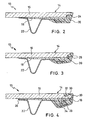
- FIG. 2 shows the lid 13 Fig.1 in the area of its side edge.
- the actual lid forming, the roof opening covering disc 14 here consists of a transparent disc 16, which is made for example of transparent polycarbonate, to the underside of a strip 18 of non-transparent material, such as black polycarbonate, is integrally formed.
- a transparent disc 16 which is made for example of transparent polycarbonate
- a strip 18 of non-transparent material such as black polycarbonate
- Such a disk can be produced by means of a two-stage shaping process, in which a layer of a substantially identical but differently colored material is then formed in a second step in a corresponding molding tool, for example, the first to form a transparent material one-piece disc made of uniform material.
- the disc 14 with a foam 20, for example a polyurethane material, foamed which surrounds preferably surrounds the entire edge region of the disc 14 circumferentially.
- a frame is provided, in which it is as in FIG. 2 can be shown to act on an inner cover plate 22, which is preferably inserted during foaming of the disc 14 in the Umbulumungstechnikmaschine.
- the cover inner panel 22 can be connected by means of the foam 20 with the disc 14, without the need for further manufacturing or assembly steps would be required.
- the positive connection between the disk 14 and the foam 20 is produced by providing a chamfer 24 on the transparent part 16 of the disk 14 along its lower side edge, so that the disk 14, after molding the opaque region 18, against the transparent disk 16 in FIG its side edge has a groove, preferably a circumferential groove, which fills during foaming of the disc 14 with foaming material.
- a groove preferably a circumferential groove
- the positive connection between the disc 14 and foam 20 creates a firm mechanical connection of the disc 14 to the foam 20, which effectively counteracts a detachment of the disc from the foam due to high mechanical or thermal stress.
- FIG. 3 shows a modified embodiment of the lid 13 according to FIG. 2 , in which case the disk 14 formed by the transparent disk 16 and the non-transparent region 18 has, along its side edge, a peripheral indentation 26 which is filled with the foaming material of the foam casing 20.
- the disc 14 formed from the transparent plastic disc 16 and the opaque plastic portion 18 formed integrally thereon has an edge portion 30 of reduced thickness.
- a recess 32 is provided in the region of reduced thickness 30 at a distance from the outer edge of the disc.
- the outer edge of the disc 14 is foamed with polyurethane material, wherein the foam 20 engages the region of reduced thickness 30 so that the top of the foam 20 is flush with the top of the disc 14.
- FIG. 4 an embodiment of the disc 14 is shown in which on the underside of a downwardly projecting projection 28 is provided, laterally protrudes a further projection 34 so that overall results in a generally L-shaped projection which is embedded in the foaming material, that he is engaged behind by the foaming material.
- the disc 14 may be designed such that the shaping features which provide a positive fit with the foam 20, in particular the recess 32 and the L-shaped projection 28, 34, are provided in partial regions of the disc or extend along the entire circumference of the disc ,
- a cover inner panel 22 In the foam 20, the outer edge of a cover inner panel 22 is further embedded, the inner edge rests against the disc 14 from below. In order to cover the lid inner panel 22 upwards, the area 18 of the pane made of an opaque plastic extends to just above the inner edge of the inner lid panel 22. Between the inner edge of the inner cover plate 22 and the disc 14, a damping member 36 may further be provided, which avoids a rattling or squeaking, which could be caused by a relative movement between the disc and inner cover sheet. This damping 36 is preferably an elastic applied to the upper side of the cover inner panel 22 Material, such as rubber, foam rubber or textile materials, for example, a flocking the top of the inner lid sheet 22nd
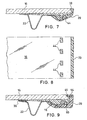
- FIG. 5 shows a further embodiment of a lid 13, wherein the outer edge of the disc 14 is encompassed by the foam 20.
- a chamfer 38 is provided along the outer edge of the disk 14 in its transparent part 16, which is filled with foam material 40 during foaming of the disk 14 becomes.
- additional attachments such as screens or roller guides, are to be attached to the cover 13, as can be seen in FIG FIG. 5 is illustrated, holders for such attachments, such as threaded bushings 52 are embedded directly into the foam 20. The threaded bushing 52 was in this case inserted during the foaming of the disc 14 in the foaming tool with, without additional assembly steps would have been required.
- FIG. 6 shows a further embodiment of the lid 13, in which the transparent disc 16 is formed as a disc having a substantially uniform thickness, but in which integrally formed on the underside portion 18 of non-transparent material has a T-shaped projection 48 which in the PU foaming material 20 is embedded. Further shows FIG. 6 an embodiment of the lid, in which in the foam casing 20 laterally a receptacle 42 is provided to secure a sealing element (not shown) to the lid.
- a receptacle 42 is provided to secure a sealing element (not shown) to the lid.
- Such recordings by means of which attachments such as seals, diaphragms, etc. can be attached to the lid can be formed at any point of the foam 20.
- FIGS. 7 and 8 an embodiment of the lid 13 is shown, in which the positive connection between the disc 14 and the foam 20 on the one hand by a along the upper outer edge of the transparent disc 16 extending chamfer 38 and accomplished by a plurality of elevations 44 which on the underside of the disc 14 in their non-transparent area are provided.
- the elevations 44 may be arranged in a row one behind the other at a uniform distance from the side edge of the disc.
- FIG. 9 Two further measures for providing a positive fit of the foam 20 and the disc 14 are in FIG. 9 shown.
- the upper side edge of the disc 14 is chamfered in the transparent region 16, wherein the disc is encompassed by the foaming material 20 in the region of the chamfer 46.
- a recess 50 is provided on the underside of the disc, whose inner cross section is greater than the opening cross section and which is filled with foaming material during foaming of the disc. It is understood that the recess 50 does not need to be arranged within the non-transparent area as in the example shown, but that the pane 14 formed by the transparent pane 16 and the non-transparent area 18 forms an integral one-piece component, can also hineineruxn in the transparent area 16.
- FIG. 9 further shows an embodiment of a lid 13, in which an attachment, here an antenna 54, is embedded directly in the foam 20. The fact that the antenna 54 is inserted during foaming of the disc 14 in a simple manner in the foaming tool, eliminating additional assembly steps.
Claims (21)
- Toit de véhicule avec une ouverture de toit (12) pratiquée dans une surface de toit solide (10) et avec un couvercle (13) pour fermer l'ouverture de toit, dans lequel le couvercle comprend une vitre au moins partiellement transparente (14) et un cadre assemblé à la vitre, qui s'étend sur au moins une partie du bord de la vitre, dans lequel la vitre (14) est une vitre de matière plastique et le cadre est formé par une mousse périphérique (20) entourant la vitre, et dans lequel le profil de la vitre, dans au moins une zone partielle de la région d'assemblage entre la vitre et la mousse périphérique, est en outre choisi de telle manière qu'il assure un assemblage mécanique durable entre la vitre et la mousse périphérique par un assemblage en complémentarité de forme, caractérisé en ce que la vitre (14) présente au moins un évidement (24, 26, 32, 50) dans lequel la mousse périphérique (20) s'engage.
- Toit de véhicule selon la revendication 1, dans lequel le profil de l'évidement (24, 26, 50) est choisi de telle manière que la mousse périphérique s'y accroche à l'arrière.
- Toit de véhicule, de préférence selon l'une quelconque des revendications précédentes, avec une ouverture de toit (12) pratiquée dans une surface de toit solide (10) et avec un couvercle (13) pour fermer l'ouverture de toit, dans lequel le couvercle comprend une vitre au moins partiellement transparente (14) et un cadre assemblé à la vitre, qui s'étend sur au moins une partie du bord de la vitre, dans lequel la vitre (14) est une vitre de matière plastique et le cadre est formé par une mousse périphérique (20) entourant la vitre, et dans lequel le profil de la vitre, dans au moins une zone partielle de la région d'assemblage entre la vitre et la mousse périphérique, est en outre choisi de telle manière qu'il assure un assemblage mécanique durable entre la vitre et la mousse périphérique par un assemblage en complémentarité de forme, caractérisé en ce que la vitre (14) présente au moins une surélévation (44) ou une saillie (28, 34, 48), qui est noyée dans la mousse périphérique (20).
- Toit de véhicule selon la revendication 3, dans lequel la vitre présente une saillie (34, 38) et le profil de la saillie est choisi de telle manière que la mousse périphérique (20) accroche celle-ci par l'arrière.
- Toit de véhicule, de préférence selon l'une quelconque des revendications précédentes, avec une ouverture de toit (12) pratiquée dans une surface de toit solide (10) et avec un couvercle (13) pour fermer l'ouverture de toit, dans lequel le couvercle comprend une vitre au moins partiellement transparente (14) et un cadre assemblé à la vitre, qui s'étend sur au moins une partie du bord de la vitre, dans lequel la vitre (14) est une vitre de matière plastique et le cadre est formé par une mousse périphérique (20) entourant la vitre, et dans lequel le profil de la vitre, dans au moins une zone partielle de la région d'assemblage entre la vitre et la mousse périphérique, est en outre choisi de telle manière qu'il assure un assemblage mécanique durable entre la vitre et la mousse périphérique par un assemblage en complémentarité de forme, caractérisé en ce que la vitre (14) présente, le long d'au moins une partie de son bord latéral, une contre-dépouille (24, 26, 50), que la mousse périphérique accroche par l'arrière.
- Toit de véhicule, de préférence selon l'une quelconque des revendications précédentes, avec une ouverture de toit (12) pratiquée dans une surface de toit solide (10) et avec un couvercle (13) pour fermer l'ouverture de toit, dans lequel le couvercle comprend une vitre au moins partiellement transparente (14) et un cadre assemblé à la vitre, qui s'étend sur au moins une partie du bord de la vitre, dans lequel la vitre (14) est une vitre de matière plastique et le cadre est formé par une mousse périphérique (20) entourant la vitre, et dans lequel le profil de la vitre, dans au moins une zone partielle de la région d'assemblage entre la vitre et la mousse périphérique, est en outre choisi de telle manière qu'il assure un assemblage mécanique durable entre la vitre et la mousse périphérique par un assemblage en complémentarité de forme, dans lequel la vitre (14) est enveloppée par la mousse périphérique (20) le long d'au moins une partie de son bord latéral, caractérisé en ce que la vitre (14) présente, dans la partie de son bord latéral dans laquelle elle est enveloppée par la mousse périphérique, une section transversale réduite (30), du fait qu'elle présente, dans la partie de son bord latéral dans laquelle elle est enveloppée par la mousse périphérique (20), un profil (38), un retrait (30) et/ou un chanfrein (46).
- Toit de véhicule selon l'une quelconque des revendications précédentes, dans lequel le profil de la vitre (14), qui assure un assemblage mécanique durable entre la vitre et la mousse périphérique (20) par complémentarité de forme, présente une géométrie s'étendant essentiellement sur toute la zone du bord latéral de la vitre.
- Toit de véhicule selon l'une quelconque des revendications précédentes, dans lequel la vitre (14) présente une zone intérieure essentiellement transparente (16) ainsi qu'une zone de bord essentiellement opaque (18).
- Toit de véhicule selon la revendication 8, dans lequel la zone de bord essentiellement opaque (18) est formée d'une seule pièce sur la zone intérieure essentiellement transparente (16).
- Toit de véhicule selon la revendication 8, dans lequel la vitre (14) est formée par une vitre en matière plastique essentiellement transparente (16), sur laquelle une couche (18) en une matière plastique essentiellement opaque est formée d'une seule pièce dans sa zone de bord.
- Toit de véhicule selon la revendication 10, dans lequel la couche (18) en une matière plastique essentiellement opaque est formée sur la face inférieure de la vitre de matière plastique (16).
- Toit de véhicule selon l'une quelconque des revendications 9 à 11, dans lequel la vitre (14) est fabriquée en un matériau de polycarbonate essentiellement transparent (16), sur lequel une couche (18) en un matériau de polycarbonate essentiellement opaque est formée d'une seule pièce dans sa zone de bord.
- Toit de véhicule selon l'une quelconque des revendications précédentes, dans lequel la vitre (14) est pourvue sur sa face extérieure, et de préférence aussi sur sa face intérieure, d'une couche supplémentaire de substance dure.
- Toit de véhicule selon l'une quelconque des revendications précédentes, dans lequel un cadre de renforcement (22) est noyé dans la mousse périphérique (20).
- Toit de véhicule selon l'une quelconque des revendications précédentes, dans lequel il est prévu une tôle intérieure de couvercle (22) comme cadre de renforcement.
- Toit de véhicule selon la revendication 15, dans lequel le bord extérieur de la tôle intérieure de couvercle (22) est noyé dans la mousse périphérique (20) et le bord intérieur de la tôle intérieure de couvercle est appliqué contre la face inférieure de la vitre (14).
- Toit de véhicule selon la revendication 16, dans lequel il est prévu une couche d'amortissement (16) entre la tôle intérieure de couvercle (22) et la vitre (14).
- Toit de véhicule selon l'une quelconque des revendications précédentes, dans lequel des éléments de montage (54) sont noyés dans la mousse périphérique (20).
- Toit de véhicule selon l'une quelconque des revendications précédentes, dans lequel des supports (52) pour la fixation d'éléments de montage sont noyés dans la mousse périphérique (20).
- Toit de véhicule selon l'une quelconque des revendications précédentes, dans lequel des logements (42) permettant la fixation d'éléments de montage sont formés dans la mousse périphérique (20).
- Toit de véhicule selon l'une quelconque des revendications précédentes, dans lequel la mousse périphérique (20) est fabriquée en un matériau de polyuréthane.
Applications Claiming Priority (2)
| Application Number | Priority Date | Filing Date | Title |
|---|---|---|---|
| DE102004025548A DE102004025548A1 (de) | 2004-05-25 | 2004-05-25 | Fahrzeugdach |
| PCT/EP2005/005439 WO2005115782A1 (fr) | 2004-05-25 | 2005-05-19 | Toit de vehicule |
Publications (3)
| Publication Number | Publication Date |
|---|---|
| EP1750960A1 EP1750960A1 (fr) | 2007-02-14 |
| EP1750960B1 true EP1750960B1 (fr) | 2009-03-04 |
| EP1750960B2 EP1750960B2 (fr) | 2015-05-27 |
Family
ID=34970626
Family Applications (1)
| Application Number | Title | Priority Date | Filing Date |
|---|---|---|---|
| EP05743148.8A Not-in-force EP1750960B2 (fr) | 2004-05-25 | 2005-05-19 | Toit de vehicule |
Country Status (5)
| Country | Link |
|---|---|
| US (1) | US7404598B2 (fr) |
| EP (1) | EP1750960B2 (fr) |
| AT (1) | ATE424322T1 (fr) |
| DE (2) | DE102004025548A1 (fr) |
| WO (1) | WO2005115782A1 (fr) |
Cited By (1)
| Publication number | Priority date | Publication date | Assignee | Title |
|---|---|---|---|---|
| DE102019109470A1 (de) * | 2019-04-10 | 2020-10-15 | Webasto SE | Deckel für ein Fahrzeugdach und Verfahren zum Herstellen eines Deckels |
Families Citing this family (21)
| Publication number | Priority date | Publication date | Assignee | Title |
|---|---|---|---|---|
| DE102006022927A1 (de) | 2006-05-15 | 2007-11-22 | Webasto Ag | Fahrzeugbauteil mit einer Versteifung |
| DE102007015709B4 (de) * | 2007-01-25 | 2009-09-03 | Webasto Ag | Fahrzeugdach |
| CA2674768A1 (fr) * | 2009-08-03 | 2011-02-03 | Prelco Inc. | Systeme de vitrage rigidifie par le collage d'extrusion |
| US8333426B2 (en) * | 2010-08-06 | 2012-12-18 | Honda Motor Co., Inc. | Rise up panoramic roof for a vehicle |
| EP2450239B1 (fr) * | 2010-11-04 | 2014-03-19 | Inalfa Roof Systems Group B.V. | Procédé pour raccorder deux objets et un panneau au moyen dudit procédé |
| JP2012201331A (ja) * | 2011-03-28 | 2012-10-22 | Aisin Seiki Co Ltd | サンルーフのパネル構造 |
| WO2012167879A2 (fr) * | 2011-06-06 | 2012-12-13 | Webasto Ag | Composant de véhicule |
| PT2790842T (pt) | 2011-12-14 | 2017-08-07 | Saint Gobain | Peça polímera para revestimento de fluxo |
| DE102013108081A1 (de) * | 2013-07-29 | 2015-01-29 | Roof Systems Germany Gmbh | Dachkonstruktion für ein Kraftfahrzeug und Kraftfahrzeug-Rohbaukarosserie |
| JP5775613B2 (ja) * | 2014-01-28 | 2015-09-09 | 八千代工業株式会社 | サンルーフ装置のパネル体およびサンルーフ装置のパネル体の製造方法 |
| US10112326B2 (en) | 2014-02-19 | 2018-10-30 | Webasto SE | Device and method for producing an edging of a flat extended panel |
| JP2017061229A (ja) * | 2015-09-24 | 2017-03-30 | アイシン精機株式会社 | 車両用サンルーフパネル |
| DE102015120408B3 (de) | 2015-11-25 | 2017-03-09 | Webasto SE | Deckel eines Fahrzeugdaches mit Einlegeteil in einem Kunststoffformabschnitt |
| DE102015121927B3 (de) * | 2015-12-16 | 2017-06-22 | Roof Systems Germany Gmbh | Fahrzeugdachglaselement |
| DE102017105268A1 (de) | 2017-03-13 | 2018-09-13 | Webasto SE | Deckel und System für ein Fahrzeugdach |
| DE102017108082A1 (de) * | 2017-04-13 | 2018-10-18 | Webasto SE | Dachscheibe eines Kraftfahrzeugs |
| DE102018000844A1 (de) * | 2018-02-02 | 2019-08-08 | Webasto SE | Dichtungsanordnung für einen Dachbereich eines Kraftfahrzeugs |
| DE102018124917B4 (de) * | 2018-08-22 | 2023-04-20 | Webasto SE | Fahrzeugdach mit Festdachelement |
| DE102019109591A1 (de) * | 2019-04-11 | 2020-10-15 | Dr. Ing. H.C. F. Porsche Aktiengesellschaft | Dachanbindungssystem und Verfahren |
| DE102019122207A1 (de) * | 2019-08-19 | 2021-02-25 | Webasto SE | Anordnung für ein Fahrzeugdach, Verfahren zum Herstellen einer Anordnung für ein Fahrzeugdach und Fahrzeugdach für ein Kraftfahrzeug |
| DE102021127670A1 (de) * | 2020-11-16 | 2022-05-19 | Webasto SE | Fahrzeug-Glasscheibe mit einem Kantenschutz |
Family Cites Families (13)
| Publication number | Priority date | Publication date | Assignee | Title |
|---|---|---|---|---|
| DE3506009A1 (de) † | 1985-02-21 | 1986-08-28 | Rockwell Golde Gmbh, 6000 Frankfurt | Starrer deckel fuer ein fahrzeugdach |
| DE4105389C1 (fr) | 1991-02-21 | 1992-06-11 | Webasto-Schade Gmbh, 8031 Oberpfaffenhofen, De | |
| JPH1177740A (ja) * | 1997-09-17 | 1999-03-23 | Toyota Autom Loom Works Ltd | 樹脂成形品とその製造方法及び成形型 |
| NL1009807C2 (nl) * | 1998-08-05 | 2000-02-08 | Inalfa Ind Bv | Paneelsamenstel voor een open-dakconstructie voor een voertuig. |
| DE29814743U1 (de) * | 1998-08-19 | 1999-12-30 | Meritor Automotive Gmbh | Durchsichtige Kunststoffscheibe für Kraftfahrzeugkarosserieverglasungen, insbesondere für Fahrzeugdächer |
| WO2001028744A1 (fr) * | 1999-10-18 | 2001-04-26 | Exatec, Llc. | Vitre d'automobile en plastique moule et procede pour former une bordure de masquage |
| DE10108572A1 (de) | 2000-03-24 | 2001-09-27 | Caterpillar Inc | Instandhaltungsverbesserung bei einem Einspritzeinheitskipphebelarm |
| DE10036630C1 (de) * | 2000-07-26 | 2002-01-24 | Webasto Vehicle Sys Int Gmbh | Verfahren zum Umschäumen des Umfangsrandbereichs eines Deckels für ein Fahzeugdach und Fahrzeugdach-Deckel |
| DE10108527A1 (de) * | 2001-02-22 | 2002-09-12 | Arvinmeritor Gmbh | Verbundbauteil für eine Fahrzeugkarosserie, insbesondere Deckel eines Kraftfahrzeug-Schiebedachs |
| DE10134641A1 (de) * | 2001-07-17 | 2003-05-22 | Arvinmeritor Gmbh | Schiebedach für ein Fahrzeug |
| DE10158957B4 (de) * | 2001-12-03 | 2005-10-27 | Webasto Ag | Deckel für eine Fahrzeug-Dachöffnung sowie Verfahren zur Herstellung eines Deckels |
| JP2003211967A (ja) * | 2002-01-21 | 2003-07-30 | Honda Motor Co Ltd | サンルーフ装置のガラスパネル |
| DE10206717B4 (de) † | 2002-02-18 | 2014-03-13 | Webasto Ag | Glasdeckel mit Splitterschutzfolie |
-
2004
- 2004-05-25 DE DE102004025548A patent/DE102004025548A1/de not_active Withdrawn
-
2005
- 2005-05-19 EP EP05743148.8A patent/EP1750960B2/fr not_active Not-in-force
- 2005-05-19 WO PCT/EP2005/005439 patent/WO2005115782A1/fr active Application Filing
- 2005-05-19 AT AT05743148T patent/ATE424322T1/de not_active IP Right Cessation
- 2005-05-19 DE DE502005006754T patent/DE502005006754D1/de active Active
- 2005-05-19 US US11/569,634 patent/US7404598B2/en not_active Expired - Fee Related
Cited By (1)
| Publication number | Priority date | Publication date | Assignee | Title |
|---|---|---|---|---|
| DE102019109470A1 (de) * | 2019-04-10 | 2020-10-15 | Webasto SE | Deckel für ein Fahrzeugdach und Verfahren zum Herstellen eines Deckels |
Also Published As
| Publication number | Publication date |
|---|---|
| DE502005006754D1 (de) | 2009-04-16 |
| WO2005115782A1 (fr) | 2005-12-08 |
| EP1750960A1 (fr) | 2007-02-14 |
| WO2005115782A8 (fr) | 2006-06-01 |
| DE102004025548A1 (de) | 2005-12-22 |
| US7404598B2 (en) | 2008-07-29 |
| EP1750960B2 (fr) | 2015-05-27 |
| US20070246973A1 (en) | 2007-10-25 |
| ATE424322T1 (de) | 2009-03-15 |
Similar Documents
| Publication | Publication Date | Title |
|---|---|---|
| EP1750960B1 (fr) | Toit de vehicule | |
| DE102016200475B3 (de) | Fahrzeugtürbaugruppe mit Einführbereichen an rahmenseitigen Führungselementen für ein flächenbündiges Scheibenkonzept und Montageverfahren | |
| EP2463133B1 (fr) | Joint d'étanchéité pour un module de vitrage | |
| DE3506009C2 (fr) | ||
| EP2352658B1 (fr) | Encadrement de vitre | |
| DE10163709B4 (de) | Modulartiges Fahrzeugdach | |
| EP0615876B1 (fr) | Panneau rigide pour toit de véhicule | |
| EP1807277A1 (fr) | Bande de matiere destinee a l'etancheite, au revetement ou au guidage | |
| DE2912625A1 (de) | Kunstharz-formleiste fuer fahrzeuge | |
| DE3905906C2 (de) | Spaltdichtung für Scheiben , insbesondere für Fahrzeugscheiben | |
| DE102011050752B4 (de) | Scheibeneinheit eines Fahrzeugfensters, insbesondere eines Seitenfensters | |
| DE3702402C2 (de) | Höhenverstellbare Seitenscheibe aus Isolierglas für Kraftfahrzeuge und Verfahren zu ihrer Herstellung | |
| DE102014010420A1 (de) | Fahrzeugdach mit einem Dachmodul | |
| DE10155170B4 (de) | Flächiges Glaselement für ein Fahrzeugdach und Verfahren zum Herstellen desselben | |
| DE102009026069A1 (de) | Säulenblende mit ortsfest zugeordneter Decklippe | |
| EP1131218A1 (fr) | Joint d'etancheite profile destine a une fenetre de cabriolet | |
| DE3822721C1 (fr) | ||
| DE10252912A1 (de) | Verfahren zum Herstellen eines Fahrzeugdaches mit einem Dachmodul | |
| DE112009001888T5 (de) | Kreuzarmmodul für Fahrzeugtür | |
| EP0918656A1 (fr) | Cadre profile pour vitre de fenetre mobile | |
| EP2799265A1 (fr) | Module de châssis de porte pour une porte de véhicule automobile conçue de façon modulaire et porte de véhicule automobile conçue de façon modulaire dotée d'un tel module de châssis de porte | |
| DE3612294C2 (fr) | ||
| EP1522445B1 (fr) | Joint d'étanchéité pour une porte de véhicule | |
| EP1808320B1 (fr) | Elément d'habillage mobile et procédé pour sa fabrication | |
| DE3248476C2 (fr) |
Legal Events
| Date | Code | Title | Description |
|---|---|---|---|
| PUAI | Public reference made under article 153(3) epc to a published international application that has entered the european phase |
Free format text: ORIGINAL CODE: 0009012 |
|
| 17P | Request for examination filed |
Effective date: 20061128 |
|
| AK | Designated contracting states |
Kind code of ref document: A1 Designated state(s): AT BE BG CH CY CZ DE DK EE ES FI FR GB GR HU IE IS IT LI LT LU MC NL PL PT RO SE SI SK TR |
|
| RIN1 | Information on inventor provided before grant (corrected) |
Inventor name: LANG, ANDREAS Inventor name: POLLAK, MARTIN Inventor name: WULF, FRIEDHELM Inventor name: HUEBNER, ROLAND Inventor name: MUTTENHAMMER, RUDOLF Inventor name: SCHWAIGHOFER, RALF |
|
| 17Q | First examination report despatched |
Effective date: 20070323 |
|
| DAX | Request for extension of the european patent (deleted) | ||
| GRAP | Despatch of communication of intention to grant a patent |
Free format text: ORIGINAL CODE: EPIDOSNIGR1 |
|
| RIN1 | Information on inventor provided before grant (corrected) |
Inventor name: LANG, ANDREAS Inventor name: WULF, FRIEDHELM Inventor name: MUTTENHAMMER, RUDOLF Inventor name: POLLAK, MARTIN Inventor name: HUEBNER, ROLAND Inventor name: SCHWAIGHOFER, RALF |
|
| GRAS | Grant fee paid |
Free format text: ORIGINAL CODE: EPIDOSNIGR3 |
|
| GRAA | (expected) grant |
Free format text: ORIGINAL CODE: 0009210 |
|
| AK | Designated contracting states |
Kind code of ref document: B1 Designated state(s): AT BE BG CH CY CZ DE DK EE ES FI FR GB GR HU IE IS IT LI LT LU MC NL PL PT RO SE SI SK TR |
|
| REG | Reference to a national code |
Ref country code: GB Ref legal event code: FG4D Free format text: NOT ENGLISH |
|
| REG | Reference to a national code |
Ref country code: CH Ref legal event code: EP |
|
| REG | Reference to a national code |
Ref country code: IE Ref legal event code: FG4D Free format text: LANGUAGE OF EP DOCUMENT: GERMAN |
|
| REF | Corresponds to: |
Ref document number: 502005006754 Country of ref document: DE Date of ref document: 20090416 Kind code of ref document: P |
|
| PG25 | Lapsed in a contracting state [announced via postgrant information from national office to epo] |
Ref country code: SI Free format text: LAPSE BECAUSE OF FAILURE TO SUBMIT A TRANSLATION OF THE DESCRIPTION OR TO PAY THE FEE WITHIN THE PRESCRIBED TIME-LIMIT Effective date: 20090304 Ref country code: LT Free format text: LAPSE BECAUSE OF FAILURE TO SUBMIT A TRANSLATION OF THE DESCRIPTION OR TO PAY THE FEE WITHIN THE PRESCRIBED TIME-LIMIT Effective date: 20090304 Ref country code: FI Free format text: LAPSE BECAUSE OF FAILURE TO SUBMIT A TRANSLATION OF THE DESCRIPTION OR TO PAY THE FEE WITHIN THE PRESCRIBED TIME-LIMIT Effective date: 20090304 |
|
| PG25 | Lapsed in a contracting state [announced via postgrant information from national office to epo] |
Ref country code: SE Free format text: LAPSE BECAUSE OF FAILURE TO SUBMIT A TRANSLATION OF THE DESCRIPTION OR TO PAY THE FEE WITHIN THE PRESCRIBED TIME-LIMIT Effective date: 20090604 Ref country code: PL Free format text: LAPSE BECAUSE OF FAILURE TO SUBMIT A TRANSLATION OF THE DESCRIPTION OR TO PAY THE FEE WITHIN THE PRESCRIBED TIME-LIMIT Effective date: 20090304 |
|
| REG | Reference to a national code |
Ref country code: IE Ref legal event code: FD4D |
|
| PG25 | Lapsed in a contracting state [announced via postgrant information from national office to epo] |
Ref country code: EE Free format text: LAPSE BECAUSE OF FAILURE TO SUBMIT A TRANSLATION OF THE DESCRIPTION OR TO PAY THE FEE WITHIN THE PRESCRIBED TIME-LIMIT Effective date: 20090304 Ref country code: IE Free format text: LAPSE BECAUSE OF FAILURE TO SUBMIT A TRANSLATION OF THE DESCRIPTION OR TO PAY THE FEE WITHIN THE PRESCRIBED TIME-LIMIT Effective date: 20090304 Ref country code: ES Free format text: LAPSE BECAUSE OF FAILURE TO SUBMIT A TRANSLATION OF THE DESCRIPTION OR TO PAY THE FEE WITHIN THE PRESCRIBED TIME-LIMIT Effective date: 20090615 Ref country code: CZ Free format text: LAPSE BECAUSE OF FAILURE TO SUBMIT A TRANSLATION OF THE DESCRIPTION OR TO PAY THE FEE WITHIN THE PRESCRIBED TIME-LIMIT Effective date: 20090304 Ref country code: PT Free format text: LAPSE BECAUSE OF FAILURE TO SUBMIT A TRANSLATION OF THE DESCRIPTION OR TO PAY THE FEE WITHIN THE PRESCRIBED TIME-LIMIT Effective date: 20090818 |
|
| BERE | Be: lapsed |
Owner name: WEBASTO A.G. Effective date: 20090531 |
|
| PG25 | Lapsed in a contracting state [announced via postgrant information from national office to epo] |
Ref country code: IS Free format text: LAPSE BECAUSE OF FAILURE TO SUBMIT A TRANSLATION OF THE DESCRIPTION OR TO PAY THE FEE WITHIN THE PRESCRIBED TIME-LIMIT Effective date: 20090704 Ref country code: RO Free format text: LAPSE BECAUSE OF FAILURE TO SUBMIT A TRANSLATION OF THE DESCRIPTION OR TO PAY THE FEE WITHIN THE PRESCRIBED TIME-LIMIT Effective date: 20090304 Ref country code: SK Free format text: LAPSE BECAUSE OF FAILURE TO SUBMIT A TRANSLATION OF THE DESCRIPTION OR TO PAY THE FEE WITHIN THE PRESCRIBED TIME-LIMIT Effective date: 20090304 |
|
| PLBI | Opposition filed |
Free format text: ORIGINAL CODE: 0009260 |
|
| PG25 | Lapsed in a contracting state [announced via postgrant information from national office to epo] |
Ref country code: MC Free format text: LAPSE BECAUSE OF NON-PAYMENT OF DUE FEES Effective date: 20090531 |
|
| REG | Reference to a national code |
Ref country code: CH Ref legal event code: PL |
|
| PLAX | Notice of opposition and request to file observation + time limit sent |
Free format text: ORIGINAL CODE: EPIDOSNOBS2 |
|
| 26 | Opposition filed |
Opponent name: ARVINMERITOR GMBH Effective date: 20091130 |
|
| PG25 | Lapsed in a contracting state [announced via postgrant information from national office to epo] |
Ref country code: LI Free format text: LAPSE BECAUSE OF NON-PAYMENT OF DUE FEES Effective date: 20090531 Ref country code: CH Free format text: LAPSE BECAUSE OF NON-PAYMENT OF DUE FEES Effective date: 20090531 Ref country code: DK Free format text: LAPSE BECAUSE OF FAILURE TO SUBMIT A TRANSLATION OF THE DESCRIPTION OR TO PAY THE FEE WITHIN THE PRESCRIBED TIME-LIMIT Effective date: 20090304 Ref country code: BG Free format text: LAPSE BECAUSE OF FAILURE TO SUBMIT A TRANSLATION OF THE DESCRIPTION OR TO PAY THE FEE WITHIN THE PRESCRIBED TIME-LIMIT Effective date: 20090604 |
|
| NLR1 | Nl: opposition has been filed with the epo |
Opponent name: ARVINMERITOR GMBH |
|
| PLBB | Reply of patent proprietor to notice(s) of opposition received |
Free format text: ORIGINAL CODE: EPIDOSNOBS3 |
|
| PG25 | Lapsed in a contracting state [announced via postgrant information from national office to epo] |
Ref country code: BE Free format text: LAPSE BECAUSE OF NON-PAYMENT OF DUE FEES Effective date: 20090531 |
|
| PG25 | Lapsed in a contracting state [announced via postgrant information from national office to epo] |
Ref country code: AT Free format text: LAPSE BECAUSE OF NON-PAYMENT OF DUE FEES Effective date: 20090519 |
|
| PG25 | Lapsed in a contracting state [announced via postgrant information from national office to epo] |
Ref country code: GR Free format text: LAPSE BECAUSE OF FAILURE TO SUBMIT A TRANSLATION OF THE DESCRIPTION OR TO PAY THE FEE WITHIN THE PRESCRIBED TIME-LIMIT Effective date: 20090605 |
|
| PG25 | Lapsed in a contracting state [announced via postgrant information from national office to epo] |
Ref country code: IT Free format text: LAPSE BECAUSE OF FAILURE TO SUBMIT A TRANSLATION OF THE DESCRIPTION OR TO PAY THE FEE WITHIN THE PRESCRIBED TIME-LIMIT Effective date: 20090304 |
|
| PG25 | Lapsed in a contracting state [announced via postgrant information from national office to epo] |
Ref country code: LU Free format text: LAPSE BECAUSE OF NON-PAYMENT OF DUE FEES Effective date: 20090519 |
|
| PG25 | Lapsed in a contracting state [announced via postgrant information from national office to epo] |
Ref country code: HU Free format text: LAPSE BECAUSE OF FAILURE TO SUBMIT A TRANSLATION OF THE DESCRIPTION OR TO PAY THE FEE WITHIN THE PRESCRIBED TIME-LIMIT Effective date: 20090905 |
|
| PG25 | Lapsed in a contracting state [announced via postgrant information from national office to epo] |
Ref country code: TR Free format text: LAPSE BECAUSE OF FAILURE TO SUBMIT A TRANSLATION OF THE DESCRIPTION OR TO PAY THE FEE WITHIN THE PRESCRIBED TIME-LIMIT Effective date: 20090304 |
|
| PG25 | Lapsed in a contracting state [announced via postgrant information from national office to epo] |
Ref country code: CY Free format text: LAPSE BECAUSE OF FAILURE TO SUBMIT A TRANSLATION OF THE DESCRIPTION OR TO PAY THE FEE WITHIN THE PRESCRIBED TIME-LIMIT Effective date: 20090304 |
|
| APAH | Appeal reference modified |
Free format text: ORIGINAL CODE: EPIDOSCREFNO |
|
| APBM | Appeal reference recorded |
Free format text: ORIGINAL CODE: EPIDOSNREFNO |
|
| APBP | Date of receipt of notice of appeal recorded |
Free format text: ORIGINAL CODE: EPIDOSNNOA2O |
|
| APBQ | Date of receipt of statement of grounds of appeal recorded |
Free format text: ORIGINAL CODE: EPIDOSNNOA3O |
|
| RAP2 | Party data changed (patent owner data changed or rights of a patent transferred) |
Owner name: WEBASTO SE |
|
| PLAB | Opposition data, opponent's data or that of the opponent's representative modified |
Free format text: ORIGINAL CODE: 0009299OPPO |
|
| R26 | Opposition filed (corrected) |
Opponent name: ROOF SYSTEMS GERMANY GMBH Effective date: 20091130 |
|
| APBU | Appeal procedure closed |
Free format text: ORIGINAL CODE: EPIDOSNNOA9O |
|
| PUAH | Patent maintained in amended form |
Free format text: ORIGINAL CODE: 0009272 |
|
| STAA | Information on the status of an ep patent application or granted ep patent |
Free format text: STATUS: PATENT MAINTAINED AS AMENDED |
|
| 27A | Patent maintained in amended form |
Effective date: 20150527 |
|
| AK | Designated contracting states |
Kind code of ref document: B2 Designated state(s): AT BE BG CH CY CZ DE DK EE ES FI FR GB GR HU IE IS IT LI LT LU MC NL PL PT RO SE SI SK TR |
|
| REG | Reference to a national code |
Ref country code: DE Ref legal event code: R102 Ref document number: 502005006754 Country of ref document: DE |
|
| REG | Reference to a national code |
Ref country code: DE Ref legal event code: R102 Ref document number: 502005006754 Country of ref document: DE Effective date: 20150527 |
|
| REG | Reference to a national code |
Ref country code: NL Ref legal event code: T3 |
|
| REG | Reference to a national code |
Ref country code: FR Ref legal event code: PLFP Year of fee payment: 12 |
|
| REG | Reference to a national code |
Ref country code: FR Ref legal event code: PLFP Year of fee payment: 13 |
|
| REG | Reference to a national code |
Ref country code: FR Ref legal event code: PLFP Year of fee payment: 14 |
|
| PGFP | Annual fee paid to national office [announced via postgrant information from national office to epo] |
Ref country code: NL Payment date: 20190521 Year of fee payment: 15 |
|
| PGFP | Annual fee paid to national office [announced via postgrant information from national office to epo] |
Ref country code: DE Payment date: 20190522 Year of fee payment: 15 |
|
| PGFP | Annual fee paid to national office [announced via postgrant information from national office to epo] |
Ref country code: FR Payment date: 20190521 Year of fee payment: 15 |
|
| PGFP | Annual fee paid to national office [announced via postgrant information from national office to epo] |
Ref country code: GB Payment date: 20190523 Year of fee payment: 15 |
|
| REG | Reference to a national code |
Ref country code: DE Ref legal event code: R119 Ref document number: 502005006754 Country of ref document: DE |
|
| REG | Reference to a national code |
Ref country code: NL Ref legal event code: MM Effective date: 20200601 |
|
| PG25 | Lapsed in a contracting state [announced via postgrant information from national office to epo] |
Ref country code: NL Free format text: LAPSE BECAUSE OF NON-PAYMENT OF DUE FEES Effective date: 20200601 |
|
| GBPC | Gb: european patent ceased through non-payment of renewal fee |
Effective date: 20200519 |
|
| PG25 | Lapsed in a contracting state [announced via postgrant information from national office to epo] |
Ref country code: FR Free format text: LAPSE BECAUSE OF NON-PAYMENT OF DUE FEES Effective date: 20200531 Ref country code: GB Free format text: LAPSE BECAUSE OF NON-PAYMENT OF DUE FEES Effective date: 20200519 |
|
| PG25 | Lapsed in a contracting state [announced via postgrant information from national office to epo] |
Ref country code: DE Free format text: LAPSE BECAUSE OF NON-PAYMENT OF DUE FEES Effective date: 20201201 |