EP1750947B1 - Elongated filter assembly - Google Patents
Elongated filter assembly Download PDFInfo
- Publication number
- EP1750947B1 EP1750947B1 EP05746604A EP05746604A EP1750947B1 EP 1750947 B1 EP1750947 B1 EP 1750947B1 EP 05746604 A EP05746604 A EP 05746604A EP 05746604 A EP05746604 A EP 05746604A EP 1750947 B1 EP1750947 B1 EP 1750947B1
- Authority
- EP
- European Patent Office
- Prior art keywords
- ink
- assembly
- membrane
- elongated chamber
- flow
- Prior art date
- Legal status (The legal status is an assumption and is not a legal conclusion. Google has not performed a legal analysis and makes no representation as to the accuracy of the status listed.)
- Expired - Lifetime
Links
Images


Classifications
-
- B—PERFORMING OPERATIONS; TRANSPORTING
- B41—PRINTING; LINING MACHINES; TYPEWRITERS; STAMPS
- B41J—TYPEWRITERS; SELECTIVE PRINTING MECHANISMS, i.e. MECHANISMS PRINTING OTHERWISE THAN FROM A FORME; CORRECTION OF TYPOGRAPHICAL ERRORS
- B41J2/00—Typewriters or selective printing mechanisms characterised by the printing or marking process for which they are designed
- B41J2/005—Typewriters or selective printing mechanisms characterised by the printing or marking process for which they are designed characterised by bringing liquid or particles selectively into contact with a printing material
- B41J2/01—Ink jet
- B41J2/17—Ink jet characterised by ink handling
- B41J2/175—Ink supply systems ; Circuit parts therefor
- B41J2/17563—Ink filters
-
- B—PERFORMING OPERATIONS; TRANSPORTING
- B41—PRINTING; LINING MACHINES; TYPEWRITERS; STAMPS
- B41J—TYPEWRITERS; SELECTIVE PRINTING MECHANISMS, i.e. MECHANISMS PRINTING OTHERWISE THAN FROM A FORME; CORRECTION OF TYPOGRAPHICAL ERRORS
- B41J2/00—Typewriters or selective printing mechanisms characterised by the printing or marking process for which they are designed
- B41J2/005—Typewriters or selective printing mechanisms characterised by the printing or marking process for which they are designed characterised by bringing liquid or particles selectively into contact with a printing material
- B41J2/01—Ink jet
- B41J2/17—Ink jet characterised by ink handling
- B41J2/19—Ink jet characterised by ink handling for removing air bubbles
Definitions
- the following description relates to a filter assembly.
- An ink jet printer typically includes an ink path from an ink supply to an ink nozzle assembly including nozzle openings from which ink drops are ejected.
- Ink drop ejection can be controlled by pressurizing ink in the ink path with an actuator, which may be, for example, a piezoelectric deflector, a thermal bubble jet generator, or an electrostatically deflected element.
- An actuator which may be, for example, a piezoelectric deflector, a thermal bubble jet generator, or an electrostatically deflected element.
- a typical printhead has an array of ink paths with corresponding nozzle openings and associated actuators, and drop ejection from each nozzle opening can be independently controlled.
- each actuator is fired to selectively eject a drop at a specific pixel location of an image, as the printhead and a printing media are moved relative to one another.
- the nozzle openings typically have a diameter of 50 microns or less (e.g., 25 microns), are separated at a pitch of 100-300 nozzles per inch, have a resolution of 100 to 3000 dpi or more, and provide drop sizes of approximately 1 to 70 picoliters (p1) or less.
- Drop ejection frequency is typically 10 kHz or more.
- a printhead can include a semiconductor printhead body and a piezoelectric actuator, for example, the printhead described in Hoisington et al., U.S. 5,265,315 .
- the printhead body can be made of silicon, which is etched to define ink chambers. Nozzle openings can be defined by a separate nozzle plate that is attached to the silicon body.
- the piezoelectroic actuator can have a layer of piezoelectric material that changes geometry, or bends, in response to an applied voltage. The bending of the piezoelectric layer pressurizes ink in a pumping chamber located along the ink path.
- Printing accuracy can be influenced by a number of factors, including the size, velocity and uniformity of ink drops ejected by the nozzles in the printhead and among the multiple printheads in a printer.
- the drop size and drop velocity uniformity are in turn influenced by factors, such as the dimensional uniformity of the ink paths, acoustic interference effects, contamination in the ink flow paths, and the actuation uniformity of the actuators.
- Contamination in the ink flow can be reduced with the use of one or more filters in the ink flow path.
- a filter is included upstream of the ink chambers, at an interface of an ink reservoir and the printhead, if the reservoir is removable, or is included within or at the reservoir.
- the ink is recirculated from the ink source to the printhead and back to the ink source, for example, to prevent coagulation of the ink and/or to maintain the ink at a certain temperature above the ambient temperature, for example, by using a heated ink source.
- a heated ink source for example, by using a heated ink source.
- an ink jet head having an orifice filter disposed between a pressure chamber and an orifice to trap contaminant particles having a size likely to block the orifice, while permitting smaller particles to pass through the filter, thereby preventing blocking of the orifice while avoiding substantial pressure drop in the pulses producing ejection of drops from the orifice.
- a separate filter having a substantially smaller pore size is incorporated in a reservoir from which ink is supplied to the pressure chamber, thereby filtering out small particles which might accumulate to produce orifice-blocking particles.
- the following description relates to a filter assembly.
- the invention features an assembly as defined in independent claim 1. Further preferred embodiments are set forth in the dependent claims.
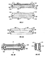
- FIG. 1 is a side view of a filter assembly.
- FIG. 2A is a side view of a filter assembly mounted on a printhead housing.
- FIG. 2B is an exploded view of the filter assembly and printhead housing of FIG. 2A .
- FIG. 3 shows an interior region of the filter assembly of FIG. 1 .
- FIG. 4A is a plan view of an upper surface of a printhead housing.
- FIG. 4B is a plan view of a lower surface of the printhead housing of FIG. 4A .
- FIG. 4C is a cross-sectional view along line A-A of the printhead housing of FIG. 4B .
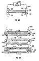
- FIG. 5A is a side view of a filter assembly showing two ink flow paths.
- FIG. 5B is an exploded view of a filter assembly and a printhead housing showing two ink flow paths.
- Figs. 5A and 5B do not represent the invention as defined in claim 1.
- FIG. 6A is a side view of a filter assembly showing a recirculation ink flow path.
- FIG. 6B is an exploded view of a filter assembly and a printhead housing showing a recirculation ink flow path.
- FIG. 1 shows an ink filter assembly 100 including an upper portion 105, lower portion 110 and a thin membrane 115 positioned between the upper portion 105 and the lower portion 110.
- the filter assembly 100 can be mounted on a printhead housing 120, as shown in FIGS. 2A and 2B .
- the printhead housing 120 is configured to house a printhead body for ejecting ink drops from an ink nozzle assembly, such as the semiconductor printhead body described in U.S. Provisional Application, Serial No. 60/510,459 , entitled "Print Head with Thin Membrane", filed October 10, 2003.
- Each of the upper and lower portions 105, 110 include at least one ink channel.
- An ink channel can function as either an inlet channel or an outlet channel, depending on the direction of ink flow, and whether the ink is recirculating through an ink nozzle assembly in fluid communication with the filter assembly 100.
- FIG. 3 shows a plan view of the lower portion 110 and a tilted side view of the upper portion 105, to illustrate the relationship of the upper and lower portions 105, 110.
- the membrane 115 is not shown.
- an interior elongated chamber is formed between the portions 105, 110 for each pair of ink channels (a pair being an ink channel in the upper portion and a corresponding ink channel in the lower portion). That is, in the embodiment shown in FIGS. 1 and 3 , there are two pairs of ink channels, and accordingly there are two interior elongated chambers formed between the upper and lower portions 105, 110 when assembled.
- an elongated chamber is approximately 4 mm wide and approximately 50 mm long.
- an upper section of a first elongated chamber 130 is formed in the upper portion 105 of the filter assembly 100, which corresponds with a lower section of the first elongated chamber 135 formed in the lower portion 110 of the filter assembly 100.
- the first elongated chamber 130-135 forms a first ink path for ink flowing between the ink channel 124 formed in the upper portion 105 and the corresponding ink channel 126 formed on the opposite end of the lower portion 110.
- an upper section of a second elongated chamber 140 is formed in the upper portion 105, which corresponds with a lower section of the second elongated chamber 145 formed in the lower portion 110.
- the second elongated chamber 140-145 forms a second ink path for ink flowing between the ink channel 122 formed in the upper portion 105 and the corresponding ink channel 128 formed on the opposite end of the lower portion 110.
- a membrane providing a permeable separator between an upper section and a lower section of an elongated chamber formed within the filter assembly 100 can filter ink as ink flows from one end of the elongated chamber to the other.
- a member 115 can be positioned between the upper and lower portions 105, 110 of the filter assembly 100 as shown in FIG. 1 , thereby separating the upper section 130 of the first elongated chamber from the lower section 135, and separating the upper section 140 of the second elongated chamber from the lower section 145.
- a separate membrane can be used to separate each of the elongated chambers.
- the elongated filter that is, the permeable separator between the upper and lower sections of an elongated chamber, has a relatively large surface area as compared to, for example, a filter placed in a perpendicular configuration to an ink flow, such as at the outlet of an ink source.
- the larger surface area results in a relatively smaller pressure drop across the filter.
- the elongated filter Reducing the pressure drop across the elongated filter is important, since the control of the printhead internal pressure is also important to the printhead's performance. Because the ink flow rate changes with printing density and speed, preferably the elongated filter has a negligible effect on the printhead's internal pressure through all operating flow rate variations. Additionally, the larger surface area provides for improved filtering of particles (i.e. contaminants), as particles ingested into the ink can be detrimental to the print quality.
- the ink filters through the membrane, thereby removing contaminants from the ink flow.
- Contaminants can block an ink nozzle opening, slow ink flow and lower the printing quality if not removed from the ink flow upstream of the ink nozzle assembly.
- the membrane includes a number of openings that are sized such that ink flow is not unnecessarily restricted, but also such that contaminants of at least a certain size are removed from the ink flow.
- the membrane can be formed from a polyimide film and openings can be laser cut into the polyimide film in at least the regions that will be used to filter ink (i.e ., regions of the film that are not in the ink path, such as regions between the edges of the upper and lower portions, may not include openings).
- FIG. 4A shows a plan view of a surface 150 of the printhead housing 120 that mates with the lower portion 110 of the filter assembly 100.
- An opening to an ink channel 155 aligns with the ink channel 126 formed in the lower portion 110 of the filter assembly 100, and a second opening to a second ink channel 160 aligns with the ink channel 128 formed in the lower portion 110.
- FIG. 4B shows a plan view of the opposite surface 152 of the printhead housing 120.
- An opening 165 is configured to house a printhead assembly, for example, a semiconductor printhead, that includes an ink nozzle assembly for injecting ink drops.
- the ink channels 155 and 160 terminate in channels 170 and 172 formed on either side of the opening 165.
- a cross-sectional view of the printhead housing 120 taken along line A-A is shown in FIG. 4C , illustrating the channels 170 and 172 formed along the length of the printhead assembly 120.
- the ink flows along the paths 171 shown from the channels 170, 172 toward and into an ink nozzle assembly within a printhead unit (not shown) that can be mounted within the opening 165.
- the upper portion 105 and the lower portion 110 of the filter assembly 100 can be joined together using any convenient means, such as an adhesive or screws. Depending on how the membrane 115 is configured, the upper portion 105 can be adhered to the membrane 115, and the membrane 115 adhered to the lower portion 110, thereby joining the upper and lower portions 105, 110 via the membrane 115. Locator pins and corresponding openings, such as the pins 118 and openings 119 shown in FIG. 3 , can be used to position the upper portion 105 relative to the lower portion 110 and to maintain the position, for example, while an adhesive hardens. The adhesive should be selected to be compatible with the ink to be used in the filter assembly 100.
- certain ultraviolet inks harden upon exposure to ultraviolet light and can be very corrosive.
- certain epoxy formulations that are resistive to such inks, and if a suitable epoxy is not used, the ink can corrode the adhesive and the filter assembly 100 may fall apart.
- the lower portion 110 of the filter assembly 100 can be mounted on the printhead housing 120 using any convenient means, such as an adhesive or screws.
- the lower portion 110 can include ink channels 126, 128 sized to fit within corresponding recesses 158, 159 formed in the surface 150 of the printhead housing 120 that mates with the lower portion 110.
- An adhesive can be used to secure the ink channels 126, 128 into the recesses 158, 159, thereby joining the lower portion 110 to the printhead housing 120 and providing a seal to prevent leaking of ink passing between the lower portion 110 and the printhead housing 120.
- a suitable adhesive should be selected that is compatible with the ink to be used in the filter assembly 100.
- ink flow patterns there are at least two ink flow patterns; in a first ink flow pattern both ink channels 122, 124 formed in the upper portion 105 operate as ink inlets and both ink channels 126, 128 formed in the lower portion 110 operate as ink outlets.
- in a second ink flow pattern one ink channel 124 in the upper portion 105 and one ink channel 128 in the lower portion 110 operate as ink inlets, while the remaining ink channel 122 in the upper portion 105 and ink channel 126 in the lower portion 110 operate as ink outlets.
- the second ink flow pattern can be a recirculation scheme.
- the first ink flow pattern is depicted with reference to a side view of the assembled upper and lower portions 105, 110 in FIG. 5A , and a view of the disassembled upper and lower portions 105, 110 of the filter assembly 100 and the printhead housing 120 in FIG. 5B .
- the ink flow initiates at an ink source 507.
- the ink for the first ink flow 505 can initiate at a first ink source and the ink for the second ink flow 510 can initiate at a different, second ink source.
- the first ink flow 505 exits from the lower portion 110 through the ink channel 128 shown on the right, and the second ink flow 510 exits through the ink channel 126 shown on the left, referred to with reference to FIGS. 5A and 5B as the left outlet channel 126 and the right outlet channel 128, respectively.
- the ink enters the left inlet channel 122 from the ink source 507.
- the ink flows through the left inlet channel 122 and enters the upper section 140 of the second elongated chamber.
- a membrane (not shown) provides a permeable separator between the upper section 140 and the lower section 145 of the second elongated chamber and filters the ink as the ink flows from left to right along the length of the second elongated chamber.
- the ink flow 505 is shown as a path in the upper section 140 of the second elongated chamber, however, it should be understood that as the ink filters through the membrane, ink also flows along the lower section 145 of the second elongated chamber, even though a path is not shown.
- the ink flows from the printhead right inlet channel 160 along the length of the channels 170 and 172 formed in the lower surface of the printhead housing 120.
- the channels 170 and 172 are in fluid communication with an ink nozzle assembly forming part of a printhead assembly (not shown), and the ink flows from the channels 170, 172 into the ink nozzle assembly and is ejected onto a printing substrate.
- the filter assembly 100 and the printhead housing 120 As the first ink flow 505.
- the ink enters the right inlet channel 124 from the ink source 507, or alternatively, from a second ink source (not shown).
- the ink flows through the right inlet channel 124 and enters the upper section 130 of the first elongated chamber.
- a membrane (not shown) provides a permeable separator between the upper section 130 and the lower section 135 of the first elongated chamber and filters the ink as the ink flows from right to left along the length of the first elongated chamber.
- the ink flow 510 is shown as a path in the upper section 130 of the first elongated chamber, however, it should be understood that as the ink filters through the membrane, ink also flows along the lower section 135 of the first elongated chamber, even though a path is not shown.
- the ink flows through the left outlet channel 126 and exits the lower portion 110 of the filter assembly 100.
- the ink flow 510 enters an ink channel 155 in the printhead housing 120, which shall be referred to with reference to FIG. 5B as the printhead left inlet channel 155.
- the ink flows from the printhead left inlet channel 155 along the channels 170 and 172 formed in the lower surface of the printhead housing 120.
- the ink flow is generated by the ejection of ink from the ink nozzle assembly.
- the printhead can include a semiconductor printhead body and a piezoelectric actuator, which pressurizes ink in a pumping chamber located along the ink path.
- the ink flow increases as more nozzles eject ink. Minimizing pressure changes due to the varying flow within the printhead is important, since preferably there is no pressure change at an inlet to each nozzle channel from zero flow ( i.e ., no nozzles ejecting ink) to full flow ( i.e ., all nozzles ejecting ink).
- the ink flow can be generated by use of an external pump, for example, for filling, purging, flushing, cleaning or recirculating the ink through the printhead and filter assembly 100.
- FIGS. 5A and 5B show a filter assembly 100 configured with two inlet ink flows 505, 510, both directed toward a printhead housing 120 in fluid communication with an ink nozzle assembly.
- the configuration does not recirculate the ink, and once the ink enters the filter assembly 100 and the ink nozzle assembly, the ink remains there until ejected during an ink jet printing process.
- This configuration is appropriate in certain applications where the temperature of the ink can be the same as the ambient temperature.
- the filter assembly 100, the printhead housing 120 and the printhead unit including the ink nozzle assembly can be heated to maintain the ink at a temperature above the ambient temperature, although typically only a few degrees higher than the ambient temperature.
- the ink must be kept moving, so as not to coagulate, and/or must be kept at a temperature significantly above the ambient temperature. In such applications, a recirculation scheme may be more appropriate.
- FIGS. 6A and 6B show a filter assembly 100 configured with one ink flow 605 entering the filter assembly 100 from an ink source 607 and exiting into the printhead housing 120, which is in fluid communication with an ink nozzle assembly.
- the ink flows through the printhead housing 120 where some of the ink is consumed by the ink nozzle assembly ( i.e ., used during an ink jet printing process).
- the remaining ink flows through the printhead housing 120 and back into the filter assembly 100 and finally exits the filter assembly 100 and returns to the ink source 607.
- the ink flow 605 enters the filter assembly 100 from the ink source 607 through the ink channel 124 formed in the upper portion 105.
- the ink flows through the ink channel 124 into the upper section 130 of the first elongated chamber.
- the ink is filtered through a membrane (not shown) providing a permeable separator between the upper section 130 and the lower section 135 of the first elongated chamber.
- the ink flow 605 is shown as a path in the upper section 130 of the first elongated chamber, however, it should be understood that as the ink filters through the membrane, ink also flows along the lower section 135 of the first elongated chamber, even though a path is not shown.
- the ink flows through the ink channel 126 and exits the lower portion 110 of the filter assembly 100.
- the ink flow 605 enters an ink channel 155 in the printhead housing 120, and flows from the ink channel 155 along the channels 170 and 172 formed in the lower surface of the printhead housing 120. Some of the ink flow 605 enters a printhead unit housed within the printhead housing 120 and is consumed by an ink nozzle assembly therein. The remaining ink flows from the channels 170, 172 toward and into the ink channel 160.
- the ink flow 605 exits the printhead housing 120 and enters the lower portion 110 of the filter assembly 100 through the ink channel 128.
- the ink flows from the ink channel 128 into the lower section 145 of the second elongated chamber.
- the ink can be filtered by a membrane (not shown) providing a permeable separator between the upper and lower sections 140, 145 of the second elongated chamber.
- a membrane not shown
- the ink flow 605 exits the filter assembly 100 through the ink channel 122 formed in the upper portion 105 and returns to the ink source 607.
- openings provided in the region of the membrane separating the upper and lower sections 130, 135 of the first elongated chamber can be a different size than openings provided in the region of the membrane separating the upper and lower sections 140, 145 of the second elongated chamber.
- the ink flow 605 can be filtered to one degree while in route to the printhead housing 120 and to a second degree or not at all ( e.g ., a lesser degree) while in route back to the ink source 607.
- the ink channels 122 and 124 formed in the upper portion 105 align with the ink channels 126 and 128 formed in the lower portion 110.
- an impermeable separator is positioned to separate each of the ink channels 122, 124 formed in the upper portion 105 from the corresponding ink channels 126, 128 formed in the lower portion 110.
- the membrane providing a permeable separator between the upper and lower sections of the elongated chambers can form the impermeable separator between each pair of ink channels.
- the membrane is a polyimide film with openings laser cut in the film to provide permeability in some regions, then other regions of the membrane can remain uncut, and therefore impermeable, to separate a pair of ink channels.
- the ink channels formed in the upper and lower portions 105, 110 of the filter assembly 100 can be configured such that they do not align, thereby eliminating the need for an impermeable separator to be positioned therebetween.
- the embodiment of the filter assembly shown in FIGS. 1 , 3 , 5A-B and 6A-B includes two elongated chambers.
- the filter assembly can include a single elongated chamber or more than two elongated chambers.
- the membrane forming an impermeable separator between an upper and lower section of an elongated chamber can be formed in any convenient manner.
- the membrane is formed from a polyimide film with openings cut into the polyimide film to provide permeability, for example, by laser cutting.
- a polyimide film such as Kapton ® available from DuPont High Performance Materials of Ohio, can be used, and in one embodiment can be cut to 50% open.
- the openings can have a diameter size of approximately 10 to 75 microns, as an example. The size of the openings depends on the size of the nozzles included in the ink nozzle assembly. Preferably the openings are smaller than the nozzle diameter to prevent blockage of the nozzles by contaminants in the ink.
- the membrane can be a thin, metal substrate perforated in regions intended for filtering, formed by electroforming, for example, using nickel or a nickel alloy. Electroforming can be done with a photo imaged pattern and subsequent additive selective plating to grow the predefined shape with the openings.
- the membrane can a thin, metal substrate, for example, stainless steel, a ferritic stainless steel or ferritic alloy, with openings etched into the metal substrate using a chemical etching process.
- the membrane can be a screen mesh, for example, stainless steel with 20% open.
- a die cut B-stage epoxy adhesive film is used to join the upper portion 105 and lower portion 110 of the filter assembly 100. The adhesive film is die cut such that areas where there can be ink flow are removed.
- the film can function as a barrier.
- An adhesive film can be used on each side of the filter, to adhere the filter to both the upper and lower portions 105, 110.
- the filter assembly and the printhead housing can be formed from any convenient material.
- a liquid crystal polymer can provide suitable chemical resistance to ink flowing through the filter assembly and has a low thermal expansion coefficient.
- the thermal expansion coefficient for each component in the filter assembly and the printhead housing match, so as to prevent misalignment and the like due to differing thermal expansion properties.
- the membrane can be adhered to the filter assembly, for example, using a B-stage epoxy film applied to both sides of the membrane to adhere to both the upper and lower portions of the filter assembly.
Landscapes
- Particle Formation And Scattering Control In Inkjet Printers (AREA)
- Ink Jet (AREA)
- Separation Using Semi-Permeable Membranes (AREA)
Applications Claiming Priority (2)
| Application Number | Priority Date | Filing Date | Title |
|---|---|---|---|
| US10/836,456 US7448741B2 (en) | 2004-04-30 | 2004-04-30 | Elongated filter assembly |
| PCT/US2005/014370 WO2005110019A2 (en) | 2004-04-30 | 2005-04-26 | Elongated filter assembly |
Publications (2)
| Publication Number | Publication Date |
|---|---|
| EP1750947A2 EP1750947A2 (en) | 2007-02-14 |
| EP1750947B1 true EP1750947B1 (en) | 2012-09-26 |
Family
ID=35186628
Family Applications (1)
| Application Number | Title | Priority Date | Filing Date |
|---|---|---|---|
| EP05746604A Expired - Lifetime EP1750947B1 (en) | 2004-04-30 | 2005-04-26 | Elongated filter assembly |
Country Status (6)
| Country | Link |
|---|---|
| US (1) | US7448741B2 (enExample) |
| EP (1) | EP1750947B1 (enExample) |
| JP (1) | JP4590451B2 (enExample) |
| KR (1) | KR20070009728A (enExample) |
| CN (1) | CN1968817B (enExample) |
| WO (1) | WO2005110019A2 (enExample) |
Families Citing this family (19)
| Publication number | Priority date | Publication date | Assignee | Title |
|---|---|---|---|---|
| DE10360274A1 (de) * | 2003-12-18 | 2005-06-02 | Tesa Ag | Optischer Datenspeicher |
| US8231202B2 (en) * | 2004-04-30 | 2012-07-31 | Fujifilm Dimatix, Inc. | Droplet ejection apparatus alignment |
| KR20070007384A (ko) * | 2004-05-03 | 2007-01-15 | 후지필름 디마틱스, 인크. | 가요성 프린트헤드 회로 |
| US7661798B2 (en) * | 2005-11-25 | 2010-02-16 | Canon Finetech Inc. | Liquid ejection head, liquid supply apparatus, liquid ejection apparatus, and liquid supply method |
| US7758177B2 (en) * | 2007-03-21 | 2010-07-20 | Silverbrook Research Pty Ltd | High flowrate filter for inkjet printhead |
| JP5181898B2 (ja) * | 2007-08-10 | 2013-04-10 | セイコーエプソン株式会社 | 液体噴射ヘッド |
| JP4993130B2 (ja) * | 2008-02-29 | 2012-08-08 | セイコーエプソン株式会社 | 液体噴射ヘッド及び液体噴射装置 |
| USD653284S1 (en) | 2009-07-02 | 2012-01-31 | Fujifilm Dimatix, Inc. | Printhead frame |
| US8517508B2 (en) * | 2009-07-02 | 2013-08-27 | Fujifilm Dimatix, Inc. | Positioning jetting assemblies |
| USD652446S1 (en) | 2009-07-02 | 2012-01-17 | Fujifilm Dimatix, Inc. | Printhead assembly |
| JP5539008B2 (ja) * | 2010-05-14 | 2014-07-02 | キヤノン株式会社 | 液体吐出ヘッド、液体吐出装置及び液体充填方法 |
| JP6028513B2 (ja) * | 2011-12-20 | 2016-11-16 | 株式会社リコー | 液滴吐出ヘッド、画像形成装置、及び液滴吐出ヘッドの製造方法 |
| JP6119276B2 (ja) * | 2013-02-06 | 2017-04-26 | 株式会社リコー | 液体吐出ヘッド、画像形成装置 |
| WO2016068989A1 (en) | 2014-10-31 | 2016-05-06 | Hewlett-Packard Development Company, L.P. | Fluid ejection device |
| CN107073953B (zh) | 2014-10-31 | 2018-09-04 | 惠普发展公司,有限责任合伙企业 | 流体喷射设备 |
| US9278542B1 (en) * | 2015-06-29 | 2016-03-08 | Xerox Corporation | Replaceable, high-temperature, multi-channel, externally attached fluidic filter |
| US10046570B2 (en) | 2016-01-13 | 2018-08-14 | Océ Holding B.V. | Filter device for filtering ink and ink supply system for printing apparatus |
| ES2714727T3 (es) * | 2016-04-12 | 2019-05-29 | Ebs Ink Jet Systeme Gmbh | Impresora de inyección de tinta para imprimir sobre mercancías con un filtro y filtro de dicha impresora de inyección de tinta |
| US12300480B2 (en) | 2021-01-15 | 2025-05-13 | Elemental Scientific, Inc. | Shaped-channel scanning nozzle for scanning of a material surface |
Family Cites Families (43)
| Publication number | Priority date | Publication date | Assignee | Title |
|---|---|---|---|---|
| US4527175A (en) | 1981-12-02 | 1985-07-02 | Matsushita Electric Industrial Company, Limited | Ink supply system for nonimpact printers |
| US4433341A (en) | 1982-06-07 | 1984-02-21 | Ncr Corporation | Ink level control for ink jet printer |
| US4661458A (en) * | 1983-08-31 | 1987-04-28 | Cell Environmental Systems, Ltd. | Cell culture system |
| DE3446998A1 (de) | 1983-12-26 | 1985-07-04 | Canon K.K., Tokio/Tokyo | Tintenstrahl-aufzeichnungsgeraet |
| US4929963A (en) | 1988-09-02 | 1990-05-29 | Hewlett-Packard Company | Ink delivery system for inkjet printer |
| CA2009631C (en) | 1989-02-17 | 1994-09-20 | Shigeo Nonoyama | Pressure damper of an ink jet printer |
| US5265315A (en) | 1990-11-20 | 1993-11-30 | Spectra, Inc. | Method of making a thin-film transducer ink jet head |
| JP3161635B2 (ja) * | 1991-10-17 | 2001-04-25 | ソニー株式会社 | インクジェットプリントヘッド及びインクジェットプリンタ |
| US6000792A (en) * | 1992-09-02 | 1999-12-14 | Canon Kabushiki Kaisha | Ink jet apparatus provided with an improved recovery mechanism |
| US5489930A (en) * | 1993-04-30 | 1996-02-06 | Tektronix, Inc. | Ink jet head with internal filter |
| US5610645A (en) * | 1993-04-30 | 1997-03-11 | Tektronix, Inc. | Ink jet head with channel filter |
| JPH0717050A (ja) | 1993-07-02 | 1995-01-20 | Brother Ind Ltd | インクジェットプリンタにおけるフィルタ装置 |
| US6343857B1 (en) | 1994-02-04 | 2002-02-05 | Hewlett-Packard Company | Ink circulation in ink-jet pens |
| US5751300A (en) | 1994-02-04 | 1998-05-12 | Hewlett-Packard Company | Ink delivery system for a printer |
| US5724082A (en) | 1994-04-22 | 1998-03-03 | Specta, Inc. | Filter arrangement for ink jet head |
| FR2729891B1 (fr) | 1995-01-31 | 1997-04-11 | Imaje Sa | Dispositif de modulation equipe d'un filtre de securite pour tete d'impression a jet d'encre |
| US5936650A (en) | 1995-05-24 | 1999-08-10 | Hewlett Packard Company | Ink delivery system for ink-jet pens |
| JPH10151761A (ja) | 1996-11-21 | 1998-06-09 | Brother Ind Ltd | インクジェット記録装置 |
| DE19704465A1 (de) * | 1997-02-06 | 1998-08-13 | Sartorius Gmbh | Filtrationseinheit mit einem plissierten Filterelement |
| US5782184A (en) | 1997-03-12 | 1998-07-21 | Raster Graphics, Incorporated | Printer head carriage and method for aligning printer heads on a printer head carriage |
| US6672706B2 (en) | 1997-07-15 | 2004-01-06 | Silverbrook Research Pty Ltd | Wide format pagewidth inkjet printer |
| US6350013B1 (en) | 1997-10-28 | 2002-02-26 | Hewlett-Packard Company | Carrier positioning for wide-array inkjet printhead assembly |
| DE19752376A1 (de) * | 1997-11-26 | 1999-05-27 | Mann & Hummel Filter | Filter |
| US6217164B1 (en) * | 1997-12-09 | 2001-04-17 | Brother Kogyo Kabushiki Kaisha | Ink jet recorder |
| CA2344999A1 (en) * | 1998-10-12 | 2000-04-20 | Xaar Technology Limited | Ink supply filter |
| JP2000238270A (ja) * | 1998-12-22 | 2000-09-05 | Canon Inc | インクジェット記録ヘッド及びインクジェット記録ヘッドの製造方法 |
| US6084618A (en) | 1999-07-22 | 2000-07-04 | Lexmark International, Inc. | Filter for an inkjet printhead |
| GB0003760D0 (en) | 2000-02-17 | 2000-04-05 | Xaar Technology Ltd | Droplet deposition apparatus |
| JP2002178541A (ja) * | 2000-02-28 | 2002-06-26 | Seiko Epson Corp | 記録ヘッドユニット |
| AUPQ595700A0 (en) | 2000-03-02 | 2000-03-23 | Silverbrook Research Pty Ltd | Alignment module for printheads |
| AUPQ605900A0 (en) | 2000-03-06 | 2000-03-30 | Silverbrook Research Pty Ltd | Thermal expansion compensation for printhead assemblies |
| US6499823B2 (en) * | 2000-06-15 | 2002-12-31 | Canon Kabushiki Kaisha | Ink jet recording head having substrate and ceiling plate base pressed together by base plate and ink supply member |
| JP4523133B2 (ja) | 2000-08-31 | 2010-08-11 | セイコーインスツル株式会社 | 記録ユニット及びインクジェット式記録装置 |
| US6655786B1 (en) | 2000-10-20 | 2003-12-02 | Silverbrook Research Pty Ltd | Mounting of printhead in support member of six color inkjet modular printhead |
| US6428141B1 (en) | 2001-04-23 | 2002-08-06 | Hewlett-Packard Company | Reference datums for inkjet printhead assembly |
| DE60237438D1 (de) * | 2001-05-09 | 2010-10-07 | Panasonic Corp | Tintenstrahlvorrichtung und herstellungsverfahren eines elektronischen bauteils mit einer solchen vorrichtung |
| US6685299B2 (en) | 2001-05-31 | 2004-02-03 | Brother Kogyo Kabushiki Kaisha | Ink jet head |
| JP3800995B2 (ja) | 2001-06-26 | 2006-07-26 | ブラザー工業株式会社 | インクジェット記録装置 |
| US6467874B1 (en) | 2001-08-27 | 2002-10-22 | Hewlett-Packard Company | Pen positioning in page wide array printers |
| JP2003237083A (ja) | 2002-02-15 | 2003-08-26 | Canon Inc | 液体噴射記録ヘッド、および、それを備えた液体噴射記録装置 |
| EP1336492B1 (en) | 2002-02-15 | 2006-01-18 | Brother Kogyo Kabushiki Kaisha | Method of fabricating ink-jet head |
| US6752493B2 (en) | 2002-04-30 | 2004-06-22 | Hewlett-Packard Development Company, L.P. | Fluid delivery techniques with improved reliability |
| JP3995996B2 (ja) | 2002-06-21 | 2007-10-24 | エスアイアイ・プリンテック株式会社 | インクジェットヘッド及びインクジェット式記録装置 |
-
2004
- 2004-04-30 US US10/836,456 patent/US7448741B2/en not_active Expired - Lifetime
-
2005
- 2005-04-26 WO PCT/US2005/014370 patent/WO2005110019A2/en not_active Ceased
- 2005-04-26 EP EP05746604A patent/EP1750947B1/en not_active Expired - Lifetime
- 2005-04-26 KR KR1020067025306A patent/KR20070009728A/ko not_active Withdrawn
- 2005-04-26 CN CN2005800193018A patent/CN1968817B/zh not_active Expired - Fee Related
- 2005-04-26 JP JP2007510914A patent/JP4590451B2/ja not_active Expired - Fee Related
Also Published As
| Publication number | Publication date |
|---|---|
| JP4590451B2 (ja) | 2010-12-01 |
| US7448741B2 (en) | 2008-11-11 |
| WO2005110019A3 (en) | 2006-06-15 |
| JP2007535429A (ja) | 2007-12-06 |
| KR20070009728A (ko) | 2007-01-18 |
| EP1750947A2 (en) | 2007-02-14 |
| US20050243145A1 (en) | 2005-11-03 |
| WO2005110019A2 (en) | 2005-11-24 |
| CN1968817A (zh) | 2007-05-23 |
| CN1968817B (zh) | 2011-06-01 |
Similar Documents
| Publication | Publication Date | Title |
|---|---|---|
| EP1750947B1 (en) | Elongated filter assembly | |
| EP1744896B1 (en) | Recirculation assembly | |
| US6464347B2 (en) | Laser ablated filter | |
| US5724082A (en) | Filter arrangement for ink jet head | |
| EP0675000B1 (en) | Ink jet printhead with built in filter structure | |
| EP0640481B1 (en) | Ink jet print head | |
| US8684507B2 (en) | Liquid ejecting head, liquid ejecting unit, and liquid ejecting apparatus | |
| JP2000141701A (ja) | プリントシステムおよびプリント方法 | |
| JP2009285900A (ja) | ライン型ヘッドユニット | |
| KR20170114926A (ko) | 잉크젯 프린트 헤드에서의 단일 분사 재순환 | |
| US20180056647A1 (en) | Single jet recirculation in an inkjet print head | |
| US6779877B2 (en) | Ink jet printhead having a channel plate with integral filter | |
| US6280013B1 (en) | Heat exchanger for an inkjet printhead | |
| US8690302B2 (en) | Bubble removal for ink jet printing | |
| US8465140B2 (en) | Printhead including reinforced liquid chamber | |
| US8465141B2 (en) | Liquid chamber reinforcement in contact with filter | |
| US20110261124A1 (en) | Printhead including filter associated with each nozzle | |
| US6817708B2 (en) | Conical or cylindrical laser ablated filter | |
| CN113272146B (zh) | 流体供给孔端口尺寸 | |
| CN1964852A (zh) | 循环组件 | |
| JP2002178513A (ja) | 記録ヘッドと記録ヘッドの製造方法及びインクジェット記録装置 |
Legal Events
| Date | Code | Title | Description |
|---|---|---|---|
| PUAI | Public reference made under article 153(3) epc to a published international application that has entered the european phase |
Free format text: ORIGINAL CODE: 0009012 |
|
| 17P | Request for examination filed |
Effective date: 20061114 |
|
| AK | Designated contracting states |
Kind code of ref document: A2 Designated state(s): AT BE BG CH CY CZ DE DK EE ES FI FR GB GR HU IE IS IT LI LT LU MC NL PL PT RO SE SI SK TR |
|
| DAX | Request for extension of the european patent (deleted) | ||
| 17Q | First examination report despatched |
Effective date: 20110113 |
|
| GRAP | Despatch of communication of intention to grant a patent |
Free format text: ORIGINAL CODE: EPIDOSNIGR1 |
|
| GRAS | Grant fee paid |
Free format text: ORIGINAL CODE: EPIDOSNIGR3 |
|
| GRAA | (expected) grant |
Free format text: ORIGINAL CODE: 0009210 |
|
| AK | Designated contracting states |
Kind code of ref document: B1 Designated state(s): AT BE BG CH CY CZ DE DK EE ES FI FR GB GR HU IE IS IT LI LT LU MC NL PL PT RO SE SI SK TR |
|
| REG | Reference to a national code |
Ref country code: GB Ref legal event code: FG4D |
|
| REG | Reference to a national code |
Ref country code: CH Ref legal event code: EP |
|
| REG | Reference to a national code |
Ref country code: AT Ref legal event code: REF Ref document number: 576844 Country of ref document: AT Kind code of ref document: T Effective date: 20121015 |
|
| REG | Reference to a national code |
Ref country code: IE Ref legal event code: FG4D |
|
| REG | Reference to a national code |
Ref country code: DE Ref legal event code: R096 Ref document number: 602005036295 Country of ref document: DE Effective date: 20121122 |
|
| PG25 | Lapsed in a contracting state [announced via postgrant information from national office to epo] |
Ref country code: FI Free format text: LAPSE BECAUSE OF FAILURE TO SUBMIT A TRANSLATION OF THE DESCRIPTION OR TO PAY THE FEE WITHIN THE PRESCRIBED TIME-LIMIT Effective date: 20120926 Ref country code: LT Free format text: LAPSE BECAUSE OF FAILURE TO SUBMIT A TRANSLATION OF THE DESCRIPTION OR TO PAY THE FEE WITHIN THE PRESCRIBED TIME-LIMIT Effective date: 20120926 |
|
| REG | Reference to a national code |
Ref country code: AT Ref legal event code: MK05 Ref document number: 576844 Country of ref document: AT Kind code of ref document: T Effective date: 20120926 |
|
| REG | Reference to a national code |
Ref country code: LT Ref legal event code: MG4D Effective date: 20120926 |
|
| REG | Reference to a national code |
Ref country code: NL Ref legal event code: VDEP Effective date: 20120926 |
|
| PG25 | Lapsed in a contracting state [announced via postgrant information from national office to epo] |
Ref country code: SI Free format text: LAPSE BECAUSE OF FAILURE TO SUBMIT A TRANSLATION OF THE DESCRIPTION OR TO PAY THE FEE WITHIN THE PRESCRIBED TIME-LIMIT Effective date: 20120926 Ref country code: SE Free format text: LAPSE BECAUSE OF FAILURE TO SUBMIT A TRANSLATION OF THE DESCRIPTION OR TO PAY THE FEE WITHIN THE PRESCRIBED TIME-LIMIT Effective date: 20120926 Ref country code: GR Free format text: LAPSE BECAUSE OF FAILURE TO SUBMIT A TRANSLATION OF THE DESCRIPTION OR TO PAY THE FEE WITHIN THE PRESCRIBED TIME-LIMIT Effective date: 20121227 |
|
| PG25 | Lapsed in a contracting state [announced via postgrant information from national office to epo] |
Ref country code: IS Free format text: LAPSE BECAUSE OF FAILURE TO SUBMIT A TRANSLATION OF THE DESCRIPTION OR TO PAY THE FEE WITHIN THE PRESCRIBED TIME-LIMIT Effective date: 20130126 Ref country code: ES Free format text: LAPSE BECAUSE OF FAILURE TO SUBMIT A TRANSLATION OF THE DESCRIPTION OR TO PAY THE FEE WITHIN THE PRESCRIBED TIME-LIMIT Effective date: 20130106 Ref country code: CZ Free format text: LAPSE BECAUSE OF FAILURE TO SUBMIT A TRANSLATION OF THE DESCRIPTION OR TO PAY THE FEE WITHIN THE PRESCRIBED TIME-LIMIT Effective date: 20120926 Ref country code: RO Free format text: LAPSE BECAUSE OF FAILURE TO SUBMIT A TRANSLATION OF THE DESCRIPTION OR TO PAY THE FEE WITHIN THE PRESCRIBED TIME-LIMIT Effective date: 20120926 Ref country code: BE Free format text: LAPSE BECAUSE OF FAILURE TO SUBMIT A TRANSLATION OF THE DESCRIPTION OR TO PAY THE FEE WITHIN THE PRESCRIBED TIME-LIMIT Effective date: 20120926 Ref country code: NL Free format text: LAPSE BECAUSE OF FAILURE TO SUBMIT A TRANSLATION OF THE DESCRIPTION OR TO PAY THE FEE WITHIN THE PRESCRIBED TIME-LIMIT Effective date: 20120926 Ref country code: EE Free format text: LAPSE BECAUSE OF FAILURE TO SUBMIT A TRANSLATION OF THE DESCRIPTION OR TO PAY THE FEE WITHIN THE PRESCRIBED TIME-LIMIT Effective date: 20120926 |
|
| PG25 | Lapsed in a contracting state [announced via postgrant information from national office to epo] |
Ref country code: CY Free format text: LAPSE BECAUSE OF FAILURE TO SUBMIT A TRANSLATION OF THE DESCRIPTION OR TO PAY THE FEE WITHIN THE PRESCRIBED TIME-LIMIT Effective date: 20120926 Ref country code: PL Free format text: LAPSE BECAUSE OF FAILURE TO SUBMIT A TRANSLATION OF THE DESCRIPTION OR TO PAY THE FEE WITHIN THE PRESCRIBED TIME-LIMIT Effective date: 20120926 Ref country code: SK Free format text: LAPSE BECAUSE OF FAILURE TO SUBMIT A TRANSLATION OF THE DESCRIPTION OR TO PAY THE FEE WITHIN THE PRESCRIBED TIME-LIMIT Effective date: 20120926 Ref country code: PT Free format text: LAPSE BECAUSE OF FAILURE TO SUBMIT A TRANSLATION OF THE DESCRIPTION OR TO PAY THE FEE WITHIN THE PRESCRIBED TIME-LIMIT Effective date: 20130128 |
|
| PG25 | Lapsed in a contracting state [announced via postgrant information from national office to epo] |
Ref country code: AT Free format text: LAPSE BECAUSE OF FAILURE TO SUBMIT A TRANSLATION OF THE DESCRIPTION OR TO PAY THE FEE WITHIN THE PRESCRIBED TIME-LIMIT Effective date: 20120926 |
|
| PG25 | Lapsed in a contracting state [announced via postgrant information from national office to epo] |
Ref country code: BG Free format text: LAPSE BECAUSE OF FAILURE TO SUBMIT A TRANSLATION OF THE DESCRIPTION OR TO PAY THE FEE WITHIN THE PRESCRIBED TIME-LIMIT Effective date: 20121226 Ref country code: DK Free format text: LAPSE BECAUSE OF FAILURE TO SUBMIT A TRANSLATION OF THE DESCRIPTION OR TO PAY THE FEE WITHIN THE PRESCRIBED TIME-LIMIT Effective date: 20120926 |
|
| PLBE | No opposition filed within time limit |
Free format text: ORIGINAL CODE: 0009261 |
|
| STAA | Information on the status of an ep patent application or granted ep patent |
Free format text: STATUS: NO OPPOSITION FILED WITHIN TIME LIMIT |
|
| PG25 | Lapsed in a contracting state [announced via postgrant information from national office to epo] |
Ref country code: IT Free format text: LAPSE BECAUSE OF FAILURE TO SUBMIT A TRANSLATION OF THE DESCRIPTION OR TO PAY THE FEE WITHIN THE PRESCRIBED TIME-LIMIT Effective date: 20120926 |
|
| 26N | No opposition filed |
Effective date: 20130627 |
|
| REG | Reference to a national code |
Ref country code: DE Ref legal event code: R097 Ref document number: 602005036295 Country of ref document: DE Effective date: 20130627 |
|
| PG25 | Lapsed in a contracting state [announced via postgrant information from national office to epo] |
Ref country code: MC Free format text: LAPSE BECAUSE OF FAILURE TO SUBMIT A TRANSLATION OF THE DESCRIPTION OR TO PAY THE FEE WITHIN THE PRESCRIBED TIME-LIMIT Effective date: 20120926 |
|
| REG | Reference to a national code |
Ref country code: CH Ref legal event code: PL |
|
| REG | Reference to a national code |
Ref country code: IE Ref legal event code: MM4A |
|
| PG25 | Lapsed in a contracting state [announced via postgrant information from national office to epo] |
Ref country code: CH Free format text: LAPSE BECAUSE OF NON-PAYMENT OF DUE FEES Effective date: 20130430 Ref country code: LI Free format text: LAPSE BECAUSE OF NON-PAYMENT OF DUE FEES Effective date: 20130430 |
|
| PG25 | Lapsed in a contracting state [announced via postgrant information from national office to epo] |
Ref country code: IE Free format text: LAPSE BECAUSE OF NON-PAYMENT OF DUE FEES Effective date: 20130426 |
|
| PG25 | Lapsed in a contracting state [announced via postgrant information from national office to epo] |
Ref country code: TR Free format text: LAPSE BECAUSE OF FAILURE TO SUBMIT A TRANSLATION OF THE DESCRIPTION OR TO PAY THE FEE WITHIN THE PRESCRIBED TIME-LIMIT Effective date: 20120926 |
|
| PG25 | Lapsed in a contracting state [announced via postgrant information from national office to epo] |
Ref country code: HU Free format text: LAPSE BECAUSE OF FAILURE TO SUBMIT A TRANSLATION OF THE DESCRIPTION OR TO PAY THE FEE WITHIN THE PRESCRIBED TIME-LIMIT; INVALID AB INITIO Effective date: 20050426 Ref country code: LU Free format text: LAPSE BECAUSE OF NON-PAYMENT OF DUE FEES Effective date: 20130426 |
|
| REG | Reference to a national code |
Ref country code: FR Ref legal event code: PLFP Year of fee payment: 12 |
|
| REG | Reference to a national code |
Ref country code: FR Ref legal event code: PLFP Year of fee payment: 13 |
|
| REG | Reference to a national code |
Ref country code: FR Ref legal event code: PLFP Year of fee payment: 14 |
|
| PGFP | Annual fee paid to national office [announced via postgrant information from national office to epo] |
Ref country code: FR Payment date: 20230309 Year of fee payment: 19 |
|
| PGFP | Annual fee paid to national office [announced via postgrant information from national office to epo] |
Ref country code: GB Payment date: 20230302 Year of fee payment: 19 |
|
| PGFP | Annual fee paid to national office [announced via postgrant information from national office to epo] |
Ref country code: DE Payment date: 20230228 Year of fee payment: 19 |
|
| REG | Reference to a national code |
Ref country code: DE Ref legal event code: R119 Ref document number: 602005036295 Country of ref document: DE |
|
| GBPC | Gb: european patent ceased through non-payment of renewal fee |
Effective date: 20240426 |
|
| PG25 | Lapsed in a contracting state [announced via postgrant information from national office to epo] |
Ref country code: DE Free format text: LAPSE BECAUSE OF NON-PAYMENT OF DUE FEES Effective date: 20241105 |
|
| PG25 | Lapsed in a contracting state [announced via postgrant information from national office to epo] |
Ref country code: GB Free format text: LAPSE BECAUSE OF NON-PAYMENT OF DUE FEES Effective date: 20240426 |
|
| PG25 | Lapsed in a contracting state [announced via postgrant information from national office to epo] |
Ref country code: FR Free format text: LAPSE BECAUSE OF NON-PAYMENT OF DUE FEES Effective date: 20240430 |
|
| PG25 | Lapsed in a contracting state [announced via postgrant information from national office to epo] |
Ref country code: GB Free format text: LAPSE BECAUSE OF NON-PAYMENT OF DUE FEES Effective date: 20240426 Ref country code: FR Free format text: LAPSE BECAUSE OF NON-PAYMENT OF DUE FEES Effective date: 20240430 Ref country code: DE Free format text: LAPSE BECAUSE OF NON-PAYMENT OF DUE FEES Effective date: 20241105 |