EP1750284B1 - Abdeckelement für den Reaktorkern eines Siedewasserreaktors - Google Patents
Abdeckelement für den Reaktorkern eines Siedewasserreaktors Download PDFInfo
- Publication number
- EP1750284B1 EP1750284B1 EP06012837.8A EP06012837A EP1750284B1 EP 1750284 B1 EP1750284 B1 EP 1750284B1 EP 06012837 A EP06012837 A EP 06012837A EP 1750284 B1 EP1750284 B1 EP 1750284B1
- Authority
- EP
- European Patent Office
- Prior art keywords
- boiling
- core
- bearing ring
- reactor
- water reactor
- Prior art date
- Legal status (The legal status is an assumption and is not a legal conclusion. Google has not performed a legal analysis and makes no representation as to the accuracy of the status listed.)
- Not-in-force
Links
Images
Classifications
-
- G—PHYSICS
- G21—NUCLEAR PHYSICS; NUCLEAR ENGINEERING
- G21C—NUCLEAR REACTORS
- G21C15/00—Cooling arrangements within the pressure vessel containing the core; Selection of specific coolants
- G21C15/16—Cooling arrangements within the pressure vessel containing the core; Selection of specific coolants comprising means for separating liquid and steam
-
- G—PHYSICS
- G21—NUCLEAR PHYSICS; NUCLEAR ENGINEERING
- G21C—NUCLEAR REACTORS
- G21C13/00—Pressure vessels; Containment vessels; Containment in general
- G21C13/02—Details
- G21C13/06—Sealing-plugs
- G21C13/073—Closures for reactor-vessels, e.g. rotatable
-
- G—PHYSICS
- G21—NUCLEAR PHYSICS; NUCLEAR ENGINEERING
- G21C—NUCLEAR REACTORS
- G21C5/00—Moderator or core structure; Selection of materials for use as moderator
- G21C5/02—Details
- G21C5/10—Means for supporting the complete structure
-
- Y—GENERAL TAGGING OF NEW TECHNOLOGICAL DEVELOPMENTS; GENERAL TAGGING OF CROSS-SECTIONAL TECHNOLOGIES SPANNING OVER SEVERAL SECTIONS OF THE IPC; TECHNICAL SUBJECTS COVERED BY FORMER USPC CROSS-REFERENCE ART COLLECTIONS [XRACs] AND DIGESTS
- Y02—TECHNOLOGIES OR APPLICATIONS FOR MITIGATION OR ADAPTATION AGAINST CLIMATE CHANGE
- Y02E—REDUCTION OF GREENHOUSE GAS [GHG] EMISSIONS, RELATED TO ENERGY GENERATION, TRANSMISSION OR DISTRIBUTION
- Y02E30/00—Energy generation of nuclear origin
- Y02E30/30—Nuclear fission reactors
Definitions
- the invention relates to a cover for the reactor core of a nuclear facility. It further relates to a nuclear reactor having such a cover element. Similar devices are in US3711371 and in DE 1564783 shown.
- Boiling-water reactors have a reactor pressure vessel filled with cooling water, in which the reactor core formed from fuel elements is arranged.
- the reactor core is usually enclosed laterally by a cylindrical core shell.
- the fuel elements are held in a so-called core grid, which is arranged at the upper end of the core sheath.
- the reactor core is closed with a generally dome-shaped or hemispherical core cover.
- In the core cover a number of passages is introduced.
- the cooling water in the reactor pressure vessel is heated and partially evaporated due to the nuclear reaction taking place in the reactor core.
- the water-vapor mixture produced in this way enters through the passage openings in the core cover into the so-called standpipes of the water-steam separator connected thereto. Then it is passed into the steam dryer. Thereafter, the standing under high pressure and high temperature, dried live steam is led out via a main steam line from the pressure vessel and fed to generate electrical energy coupled to a generator steam turbine.
- the core lid is usually subject to particularly high demands in terms of pressure resistance and tightness. It is therefore usually designed as a monolithic forging.
- the core cover For maintenance work on the reactor core and in particular for an exchange of fuel elements, the core cover must also be detachably fastened to the core casing or to the core grid. Furthermore is for a favorable influencing and calming of the steam flow before their entry into the standpipes of the water-steam separator between the core cover and the core grid provided a sufficiently large-sized vertical distance. This distance can be realized in that on the dome-shaped cover shell of the core cover an intermediate ring also referred to as a support ring is formed, wherein the intermediate ring is fixed in the operating state of the reactor at its lower edge on the core grid or on the cylindrical core jacket.
- such a design of the core cover as a monolithic forging is problematic and associated with high manufacturing costs due to its size and its complex shape.
- the invention is therefore an object of the invention to provide a cover for the reactor core of a nuclear facility that allows safe and tight closure of the reactor core in the operating state at the given geometrical boundary conditions and easy and inexpensive held production.
- the cover should also be easily disassembled during maintenance or loading operations, while offering good intervention options in the reactor core. This object is achieved by an arrangement according to claim 1.
- the invention is based on the consideration that the cover should be at least two parts in terms of a reasonable manufacturing effort, as a separate items provided a core cover with a cover shell in the form of a flattened hemisphere (calotte) and a fit with the lid connectable support ring are.
- the connection between the two components should be such that the support ring can be lifted together with the core cover from the reactor pressure vessel during dismantling of the core cover, such as fuel assembly, in one operation together with the core cover, so that there are particularly good accessibility in the reactor cores with correspondingly large freedom of movement.
- the core cover could be welded to the support ring for this purpose. But this large-volume welds are required, which are associated with time-consuming and costly welding and beyond possibly have an increased susceptibility to corrosion. Due to the welding process heat is introduced into the material of the core cover and the support ring. Under certain circumstances, this heat input may have the effect of increasing the susceptibility of the material to corrosion, in particular to stress corrosion cracking. A weld between the core cover and the underlying support ring could therefore be connected to the operator of the nuclear power plant with a high cost of recurring visual inspections. Instead of a fabric-oriented weld for connecting the two components, therefore, an alternative, namely non-positive and / or positive connection or attachment is provided in the present concept. Especially in the vicinity of the core with comparatively high radiation exposure, the susceptibility to corrosion is reduced in this way and the control effort is reduced.
- Both the core cover and the support ring are each designed as monolithic forgings, in particular austenitic materials can be used.
- the cover is constructed such that the core cover rests in the operating position with its circular edge on the end face facing the support ring.
- the core cover rests in the operating position with its circular edge on the end face facing the support ring.
- the core cover comprises a cover shell and an integrally formed on the cover shell connecting ring, wherein the connecting ring and the underlying support ring at its ends facing each having an annular shoulder, such that the two paragraphs are interlocked.
- the connecting ring can project at an angle from the cover shell and have a longitudinal extent. But it is also possible to integrate the arranged on the core cover paragraph directly into the edge of the cover shell. Finally, a multiple grading or gearing can be provided.
- the two paragraphs are matched in shape to one another such that the connection ring and the support ring over the entire transverse extent away from each other are gapless.
- a high density of the arrangement is achieved.
- the transmitted from the core cover on the support ring bearing and clamping forces are distributed evenly over the entire existing cross-sectional area of the two interconnected components.
- the lateral displacement of the paragraphs is selected such that the arranged on the support ring paragraph the paragraph of the connecting ring engages from the outside and thus forms an enclosure for the inner part.
- a number of retaining pins or bolts is preferably provided, wherein advantageously the respective retaining pin or bolt is inserted into a paragraph of connecting ring and support ring penetrating bore.
- the respective bore is preferably perpendicular to the axis of the support ring, d. H. in the operating position geodetic horizontally aligned.
- the bolts only have to absorb forces when the cover element, ie the core cover together with the support ring, is lifted out of the reactor pressure vessel or subsequently inserted into it again.
- the cover is raised with a crane-like device acting on the core cover.
- the support ring then "hangs" as it were on the core cover.
- the introduced into the holes bolts or retaining pins are claimed mainly to shear.
- the retaining pins or bolts are secured against displacement, with conventional securing means such as locking pins or the like can be used.
- conventional securing means such as locking pins or the like can be used.
- the core cover with the support ring can also be positively connected by a number of screws or threaded bolts.
- the respective fastening screw or the threaded bolt engages through the cover shell of the core cover and is fixed on the support ring side in a fastening console integrally formed or welded to the support ring.
- the fastening screw or the threaded bolt on an external thread is provided with a corresponding internal thread Recess for the screw or the threaded bolt on.
- the screw or the threaded bolt is parallel to the axis of the support ring, that is aligned vertically in the operating position, so that when lifting the cover a stress on the connecting elements to train occurs.
- the fastening screw or the threaded bolt can also be secured at its upper lid-side end by a nut or a lock nut.
- a backup of the fastening screw or the threaded bolt may be provided by welding to the core cover and / or with the support ring or with its mounting bracket.
- the cover is expediently used in a boiling water reactor and closes there in the operating state, the reactor pressure vessel at the top.
- the advantages achieved by the invention are in particular that two each relatively comparatively easy to produce forgings are positively and / or positively joined together to form a complex cover by suitable fasteners, which during maintenance of the core and in particular in the assembly of the core grid with fuel in one operation and as a unit can be dismantled. Due to the force and / or positive connection effected between the core cover and the support ring accounts for corrosion-prone large-volume welds and related, recurring inspection and repair work.
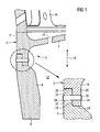
- Fig. 1 shows a detail of a cross section through a cover 2 for the reactor core of a boiling water reactor, wherein in the right half of the figure in the left half of the figure marked with the dashed circle detail is shown.
- the cover element 2 is arranged in the interior of a reactor pressure vessel, not shown here, and in its operating position closes the core area with the fuel elements therein upward.
- the cover element 2 comprises a core cover 3 with a spherically curved, flattened cover shell 4 and a support ring 6 of a substantially cylindrical shape connected to the cover shell 4.
- the support ring 6 is detachably mounted at its lower edge 8 on a core grid provided for receiving fuel elements.
- the core grid is not shown because the details of the attachment are of no interest here.
- the distance in the longitudinal direction 10 between the dome-shaped cover shell 4 and the core region located thereunder with the fuel elements is increased compared to a design without a support ring 6.
- the forming in the reactor pressure vessel during reactor operation water-vapor mixture can collect and even before it through not arranged in the core cover 3 through openings 14 in the upwardly adjoining standpipes one here further illustrated water-steam separator occurs.
- an annular connecting flange 17 is further integrally formed, on which a serving as a support for a steam dryer not shown here support structure 16 is attached.
- an angled downwardly bent cylindrical connecting ring 18 is formed, which has an annular shoulder 20 at its lower end.
- This shoulder 20 is adapted to a likewise annular, corresponding shoulder 22 at the upper edge of the support ring 6 such that viewed in cross-section forms a simple toothing.
- the two paragraphs 20, 22 each have the same height, so that both the inner bearing surfaces 24 and the height-offset outer bearing surfaces 26 of the support ring 6 and connecting ring 18 are flat on each other.
- the bearing surfaces 24, 26 each have an annular shape and are each in a horizontal plane.
- the grading is executed at right angles, such that even the vertically oriented, a cylindrical surface surface forming contact surfaces 28 of the two paragraphs 20, 22 are without gaps.
- the edges of the paragraphs 20, 22 may be slightly bevelled or rounded. In the exemplary embodiment, both paragraphs 20, 22 have the same width, so that the contact forces distribute evenly on the upper (outer) and on the lower (inner) annulus.
- a number of circumferentially distributed around the cylindrical structure around pin 30 is provided.
- Each of the bolts 30 sits snugly in a corresponding recess or bore 32 extending in the radial direction through the two paragraphs 20, 22 of the support ring 6 and connecting ring 18.
- the length of the respective bolt 30 is slightly larger than the given by the entire wall thickness in this area length of the bore 32. To secure the bolt 30 against displacement this is at the outer circular boundary edge of the bore 32 with the respective paragraph 20, 22 welded ( Securing seam 34).
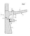
- the attachment of the core cover 3 on the support ring 6 is modified insofar as an elongated threaded bolt 36 through an associated recess 38 in the cover shell 4 of the core cover 3 passes through and is held at its lower end in a provided with an internal thread recess 42 in a mounting bracket 44 of the support ring 6.
- the mounting bracket 44 protruding into the cylinder interior is welded to the inner wall of the support ring 6.
- the mounting bracket 44 may also be forged to avoid welds.
- the threaded bolt 36 is secured by a nut 48. Similar to the previous embodiment, an additional securing of the threaded bolt 36 can be realized by welding the threaded bolt 36 with the core cover 3 or with the mounting bracket 44.
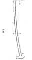
- the wall thickness of the cover shell 4 starting from its center outwardly to increase continuously. That is, in the vicinity of the cylindrical terminal ring 18, the thickness of the lid shell 4 is greater than in the middle. This can for example be realized in that the centers of the inner side 52 and the outer side 54 of the cover shell 4 associated radii along the central axis 56 are offset or arranged eccentrically. This results in the in Fig. 3 shown by dotted lines advantageous shape of the cover shell 4, which differs from the usual embodiment according to the solid lines.
Landscapes
- Physics & Mathematics (AREA)
- Engineering & Computer Science (AREA)
- Plasma & Fusion (AREA)
- General Engineering & Computer Science (AREA)
- High Energy & Nuclear Physics (AREA)
- Monitoring And Testing Of Nuclear Reactors (AREA)
- Structure Of Emergency Protection For Nuclear Reactors (AREA)
- Pressure Vessels And Lids Thereof (AREA)
Applications Claiming Priority (1)
| Application Number | Priority Date | Filing Date | Title |
|---|---|---|---|
| DE102005037589A DE102005037589B4 (de) | 2005-08-05 | 2005-08-05 | Abdeckelement für den Reaktorkern einer kerntechnischen Anlage sowie Kernreaktor |
Publications (3)
| Publication Number | Publication Date |
|---|---|
| EP1750284A2 EP1750284A2 (de) | 2007-02-07 |
| EP1750284A3 EP1750284A3 (de) | 2008-07-09 |
| EP1750284B1 true EP1750284B1 (de) | 2013-05-29 |
Family
ID=36940484
Family Applications (1)
| Application Number | Title | Priority Date | Filing Date |
|---|---|---|---|
| EP06012837.8A Not-in-force EP1750284B1 (de) | 2005-08-05 | 2006-06-22 | Abdeckelement für den Reaktorkern eines Siedewasserreaktors |
Country Status (5)
| Country | Link |
|---|---|
| US (1) | US7751522B2 (enExample) |
| EP (1) | EP1750284B1 (enExample) |
| JP (1) | JP5030503B2 (enExample) |
| DE (1) | DE102005037589B4 (enExample) |
| ES (1) | ES2425963T3 (enExample) |
Families Citing this family (2)
| Publication number | Priority date | Publication date | Assignee | Title |
|---|---|---|---|---|
| DE102013101461A1 (de) | 2013-02-14 | 2014-08-14 | Emitec Gesellschaft Für Emissionstechnologie Mbh | Abgasleitungsabschnitt zur Zufuhr von flüssigem Additiv |
| KR101653942B1 (ko) * | 2016-02-23 | 2016-09-02 | 문인득 | 원자로 증기 발생기의 하부 구조물 냉각장치 |
Citations (9)
| Publication number | Priority date | Publication date | Assignee | Title |
|---|---|---|---|---|
| GB1036388A (en) * | 1964-07-01 | 1966-07-20 | Rheinstahl Huettenwerke Ag | Improvements relating to pressure vessels |
| DE1564783A1 (de) * | 1965-12-17 | 1970-09-17 | Framatome Sa | Sicherheitsverschluss fuer einen Druckmedienreaktor |
| US3711371A (en) * | 1971-01-06 | 1973-01-16 | Consolidated Edison Co | Nuclear reactor vessel structure |
| US3717352A (en) * | 1969-04-26 | 1973-02-20 | Interatum Int Atomreaktorbau G | Seal for rotatable covers of nuclear reactors |
| US3744660A (en) * | 1970-12-30 | 1973-07-10 | Combustion Eng | Shield for nuclear reactor vessel |
| CH554585A (de) * | 1972-08-28 | 1974-09-30 | Siemens Ag | Kernreaktor mit einem reaktordruckbehaelter. |
| US4240561A (en) * | 1979-05-16 | 1980-12-23 | Chicago Bridge & Iron Company | Flanged connection for pressure vessel |
| JPS5770494A (en) * | 1980-10-22 | 1982-04-30 | Hitachi Ltd | Shraud |
| US5754612A (en) * | 1995-04-24 | 1998-05-19 | General Electric Company | Joint for interfacing steel head closure and prestressed concrete reactor vessel |
Family Cites Families (19)
| Publication number | Priority date | Publication date | Assignee | Title |
|---|---|---|---|---|
| US3318779A (en) * | 1965-06-09 | 1967-05-09 | Richard F Turner | Fuel element |
| US4192717A (en) * | 1974-12-06 | 1980-03-11 | Siempelkamp Giesserei Kg | Cover for a nuclear reactor pressure vessel |
| FR2309017A1 (fr) * | 1975-04-25 | 1976-11-19 | Westinghouse Electric Corp | Support de reacteur nucleaire |
| US4158605A (en) * | 1975-11-25 | 1979-06-19 | Westinghouse Electric Corp. | Nuclear core baffling apparatus |
| US4348356A (en) * | 1980-05-09 | 1982-09-07 | The United States Of America As Represented By The United States Department Of Energy | Reactor vessel support system |
| DE3027513A1 (de) * | 1980-07-19 | 1982-02-25 | Hochtemperatur-Reaktorbau GmbH, 5000 Köln | Abstuetzeinrichtung fuer den aus kugelfoermigen brennelementen aufgeschuetteten kern eines hochtemperaturreaktors |
| US4786461A (en) * | 1983-09-30 | 1988-11-22 | Westinghouse Electric Corp. | Reactor internals hold down spring |
| JPS62116292A (ja) * | 1985-11-15 | 1987-05-27 | 株式会社東芝 | 原子炉構造物の取付装置 |
| JPS62121391A (ja) * | 1985-11-22 | 1987-06-02 | 株式会社日立製作所 | 上部格子板 |
| JPS62126389A (ja) * | 1985-11-27 | 1987-06-08 | 株式会社日立製作所 | 原子炉内部構造物 |
| DE3615686A1 (de) * | 1986-05-09 | 1987-11-12 | Klein Schanzlin & Becker Ag | Kanalrad fuer kreiselpumpen |
| US4818476A (en) * | 1988-02-25 | 1989-04-04 | Westinghouse Electric Corp. | Reactor vessel stud thread protector |
| JP2945707B2 (ja) * | 1990-03-29 | 1999-09-06 | 株式会社東芝 | 原子炉圧力容器支持ペデスタルの据付方法 |
| US5538381A (en) * | 1994-06-16 | 1996-07-23 | General Electric Company | Mechanism for coupling a member to a circular hole in a metal plate |
| WO1998009294A1 (de) * | 1996-08-28 | 1998-03-05 | Siemens Aktiengesellschaft | Mantel zum umfassen eines reaktorkerns |
| DE19703226C1 (de) * | 1997-01-29 | 1998-06-18 | Siemens Ag | Halterung für Brennelemente und Verfahren zur Instandsetzung einer solchen Halterung |
| US6059378A (en) * | 1997-05-01 | 2000-05-09 | Impact Forge, Inc. | Taperlock axle apparatus and flange |
| US6055288A (en) * | 1998-07-24 | 2000-04-25 | Westinghouse Electric Company | Nuclear reactor vessel |
| US6546066B2 (en) * | 2001-08-02 | 2003-04-08 | Advent Engineering Services, Inc. | Integrated head assembly for a nuclear reactor |
-
2005
- 2005-08-05 DE DE102005037589A patent/DE102005037589B4/de not_active Expired - Fee Related
-
2006
- 2006-06-22 ES ES06012837T patent/ES2425963T3/es active Active
- 2006-06-22 EP EP06012837.8A patent/EP1750284B1/de not_active Not-in-force
- 2006-08-03 JP JP2006212257A patent/JP5030503B2/ja not_active Expired - Fee Related
- 2006-08-07 US US11/500,035 patent/US7751522B2/en not_active Expired - Fee Related
Patent Citations (9)
| Publication number | Priority date | Publication date | Assignee | Title |
|---|---|---|---|---|
| GB1036388A (en) * | 1964-07-01 | 1966-07-20 | Rheinstahl Huettenwerke Ag | Improvements relating to pressure vessels |
| DE1564783A1 (de) * | 1965-12-17 | 1970-09-17 | Framatome Sa | Sicherheitsverschluss fuer einen Druckmedienreaktor |
| US3717352A (en) * | 1969-04-26 | 1973-02-20 | Interatum Int Atomreaktorbau G | Seal for rotatable covers of nuclear reactors |
| US3744660A (en) * | 1970-12-30 | 1973-07-10 | Combustion Eng | Shield for nuclear reactor vessel |
| US3711371A (en) * | 1971-01-06 | 1973-01-16 | Consolidated Edison Co | Nuclear reactor vessel structure |
| CH554585A (de) * | 1972-08-28 | 1974-09-30 | Siemens Ag | Kernreaktor mit einem reaktordruckbehaelter. |
| US4240561A (en) * | 1979-05-16 | 1980-12-23 | Chicago Bridge & Iron Company | Flanged connection for pressure vessel |
| JPS5770494A (en) * | 1980-10-22 | 1982-04-30 | Hitachi Ltd | Shraud |
| US5754612A (en) * | 1995-04-24 | 1998-05-19 | General Electric Company | Joint for interfacing steel head closure and prestressed concrete reactor vessel |
Also Published As
| Publication number | Publication date |
|---|---|
| DE102005037589B4 (de) | 2009-02-05 |
| JP5030503B2 (ja) | 2012-09-19 |
| US7751522B2 (en) | 2010-07-06 |
| EP1750284A3 (de) | 2008-07-09 |
| ES2425963T3 (es) | 2013-10-18 |
| US20100124305A1 (en) | 2010-05-20 |
| JP2007047159A (ja) | 2007-02-22 |
| EP1750284A2 (de) | 2007-02-07 |
| DE102005037589A1 (de) | 2007-02-08 |
Similar Documents
| Publication | Publication Date | Title |
|---|---|---|
| DE102013109765B4 (de) | Fundamentanordnung für den Turm einer Windkraftanlage mit abnehmbaren Turmfundamentringen | |
| DE69612884T2 (de) | Federrastmechanismus | |
| EP2154367B1 (de) | Verfahren zur Montage einer Rotornabe an einer Rotorwelle einer Windenergieanlage und Windenergieanlage | |
| DE102011085947A1 (de) | Turmfußsektion einer Windenergieanlage | |
| CH699710B1 (de) | Rohrschelle. | |
| DE2647458A1 (de) | Anordnung zur kuehlung von befestigungsmitteln in fluessigkeitsgekuehlten kernreaktoren | |
| WO2018019832A1 (de) | Verbindungselement zum verbinden von turmabschnitten, turmabschnitt, turm, windenergieanlage sowie verfahren zum herstellen eines turmabschnitts und zum verbinden von turmabschnitten | |
| EP0560764B1 (de) | Brennelement oder steuerelement mit einer lösbaren verriegelung zwischen kasten und oberen oder unteren endteil des elementes | |
| DE2854155C2 (enExample) | ||
| DE2735450A1 (de) | Dampferzeuger fuer kernkraftwerke, insbesondere fuer druckwasserreaktoren | |
| DE69410215T2 (de) | Vorrichtung für schwingungsneutralisierendes Festsetzen von Wärmetauscherrohren und seine Verwendung | |
| DE102013108609A1 (de) | Kappensystem für Turbinenöffnungen | |
| EP1750284B1 (de) | Abdeckelement für den Reaktorkern eines Siedewasserreaktors | |
| DE69922321T2 (de) | Innere Struktur eines Kernreaktors mit Mittel zur Stabilisierung des Kühlmittelstromes | |
| DE69104567T2 (de) | Führungsrohreinsatz für Kernreaktor. | |
| DE2754462C3 (de) | Atomkernreaktor mit einem Druckbehälter | |
| DE69415467T2 (de) | Dampferzeuger mit radialer Haltevorrichtung für die Rohrbündelhülle und die Rohrabstandsplatten | |
| DE69703063T2 (de) | Druckgefässbodendurchdringung | |
| CH697715A2 (de) | Spannanordnung für Kernsprüh-Verteilerring-T-Behälter. | |
| WO2016203035A1 (de) | Windenergieanlagen-turm und windenergieanlage | |
| DE69623715T2 (de) | Brennstabbündelaufbau unter Benützung des Brennstoffkanals als tragendes Element sowie Verfahren zum Entnehmen eines Brennstabbündels aus dem Brennstoffkanal | |
| EP2549845A2 (de) | Schaltschrank für ein Pitchsystem | |
| DE202014010870U1 (de) | Rührwerkwelle eines Fermenters und Befestigungsverfahren von Rührarmen | |
| CH650352A5 (de) | Verfahren zum befestigen und entfernen eines neutronen absorbierenden stabes und einrichtung mit einem armstern zum aufnehmen eines stabes. | |
| DE2631408C2 (enExample) |
Legal Events
| Date | Code | Title | Description |
|---|---|---|---|
| PUAI | Public reference made under article 153(3) epc to a published international application that has entered the european phase |
Free format text: ORIGINAL CODE: 0009012 |
|
| AK | Designated contracting states |
Kind code of ref document: A2 Designated state(s): AT BE BG CH CY CZ DE DK EE ES FI FR GB GR HU IE IS IT LI LT LU LV MC NL PL PT RO SE SI SK TR |
|
| AX | Request for extension of the european patent |
Extension state: AL BA HR MK YU |
|
| RAP1 | Party data changed (applicant data changed or rights of an application transferred) |
Owner name: AREVA NP GMBH |
|
| PUAL | Search report despatched |
Free format text: ORIGINAL CODE: 0009013 |
|
| RAP1 | Party data changed (applicant data changed or rights of an application transferred) |
Owner name: AREVA NP GMBH |
|
| AK | Designated contracting states |
Kind code of ref document: A3 Designated state(s): AT BE BG CH CY CZ DE DK EE ES FI FR GB GR HU IE IS IT LI LT LU LV MC NL PL PT RO SE SI SK TR |
|
| AX | Request for extension of the european patent |
Extension state: AL BA HR MK RS |
|
| AKX | Designation fees paid | ||
| 17P | Request for examination filed |
Effective date: 20080729 |
|
| RBV | Designated contracting states (corrected) |
Designated state(s): CH DE ES FI LI SE |
|
| 17Q | First examination report despatched |
Effective date: 20090414 |
|
| GRAP | Despatch of communication of intention to grant a patent |
Free format text: ORIGINAL CODE: EPIDOSNIGR1 |
|
| GRAS | Grant fee paid |
Free format text: ORIGINAL CODE: EPIDOSNIGR3 |
|
| GRAA | (expected) grant |
Free format text: ORIGINAL CODE: 0009210 |
|
| AK | Designated contracting states |
Kind code of ref document: B1 Designated state(s): CH DE ES FI LI SE |
|
| REG | Reference to a national code |
Ref country code: CH Ref legal event code: EP |
|
| REG | Reference to a national code |
Ref country code: DE Ref legal event code: R096 Ref document number: 502006012896 Country of ref document: DE Effective date: 20130725 |
|
| REG | Reference to a national code |
Ref country code: CH Ref legal event code: NV Representative=s name: E. BLUM AND CO. AG PATENT- UND MARKENANWAELTE , CH Ref country code: CH Ref legal event code: PFA Owner name: AREVA GMBH, DE Free format text: FORMER OWNER: AREVA NP GMBH, DE |
|
| RAP2 | Party data changed (patent owner data changed or rights of a patent transferred) |
Owner name: AREVA GMBH |
|
| REG | Reference to a national code |
Ref country code: SE Ref legal event code: TRGR |
|
| REG | Reference to a national code |
Ref country code: DE Ref legal event code: R081 Ref document number: 502006012896 Country of ref document: DE Owner name: AREVA GMBH, DE Free format text: FORMER OWNER: AREVA NP GMBH, 91052 ERLANGEN, DE Effective date: 20130806 Ref country code: DE Ref legal event code: R081 Ref document number: 502006012896 Country of ref document: DE Owner name: AREVA GMBH, DE Free format text: FORMER OWNER: AREVA NP GMBH, 91052 ERLANGEN, DE Effective date: 20130603 |
|
| REG | Reference to a national code |
Ref country code: ES Ref legal event code: FG2A Ref document number: 2425963 Country of ref document: ES Kind code of ref document: T3 Effective date: 20131018 |
|
| PLBE | No opposition filed within time limit |
Free format text: ORIGINAL CODE: 0009261 |
|
| STAA | Information on the status of an ep patent application or granted ep patent |
Free format text: STATUS: NO OPPOSITION FILED WITHIN TIME LIMIT |
|
| 26N | No opposition filed |
Effective date: 20140303 |
|
| REG | Reference to a national code |
Ref country code: DE Ref legal event code: R097 Ref document number: 502006012896 Country of ref document: DE Effective date: 20140303 |
|
| PGFP | Annual fee paid to national office [announced via postgrant information from national office to epo] |
Ref country code: ES Payment date: 20160622 Year of fee payment: 11 Ref country code: CH Payment date: 20160621 Year of fee payment: 11 Ref country code: FI Payment date: 20160620 Year of fee payment: 11 |
|
| PGFP | Annual fee paid to national office [announced via postgrant information from national office to epo] |
Ref country code: SE Payment date: 20160621 Year of fee payment: 11 |
|
| PGFP | Annual fee paid to national office [announced via postgrant information from national office to epo] |
Ref country code: DE Payment date: 20160627 Year of fee payment: 11 |
|
| REG | Reference to a national code |
Ref country code: DE Ref legal event code: R119 Ref document number: 502006012896 Country of ref document: DE |
|
| REG | Reference to a national code |
Ref country code: SE Ref legal event code: EUG |
|
| PG25 | Lapsed in a contracting state [announced via postgrant information from national office to epo] |
Ref country code: FI Free format text: LAPSE BECAUSE OF NON-PAYMENT OF DUE FEES Effective date: 20170622 |
|
| REG | Reference to a national code |
Ref country code: CH Ref legal event code: PL |
|
| PG25 | Lapsed in a contracting state [announced via postgrant information from national office to epo] |
Ref country code: SE Free format text: LAPSE BECAUSE OF NON-PAYMENT OF DUE FEES Effective date: 20170623 |
|
| PG25 | Lapsed in a contracting state [announced via postgrant information from national office to epo] |
Ref country code: CH Free format text: LAPSE BECAUSE OF NON-PAYMENT OF DUE FEES Effective date: 20170630 Ref country code: LI Free format text: LAPSE BECAUSE OF NON-PAYMENT OF DUE FEES Effective date: 20170630 Ref country code: DE Free format text: LAPSE BECAUSE OF NON-PAYMENT OF DUE FEES Effective date: 20180103 |
|
| REG | Reference to a national code |
Ref country code: ES Ref legal event code: FD2A Effective date: 20181113 |
|
| PG25 | Lapsed in a contracting state [announced via postgrant information from national office to epo] |
Ref country code: ES Free format text: LAPSE BECAUSE OF NON-PAYMENT OF DUE FEES Effective date: 20170623 |