EP1750140A2 - Pulsradar - Google Patents
Pulsradar Download PDFInfo
- Publication number
- EP1750140A2 EP1750140A2 EP06015625A EP06015625A EP1750140A2 EP 1750140 A2 EP1750140 A2 EP 1750140A2 EP 06015625 A EP06015625 A EP 06015625A EP 06015625 A EP06015625 A EP 06015625A EP 1750140 A2 EP1750140 A2 EP 1750140A2
- Authority
- EP
- European Patent Office
- Prior art keywords
- pulse
- reception
- transmission
- circuit
- cycle
- Prior art date
- Legal status (The legal status is an assumption and is not a legal conclusion. Google has not performed a legal analysis and makes no representation as to the accuracy of the status listed.)
- Withdrawn
Links
- 230000005540 biological transmission Effects 0.000 claims abstract description 135
- 230000000737 periodic effect Effects 0.000 claims abstract description 3
- 230000001360 synchronised effect Effects 0.000 claims description 8
- 230000008859 change Effects 0.000 claims description 6
- 239000000284 extract Substances 0.000 abstract description 6
- 238000001514 detection method Methods 0.000 description 9
- 238000010586 diagram Methods 0.000 description 6
- 238000006243 chemical reaction Methods 0.000 description 5
- 230000006872 improvement Effects 0.000 description 3
- 238000012545 processing Methods 0.000 description 3
- 238000000605 extraction Methods 0.000 description 2
- 238000000034 method Methods 0.000 description 2
- 230000005855 radiation Effects 0.000 description 2
- 230000009467 reduction Effects 0.000 description 2
- 238000007796 conventional method Methods 0.000 description 1
- 238000013461 design Methods 0.000 description 1
- 238000012986 modification Methods 0.000 description 1
- 230000004048 modification Effects 0.000 description 1
- 238000002360 preparation method Methods 0.000 description 1
Images


Classifications
-
- G—PHYSICS
- G01—MEASURING; TESTING
- G01S—RADIO DIRECTION-FINDING; RADIO NAVIGATION; DETERMINING DISTANCE OR VELOCITY BY USE OF RADIO WAVES; LOCATING OR PRESENCE-DETECTING BY USE OF THE REFLECTION OR RERADIATION OF RADIO WAVES; ANALOGOUS ARRANGEMENTS USING OTHER WAVES
- G01S13/00—Systems using the reflection or reradiation of radio waves, e.g. radar systems; Analogous systems using reflection or reradiation of waves whose nature or wavelength is irrelevant or unspecified
- G01S13/02—Systems using reflection of radio waves, e.g. primary radar systems; Analogous systems
- G01S13/06—Systems determining position data of a target
- G01S13/08—Systems for measuring distance only
- G01S13/10—Systems for measuring distance only using transmission of interrupted, pulse modulated waves
- G01S13/22—Systems for measuring distance only using transmission of interrupted, pulse modulated waves using irregular pulse repetition frequency
- G01S13/227—Systems for measuring distance only using transmission of interrupted, pulse modulated waves using irregular pulse repetition frequency with repetitive trains of uniform pulse sequences, each sequence having a different pulse repetition frequency
-
- G—PHYSICS
- G01—MEASURING; TESTING
- G01S—RADIO DIRECTION-FINDING; RADIO NAVIGATION; DETERMINING DISTANCE OR VELOCITY BY USE OF RADIO WAVES; LOCATING OR PRESENCE-DETECTING BY USE OF THE REFLECTION OR RERADIATION OF RADIO WAVES; ANALOGOUS ARRANGEMENTS USING OTHER WAVES
- G01S13/00—Systems using the reflection or reradiation of radio waves, e.g. radar systems; Analogous systems using reflection or reradiation of waves whose nature or wavelength is irrelevant or unspecified
- G01S13/02—Systems using reflection of radio waves, e.g. primary radar systems; Analogous systems
- G01S13/06—Systems determining position data of a target
- G01S13/08—Systems for measuring distance only
- G01S13/10—Systems for measuring distance only using transmission of interrupted, pulse modulated waves
- G01S13/103—Systems for measuring distance only using transmission of interrupted, pulse modulated waves particularities of the measurement of the distance
-
- G—PHYSICS
- G01—MEASURING; TESTING
- G01S—RADIO DIRECTION-FINDING; RADIO NAVIGATION; DETERMINING DISTANCE OR VELOCITY BY USE OF RADIO WAVES; LOCATING OR PRESENCE-DETECTING BY USE OF THE REFLECTION OR RERADIATION OF RADIO WAVES; ANALOGOUS ARRANGEMENTS USING OTHER WAVES
- G01S7/00—Details of systems according to groups G01S13/00, G01S15/00, G01S17/00
- G01S7/02—Details of systems according to groups G01S13/00, G01S15/00, G01S17/00 of systems according to group G01S13/00
- G01S7/28—Details of pulse systems
- G01S7/285—Receivers
- G01S7/288—Coherent receivers
-
- G—PHYSICS
- G01—MEASURING; TESTING
- G01S—RADIO DIRECTION-FINDING; RADIO NAVIGATION; DETERMINING DISTANCE OR VELOCITY BY USE OF RADIO WAVES; LOCATING OR PRESENCE-DETECTING BY USE OF THE REFLECTION OR RERADIATION OF RADIO WAVES; ANALOGOUS ARRANGEMENTS USING OTHER WAVES
- G01S7/00—Details of systems according to groups G01S13/00, G01S15/00, G01S17/00
- G01S7/02—Details of systems according to groups G01S13/00, G01S15/00, G01S17/00 of systems according to group G01S13/00
- G01S7/28—Details of pulse systems
- G01S7/285—Receivers
- G01S7/292—Extracting wanted echo-signals
- G01S7/2923—Extracting wanted echo-signals based on data belonging to a number of consecutive radar periods
-
- H—ELECTRICITY
- H03—ELECTRONIC CIRCUITRY
- H03D—DEMODULATION OR TRANSFERENCE OF MODULATION FROM ONE CARRIER TO ANOTHER
- H03D7/00—Transference of modulation from one carrier to another, e.g. frequency-changing
- H03D7/14—Balanced arrangements
- H03D7/1408—Balanced arrangements with diodes
-
- G—PHYSICS
- G01—MEASURING; TESTING
- G01S—RADIO DIRECTION-FINDING; RADIO NAVIGATION; DETERMINING DISTANCE OR VELOCITY BY USE OF RADIO WAVES; LOCATING OR PRESENCE-DETECTING BY USE OF THE REFLECTION OR RERADIATION OF RADIO WAVES; ANALOGOUS ARRANGEMENTS USING OTHER WAVES
- G01S13/00—Systems using the reflection or reradiation of radio waves, e.g. radar systems; Analogous systems using reflection or reradiation of waves whose nature or wavelength is irrelevant or unspecified
- G01S13/02—Systems using reflection of radio waves, e.g. primary radar systems; Analogous systems
- G01S13/06—Systems determining position data of a target
- G01S13/08—Systems for measuring distance only
- G01S13/10—Systems for measuring distance only using transmission of interrupted, pulse modulated waves
- G01S13/18—Systems for measuring distance only using transmission of interrupted, pulse modulated waves wherein range gates are used
-
- G—PHYSICS
- G01—MEASURING; TESTING
- G01S—RADIO DIRECTION-FINDING; RADIO NAVIGATION; DETERMINING DISTANCE OR VELOCITY BY USE OF RADIO WAVES; LOCATING OR PRESENCE-DETECTING BY USE OF THE REFLECTION OR RERADIATION OF RADIO WAVES; ANALOGOUS ARRANGEMENTS USING OTHER WAVES
- G01S13/00—Systems using the reflection or reradiation of radio waves, e.g. radar systems; Analogous systems using reflection or reradiation of waves whose nature or wavelength is irrelevant or unspecified
- G01S13/88—Radar or analogous systems specially adapted for specific applications
- G01S13/93—Radar or analogous systems specially adapted for specific applications for anti-collision purposes
- G01S13/931—Radar or analogous systems specially adapted for specific applications for anti-collision purposes of land vehicles
Definitions
- the present invention relates to a pulse radar system using a millimeter wave band or a quasi-millimeter wave band, and particularly to a pulse radar system having improvements in distance resolution with respect to a reflective wave from objects in a short distance.
- a pulse radar system is used with the purpose of collision avoidance or auto clews.
- the round-trip distance to an object can be found by multiplying the time that elapses between the radiation of a transmission pulse and the receipt of a reception pulse wave reflected from the object, by light velocity. Consequently, the pulse radar system is intended for calculating the distance to the object by measuring the time that elapses between the radiation of the transmission pulse wave and the receipt of the reception pulse wave from the object.
- the transmission pulse wave is radiated, followed by preparation for receiving the reception pulse wave reflected from the object in a short distance.
- the pulse radar system with the purpose of collision avoidance or auto clews demands exact detection of the positions of objects in a wide range of from tens of centimeters to tens of meters.
- the pulse width of a transmission pulse wave is reduced so as to eliminate overlapping between reception pulse waves from the different objects, thereby increasing distance resolution between those objects (for example, refer to Japanese Unexamined Patent Publication No. 6-249943 ).
- a pulse width of 3 nsec or less is needed for detecting two obstacles one meter apart. That is, transmission pulses are reflected from the two obstacles, respectively, so that the time between these reflected waves is 3 nsec or less. It is therefore necessary to perform sequentially signal processing of their respective reception pulses (for example, when performing signal processing of A/D (analog-digital)'conversion) in time intervals as short as 3 nsec. This requires a high-speed circuit, and increases signal processing circuit load.
- a reception pulse is extracted in synchronization with a gate pulse having a cycle which is a rational multiple of a cycle of a transmission pulse and is different from the cycle of the transmission pulse.
- a pulse radar system including: a pulse output circuit outputting a periodic transmission pulse and a gate pulse, the gate pulse having a cycle which is a rational multiple of a cycle of the transmission pulse and is different from the cycle of the transmission pulse; a transmission circuit generating a transmission pulse wave based on a transmission pulse from the pulse output circuit, and outputting the transmission pulse wave generated; a transmission antenna radiating a transmission pulse wave from the transmission circuit; a reception antenna receiving a reception pulse wave, the reception pulse wave being radiated from the transmission antenna as a transmission pulse wave and reflected from an object; a reception circuit demodulating the reception pulse wave from the reception antenna and outputting a reception pulse; and an extracting circuit extracting a reception pulse, which is synchronized with a gate pulse from the pulse output circuit, from among reception pulses from the reception circuit, and outputting the reception pulse extracted.
- a time base can be expanded to improve distance resolution between objects without requiring speed-up of the reception circuit.
- the pulse output circuit can change the ratio between a cycle of the transmission pulse and a cycle of the gate pulse.
- This provides a variable rate of time base expansion, making it possible to select freely distance resolution between objects.
- the pulse output circuit can change a relative phase between the transmission pulse and the gate pulse.
- the time base can be shifted by changing the ratio between a cycle of the transmission pulse and a cycle of the gate pulse, and by changing the relative phase between the transmission pulse and the gate pulse. It is therefore possible to extract a reception pulse in a specific position, and select freely a detecting position of the objects on the time base.
- the pulse radar system is further provided with a distance calculating circuit calculating a distance to the object, based on an elapsed time from when a transmission pulse which immediately precedes a reception pulse extracted by the extracting circuit is outputted from the pulse output circuit until the reception pulse is outputted from the extracting circuit.
- the pulse radar system is further provided with a distance calculating circuit calculating a distance to the object based on an elapsed time, a phase of a transmission pulse outputted from the pulse output circuit and a cycle of the transmission pulse at the time when the reception pulse is outputted from the extracting circuit, the elapsed time being from when a transmission pulse is outputted from the pulse output circuit until a reception pulse is outputted from the extracting circuit.
- the extracting circuit is configured as a single balanced mixer taking in the gate pulse from the pulse output circuit as a balanced input, and finding a product of the gate pulse and the reception pulse from the reception circuit.
- the extracting circuit is configured as a double balanced mixer taking in both the gate pulse from the pulse output circuit and the reception pulse from the reception circuit as balanced inputs, and finding a product of the gate pulse and the reception pulse from the reception circuit.
- the embodiment of the present invention provides the pulse radar system capable of improving distance resolution between objects without requiring speed-up of the reception circuit.
- FIG. 1 is a block diagram illustrating an example of an embodiment of a pulse radar system according to the present invention.
- reference numeral 12 designates a pulse output circuit that outputs a transmission pulse of a predetermined cycle and a gate pulse having a cycle which is a rational multiple of a cycle of a transmission pulse and is different from the cycle of the transmission pulse.
- Reference numeral 13 designates an oscillator that oscillates in a modulation frequency.
- Reference numeral 14 designates a modulation circuit that generates a transmission pulse wave based on a transmission pulse.
- Reference numeral 15 designates a transmission antenna that radiates a transmission pulse wave.
- Reference numeral 21 designates a reception antenna that receives a reception pulse wave from an object.
- Reference numeral 22 designates a low noise amplifier that amplifies a reception pulse wave.
- Reference numeral 23 designates a demodulation circuit that demodulates a reception pulse wave.
- Reference numeral 24 designates an IF (intermediate frequency) amplifier that amplifies a reception pulse outputted from the demodulation circuit.
- Reference numeral 25 designates an extracting circuit that extracts a reception pulse synchronizing with a gate pulse among reception pulses.
- Reference numeral 26 designates an A/D conversion circuit that performs A/D (analog-digital) conversion of a reception pulse.
- Reference numeral 27 designates a distance calculating circuit that calculates the distance to an object.
- a transmission circuit includes the oscillator 13 and the modulation circuit 14.
- a reception circuit includes the low noise amplifier 22, the oscillator 13, the demodulation circuit 23, and the IF amplifier 24.
- the pulse output circuit 12 generates a transmission pulse at predetermined generation intervals. It is preferable that the generation intervals of the transmission pulse is set to be longer than the round-trip wave propagation time corresponding to a maximum detection distance of the pulse radar system 100.
- the pulse output circuit 12 outputs a gate pulse having a cycle which is a rational multiple of a cycle of a transmission pulse and is different from the cycle of the transmission pulse.
- the gate pulse is inputted to the extracting circuit 25 to be described later.
- the pulse output circuit 12 can change the ratio between a cycle of a transmission pulse and a cycle of a gate pulse, and also change the relative phase between the transmission pulse and the gate pulse. Further, the pulse output circuit 12 outputs a synchronized pulse that synchronizes with a transmission pulse, so that it is used as a start trigger when the distance to an object is calculated on the distance calculating circuit 27 to be described later.
- the modulation circuit 14 outputs a transmission pulse wave by mixing a transmission pulse from the pulse outputting circuit 12 and a modulation wave from the oscillator 13.
- the transmission antenna 15 radiates a transmission pulse wave from the modulation circuit 14.
- the transmission antenna 15 may be made up of a plurality of antennas.
- the configuration of a receiving system of the pulse radar system 100 will be described with reference to Figure 1.
- the reception antenna 21 receives a reception pulse wave reflected from an object.
- the reception antenna 21 may also be made up of a plurality of antennas. Alternatively, a transmitter-receiver antenna may be used.
- the demodulation circuit 23 demodulates a reception pulse wave amplified by the low noise amplifier 22, and then outputs a reception pulse.
- a detection mode that can be realized by a usual technique of synchronous detection, and asynchronous detection such as envelope demodulation.
- the oscillator 13 generates local signals in a frequency band used in the pulse radar system 100, and the synchronous detection is performed based on the local signals generated.
- the extracting circuit 25 extracts a reception pulse that synchronizes with a gate pulse from the pulse output circuit 12, among reception pulses demodulated by the demodulation circuit 23 and then amplified by the IF amplifier 24.
- the extracting circuit 25 is configured as a single balanced mixer taking in a gate pulse from the pulse output circuit 12 as a balanced input. More preferably, the extracting circuit 25 is configured as a double balanced mixer taking in both a gate pulse from the pulse output circuit 12 and a reception pulse from the demodulation circuit 23 as balanced inputs.
- the single balanced mixer can prevent signal leakage of a gate pulse, as described later.
- the double balanced mixer can prevent signal leakage of a gate pulse and a reception pulse, as described later.
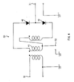
- reference numeral 30 designates an input port, to which a gate pulse is inputted.
- Reference numeral 31 designates an input port, to which a reception pulse from the demodulation circuit 23 is inputted.
- Reference numeral 32 designates an output port that outputs a reception pulse to the timing of a gate pulse.
- Reference numeral 41 designates a toroidal core that induces current by an input of a gate pulse.
- Reference numerals 42 and 43 are diodes that switch electrical continuity by an input of a gate pulse.
- the diodes 42 and 43 establish electrical continuity by an input of a gate pulse to the input port 30, so that a reception pulse synchronizing with a gate pulse among reception pulses inputted to the input port 31 can be outputted from the output port 32. That is, the single balanced mixer 50 finds the product of the gate pulse to the input port 30 and the reception pulse to the input port 31, and from among reception pulses inputted to the input port 31, extracts a reception pulse synchronizing with the gate pulse inputted to the input port 30, and then outputs the reception pulse from the output port 32.
- the output port 32 corresponds to a middle point of the toroidal core 41, so that the potential of a gate pulse inputted to the input port 30 causes no potential in the output port 32. Therefore, in the single balanced mixer 50, the gate pulse can be balanced so as to prevent signal leakage of the gate pulse to the output port 32. This improves the accuracy of detecting objects.
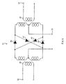
- reference numeral 33 designates an input port, to which a gate pulse is inputted.
- Reference numeral 34 designates an input port, to which a reception pulse from the demodulation circuit 23 is inputted.
- Reference numeral 35 designates an output port that outputs a reception pulse to the timing of a gate pulse.
- Reference numeral 44 designates a toroidal core that induces current by an input of a gate pulse.
- Reference numeral 45 designates a toroidal core that induces current by an input of a reception pulse.
- Reference numerals 46 to 49 are diodes that perform switching of an input of a gate pulse.
- the double balanced mixer 51 causes the output port 35 to generate an output only when a gate pulse inputted to the input port 33 synchronizes with a reception pulse inputted to the input port 34.
- the double balanced mixer 51 finds the product of the gate pulse to the input port 33 and the reception pulse to the input port 34, and from among reception pulses inputted to the input port 34, extracts a reception pulse synchronized with the gate pulse inputted to the input port 33, and then outputs the reception pulse from the output port 35.
- the output port 35 corresponds to a middle point of the toroidal cores 44 and 45, so that neither the gate pulse inputted to the input port 33 nor the reception pulse inputted to the input port 34 causes a potential in the input port 33. Therefore, in the double balanced mixer 51, both of the gate pulse and the reception pulse can be balanced so as to prevent signal leakage of the gate pulse and the reception pulse to the output port 35. This further improves the accuracy of detecting objects.
- the distance calculating circuit 27 shown in Fig. 1 calculates the distance from the pulse radar system 100 to an object, based on a reception pulse that is outputted from the extracting circuit 25 and subjected to A/D conversion by the A/D conversion circuit 26, and on a start trigger from the pulse output circuit 12.
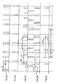
- Figs. 2A, 2B, 2C, 2D and 2E show examples of the timings of signal waveforms at the points A, B, C, D, and E in Fig. 1, respectively.
- the pulse widths of the respective signals are omitted, and the solid lines indicate the original signals, and the broken lines indicate signals which are obtained by changing the phase and the ratio of a transmission pulse and a gate pulse, respectively.
- like parts are identified by the same reference numerals as in Fig. 1.
- Fig. 2A indicates a transmission pulse that the pulse output circuit 12 outputs to the modulation circuit 14.
- the sending intervals of the transmission pulse is set to be longer than the round-trip propagation time corresponding to the maximum detection distance of the pulse radar system 100, as described above.
- the pulse width of the transmission pulse is shorter than the time corresponding to the distance resolution between objects.
- Fig. 2B indicates a start trigger that the pulse output circuit 12 outputs to the distance calculating circuit 27. This start trigger is synchronized with the transmission pulse. In the embodiment shown in Figs. 2A to 2E, it is adapted to output the start trigger having the same cycle as the transmission pulse as shown in Fig. 2A.
- Fig. 2C indicates reception pulses outputted from the demodulation circuit 23. Since these reception pulses are ones outputted from the pulse radar system 100 and reflected from the objects and then received, they are outputted with a delay with respect to the timing of the transmission pulse in Fig. 2A.
- the configuration in Fig. 2A to 2E illustrates a case where there are two objects. For ease in understanding, the reception pulse from the object closer to the pulse radar system 100 is plotted downward as viewed in the drawings, and the reception pulse from the remote object is plotted upward.
- Fig. 2D indicates a gate pulse outputted from the pulse output circuit 12 to the extracting circuit 25.
- the gate pulse has a cycle which is a rational multiple of a cycle of a transmission pulse shown in Fig. 2A and is different from the cycle of the transmission pulse.
- a cycle of the transmission pulse is set to four in number
- a cycle of the gate pulse is set to three in number. That is, during the time elapsed from the initial synchronization between the transmission pulse and the gate pulse until the next synchronization, there are three outputs of the transmission pulse, and four outputs of the gate pulse.
- Fig. 2E indicates reception pulses extracted by and outputted from the extracting circuit 25.
- reception pulses outputted from the demodulation circuit 23 may contain ones synchronizing with the gate pulse. Therefore, the extracting circuit 25 employs the balanced mixer as described above, to finds the product of the gate pulse in Fig. 2D and the reception pulses in Fig. 2C, so that only the reception pulse synchronizing with the gate pulse can be extracted periodically. By extracting the reception pulse in this manner, a cycle of the reception pulse can be expanded from a cycle B1 in Fig. 2C to a cycle b1 in Fig. 2E.
- a time difference between the reception pulses from the two objects can also be expanded from a time difference A to a time difference a1.
- the time base can be expanded to improve distance resolution by extracting the reception pulse synchronizing with the gate pulse, without requiring speed-up of the reception circuit.
- the ratio between the transmission pulse shown in Fig. 2A and the gate pulse shown in Fig. 2D is 4 to 3. Therefore, letting a cycle of the transmission pulse in Fig. 2A be B1, a cycle b1 of the reception pulse in Fig. 2E corresponds to expansion that is equivalent to three times a cycle B1. A time difference a1 between the reception pulses from the two objects can also be expanded to three times a time difference A.
- the ratio between a cycle B1 of the transmission pulse and a cycle G1 of the gate pulse is 4 to 3 (the ratio between a cycle of the transmission pulse and a cycle of the gate pulse is 3/4, that is 33%).
- a cycle of the reception pulse and the time difference between reception pulses from the two objects can be expanded to ⁇ times the original signal, respectively.
- a cycle of the transmission pulse in Fig. 2A is shifted from a cycle B1 to a cycle B2, and the phase of the transmission pulse is shifted by the amount of a time difference t ⁇ 1 when phase is expressed in terms of time; and a cycle of the gate pulse in Fig. 2D is shifted from a cycle G1 to a cycle G2, and the phase of the gate pulse is shifted by the amount of a time difference t ⁇ 2 when phase is expressed in terms of time.
- a cycle of the reception pulse can be expanded from a cycle B2 in Fig. 2C to a cycle b2 in Fig. 2E.
- the time difference between the reception pulses from the two objects can also be expanded from the time difference A to a time difference a2.
- a cycle B2 of the reception pulse is determined by the ratio between the transmission pulse shown in Fig. 2A and a cycle of the gate pulse shown in Fig. 2D. Therefore, the rate of time base expansion is variable by changing the ratio between a cycle of the transmission pulse and a cycle of the gate pulse. Hence, the distance resolution between the objects can be selected freely.
- either one of the reception pulses shown in Fig. 2C can be extracted at a different position from that before changing the phase, so that the time base can be shifted. This enables extraction of the reception pulse at a specific position, and free selection of the detection position of the objects on the time base.
- the time base of the specific position can be expanded and the distance resolution can be selected freely, and the detection position of the objects on the time base can be selected freely by shifting the time base while maintaining the selected distance resolution, and then extracting the reception pulse at the specific position.
- the ratio between a cycle of the transmission pulse and a cycle of the gate pulse can be changed within the pulse output circuit 12.
- the relative phase between the transmission pulse and the gate pulse can be changed within the pulse output circuit 12.
- the ratio between a cycle of the transmission pulse and a cycle of the gate pulse can also be changed, for example, by disposing a frequency multiplier (not shown) and a frequency divider (not shown) on the exterior of the pulse output circuit 12 so as to input either the transmission pulse or the gate pulse to the frequency multiplier and the frequency divider.
- the relative phase between the transmission pulse and the gate pulse can also be changed, for example, by disposing a delay circuit (not shown) on the exterior of the pulse output circuit 12 so as to input either the transmission pulse or the gate pulse to the delay circuit.
- the distance calculating circuit 27 calculates a distance to the object based on an elapsed time (a time difference ⁇ t) from when a transmission pulse immediately before a reception pulse extracted by the extracting circuit 25 is outputted from the pulse output circuit 12 until the reception pulse is outputted from the extracting circuit 25.
- This time corresponds to a round-trip propagation time t of a transmission pulse wave sent from the pulse radar system 100.
- the start trigger shown in Fig. 2B is sequentially updated and stored in a memory (not shown) on the distance calculating circuit 27.
- a reception pulse is outputted from the extracting circuit 25
- a time difference ⁇ t between the timing of the start trigger stored in the memory and the timing of the output of the reception pulse is measured and converted into a distance to the objects.
- the distance to the objects can be calculated by multiplying the time difference ⁇ t by light velocity and then dividing by 2.
- the time taken to acquire the reception pulse outputted from the extracting circuit 25 may be compensated within the distance calculating circuit 27, in consideration of delay time on the transmission circuit and the reception circuit within the pulse radar system 100.
- Figs. 3A, 3B, 3C, 3D and 3E show examples of the timings of signal waveforms at the points A, B, C, D, and E in Fig. 1, respectively.
- the pulse widths of the respective signals are omitted, and the solid lines indicate the original signals, and the broken lines indicate signals which are obtained by changing the phases and the ratio of a transmission pulse and a gate pulse, respectively.
- like parts are identified by the same reference numerals as in Fig. 1.
- the signals used in this embodiment are the same as those described with reference to Figs.
- the operation of the distance calculating circuit 27 is different from, and the operation of the extracting circuit 25 is the same as the operation described with reference to Figs. 2A to 2E. For this reason, only the operation of the distance calculating circuit 27 will be described below.
- the start trigger shown in Fig. 3B is synchronized with a transmission pulse.
- a start trigger of a cycle that is four times a transmission pulse shown in Fig. 3A is outputted from the pulse output circuit 12.
- a cycle of the start trigger may be any times a cycle of the transmission pulse, as far as it is different from a cycle of the transmission pulse.
- a time difference ⁇ t measured with the distance calculating circuit 27 is different from a round-trip propagation time t to be measured originally.
- the time difference ⁇ t is measured depending on the number of pulses of the transmission pulse that can be contained from the timing of the start trigger shown in Fig. 3B until the timing for extracting the reception pulse shown in Fig. 3E, and on the shift amount of the phase of the transmission pulse during that time. This enables the distance calculating circuit 27 to calculate the distance to the objects, based on an elapsed time (a time difference ⁇ t) from when the transmission pulse shown in Fig.
- 3A is outputted from the pulse output circuit 12 until the reception pulse shown in Fig. 3E is outputted from the extracting circuit 25, and based on the phase of the transmission pulse outputted from the pulse output circuit 12, and on a cycle B2 of the transmission pulse when the extracting circuit 25 outputs the reception pulse.
- information about the shift amount of the phase of the transmission pulse and a cycle of the transmission pulse are separately inputted from the pulse output circuit 12 to the distance calculating circuit 27.
- the start trigger shown in Fig. 3B is sequentially updated and stored in a memory (not shown) on the distance calculating circuit 27.
- a time difference ⁇ t between the timing of the start trigger stored in the memory and the timing of the output of the reception pulse is measured.
- a round-trip propagation time t can be calculated on the distance calculating circuit 27 in the following manner. That is, a time difference t ⁇ 1, which is obtained by converting the shift amount of the phase of the transmission pulse into time, is subtracted from a time difference ⁇ t, and then divided by a cycle B2 of the transmission pulse. The resulting remainder is the round-trip propagation time t.
- the distance to the objects can be calculated by multiplying the time difference ⁇ t by light velocity and then dividing by 2.
- the time taken to acquire the reception pulse outputted from the extracting circuit 25 may be compensated within the distance calculating circuit 27, in consideration of delay time on the transmission circuit and the reception circuit within the pulse radar system 100.
- the pulse radar system of the present invention is applicable to on vehicle equipments with the purpose of collision avoidance or auto clews, and is also usable as a stationary pulse radar system.
Landscapes
- Engineering & Computer Science (AREA)
- Radar, Positioning & Navigation (AREA)
- Remote Sensing (AREA)
- Computer Networks & Wireless Communication (AREA)
- Physics & Mathematics (AREA)
- General Physics & Mathematics (AREA)
- Power Engineering (AREA)
- Radar Systems Or Details Thereof (AREA)
Applications Claiming Priority (1)
| Application Number | Priority Date | Filing Date | Title |
|---|---|---|---|
| JP2005218449A JP2007033287A (ja) | 2005-07-28 | 2005-07-28 | パルス波レーダー装置 |
Publications (2)
| Publication Number | Publication Date |
|---|---|
| EP1750140A2 true EP1750140A2 (de) | 2007-02-07 |
| EP1750140A3 EP1750140A3 (de) | 2008-07-30 |
Family
ID=37415337
Family Applications (1)
| Application Number | Title | Priority Date | Filing Date |
|---|---|---|---|
| EP06015625A Withdrawn EP1750140A3 (de) | 2005-07-28 | 2006-07-26 | Pulsradar |
Country Status (3)
| Country | Link |
|---|---|
| US (1) | US7498975B2 (de) |
| EP (1) | EP1750140A3 (de) |
| JP (1) | JP2007033287A (de) |
Cited By (1)
| Publication number | Priority date | Publication date | Assignee | Title |
|---|---|---|---|---|
| EP2159597A3 (de) * | 2008-09-02 | 2014-03-05 | Preco Electronics, Inc. | Gepulstes Radar mit verbesserter Nahbereichsauflösung |
Families Citing this family (8)
| Publication number | Priority date | Publication date | Assignee | Title |
|---|---|---|---|---|
| JP4922098B2 (ja) * | 2007-08-17 | 2012-04-25 | 富士通株式会社 | 超広帯域レーダ装置及び広帯域レーダ装置の信号処理方法 |
| US8914342B2 (en) * | 2009-08-12 | 2014-12-16 | Yahoo! Inc. | Personal data platform |
| KR101083011B1 (ko) | 2010-05-11 | 2011-11-15 | 국방과학연구소 | 펄스 발생기 |
| KR20120064532A (ko) * | 2010-12-09 | 2012-06-19 | 한국전자통신연구원 | 펄스레이더 수신기 |
| KR20120065652A (ko) * | 2010-12-13 | 2012-06-21 | 한국전자통신연구원 | 레이더 센서용 rf 송수신기 |
| JP6105473B2 (ja) * | 2011-08-12 | 2017-03-29 | パナソニック株式会社 | レーダ装置 |
| US10641883B2 (en) * | 2016-08-31 | 2020-05-05 | Electronics And Telecommunications Research Institute | Pulse radar device and operating method thereof |
| US11067678B2 (en) * | 2017-07-20 | 2021-07-20 | Electronics And Telecommunications Research Institute | Radar device using delay |
Family Cites Families (21)
| Publication number | Priority date | Publication date | Assignee | Title |
|---|---|---|---|---|
| US2897490A (en) * | 1952-12-11 | 1959-07-28 | Philco Corp | Bandwidth compression system |
| US4161732A (en) * | 1976-11-12 | 1979-07-17 | Westinghouse Electric Corp. | Gated pulse compression radar |
| US4274095A (en) * | 1979-03-21 | 1981-06-16 | The United States Of America As Represented By The Secretary Of The Navy | Radar video converter |
| JPS61192131A (ja) * | 1985-02-20 | 1986-08-26 | Matsushita Electric Ind Co Ltd | チユ−ナ |
| US4727596A (en) * | 1986-07-16 | 1988-02-23 | Aubrey Jaffer | High dynamic range mixer |
| JPH0736492B2 (ja) * | 1986-12-11 | 1995-04-19 | 株式会社村田製作所 | ダブルバランスドミキサにおけるダイオ−ドの接続構造 |
| JPH03138576A (ja) | 1989-10-25 | 1991-06-12 | Nippon Mining Co Ltd | 電界効果トランジスタの評価方法 |
| JPH05327354A (ja) * | 1992-05-15 | 1993-12-10 | Hitachi Ltd | シングルバランスドミキサ回路 |
| JPH06249943A (ja) | 1993-02-26 | 1994-09-09 | Toei Denki Kogyo Kk | ヘリコプター衝突防止レーダ装置 |
| US5543799A (en) * | 1994-09-02 | 1996-08-06 | Zircon Corporation | Swept range gate radar system for detection of nearby objects |
| US5754144A (en) * | 1996-07-19 | 1998-05-19 | The Regents Of The University Of California | Ultra-wideband horn antenna with abrupt radiator |
| JP3639056B2 (ja) | 1996-08-16 | 2005-04-13 | 富士通株式会社 | レーダ装置の故障判別装置 |
| JP3820647B2 (ja) * | 1996-09-30 | 2006-09-13 | 日産自動車株式会社 | エンジンのトルクダウン制御装置 |
| US6122602A (en) | 1997-05-02 | 2000-09-19 | Endress + Hauser Gmbh + Co. | Method and arrangement for electromagnetic wave distance measurement by the pulse transit time method |
| AU8572298A (en) * | 1997-07-18 | 1999-02-10 | Kohler Company | Bathroom fixture using fluid interface radar sensor |
| US5994965A (en) | 1998-04-03 | 1999-11-30 | Cbs Corporation | Silicon carbide high frequency high power amplifier |
| JP3433718B2 (ja) | 2000-03-17 | 2003-08-04 | オムロン株式会社 | 距離検出装置 |
| US6873044B2 (en) | 2000-09-11 | 2005-03-29 | Xytrans, Inc. | Microwave monolithic integrated circuit package |
| JP2002311153A (ja) | 2001-04-12 | 2002-10-23 | Kanagawa Prefecture | 電波式生存者探査装置 |
| JP2004080865A (ja) | 2002-08-12 | 2004-03-11 | Nissan Motor Co Ltd | 半導体の異常診断回路 |
| US7002511B1 (en) | 2005-03-02 | 2006-02-21 | Xytrans, Inc. | Millimeter wave pulsed radar system |
-
2005
- 2005-07-28 JP JP2005218449A patent/JP2007033287A/ja active Pending
-
2006
- 2006-07-26 EP EP06015625A patent/EP1750140A3/de not_active Withdrawn
- 2006-07-27 US US11/493,634 patent/US7498975B2/en not_active Expired - Fee Related
Cited By (1)
| Publication number | Priority date | Publication date | Assignee | Title |
|---|---|---|---|---|
| EP2159597A3 (de) * | 2008-09-02 | 2014-03-05 | Preco Electronics, Inc. | Gepulstes Radar mit verbesserter Nahbereichsauflösung |
Also Published As
| Publication number | Publication date |
|---|---|
| US7498975B2 (en) | 2009-03-03 |
| JP2007033287A (ja) | 2007-02-08 |
| US20070024493A1 (en) | 2007-02-01 |
| EP1750140A3 (de) | 2008-07-30 |
Similar Documents
| Publication | Publication Date | Title |
|---|---|---|
| CN110031806B (zh) | 利用fsk调制的啁啾提高fmcw雷达中的范围精度的系统和方法 | |
| US7791532B2 (en) | Radar | |
| EP2045612B1 (de) | Erkennungs- und Bewertungsvorrichtung sowie Erkennungs- und Bewertungsverfahren | |
| JP6331195B2 (ja) | レーダ装置 | |
| US6801153B2 (en) | Spread spectrum radar with leak compensation at baseband | |
| JP3575694B2 (ja) | 走査型fmcwレーダ | |
| US7868815B2 (en) | Wireless distance measurement system and wireless distance measurement method | |
| EP1076244A1 (de) | Fmcw-radar | |
| JP2017167117A (ja) | レーダ装置および測位方法 | |
| JP2003194924A (ja) | ドップラーレーダー装置 | |
| JPH08136647A (ja) | Fm−cw方式マルチビームレーダー装置 | |
| JP2008267949A (ja) | レーダ装置 | |
| US7498975B2 (en) | Pulse radar system | |
| JP2023083611A (ja) | レーダ装置 | |
| EP0958507B1 (de) | Radarsystem | |
| US7443336B2 (en) | In-vehicle pulse radar device | |
| US6788246B2 (en) | In-vehicle pulse radar device | |
| US10073170B2 (en) | Radar apparatus | |
| JP4702117B2 (ja) | パルスレーダ装置及び測距方法 | |
| JP3366615B2 (ja) | パルスレーダ装置 | |
| EP0763898B1 (de) | Radar System | |
| JP2005241264A (ja) | レーダ装置 | |
| JP2703790B2 (ja) | 測距装置 | |
| JP4687239B2 (ja) | 送受信装置及び送受信方法 | |
| JP2001305218A (ja) | レーダ装置 |
Legal Events
| Date | Code | Title | Description |
|---|---|---|---|
| PUAI | Public reference made under article 153(3) epc to a published international application that has entered the european phase |
Free format text: ORIGINAL CODE: 0009012 |
|
| AK | Designated contracting states |
Kind code of ref document: A2 Designated state(s): AT BE BG CH CY CZ DE DK EE ES FI FR GB GR HU IE IS IT LI LT LU LV MC NL PL PT RO SE SI SK TR |
|
| AX | Request for extension of the european patent |
Extension state: AL BA HR MK YU |
|
| RIC1 | Information provided on ipc code assigned before grant |
Ipc: H03D 9/06 20060101ALI20071106BHEP Ipc: G01S 13/93 20060101ALN20070104BHEP Ipc: G01S 13/18 20060101ALN20070104BHEP Ipc: H04B 1/28 20060101ALI20071106BHEP Ipc: H03D 7/14 20060101ALI20071106BHEP Ipc: G01S 13/22 20060101ALI20071106BHEP Ipc: G01S 13/10 20060101ALI20071106BHEP Ipc: G01S 7/292 20060101ALI20071106BHEP Ipc: G01S 7/288 20060101AFI20061127BHEP |
|
| PUAL | Search report despatched |
Free format text: ORIGINAL CODE: 0009013 |
|
| AK | Designated contracting states |
Kind code of ref document: A3 Designated state(s): AT BE BG CH CY CZ DE DK EE ES FI FR GB GR HU IE IS IT LI LT LU LV MC NL PL PT RO SE SI SK TR |
|
| AX | Request for extension of the european patent |
Extension state: AL BA HR MK RS |
|
| AKX | Designation fees paid | ||
| STAA | Information on the status of an ep patent application or granted ep patent |
Free format text: STATUS: THE APPLICATION IS DEEMED TO BE WITHDRAWN |
|
| 18D | Application deemed to be withdrawn |
Effective date: 20090131 |
|
| REG | Reference to a national code |
Ref country code: DE Ref legal event code: 8566 |