EP1749984B1 - Schmiervorrichtung für eine Viertaktbrennkraftmaschine eines Kraftwerkzeugs - Google Patents
Schmiervorrichtung für eine Viertaktbrennkraftmaschine eines Kraftwerkzeugs Download PDFInfo
- Publication number
- EP1749984B1 EP1749984B1 EP06253926A EP06253926A EP1749984B1 EP 1749984 B1 EP1749984 B1 EP 1749984B1 EP 06253926 A EP06253926 A EP 06253926A EP 06253926 A EP06253926 A EP 06253926A EP 1749984 B1 EP1749984 B1 EP 1749984B1
- Authority
- EP
- European Patent Office
- Prior art keywords
- oil
- valve
- engine
- crankcase
- cam
- Prior art date
- Legal status (The legal status is an assumption and is not a legal conclusion. Google has not performed a legal analysis and makes no representation as to the accuracy of the status listed.)
- Not-in-force
Links
- 230000001050 lubricating effect Effects 0.000 title claims description 6
- 238000005461 lubrication Methods 0.000 claims description 15
- 238000002485 combustion reaction Methods 0.000 claims description 12
- 239000003595 mist Substances 0.000 claims description 11
- 239000000446 fuel Substances 0.000 claims description 5
- 230000029058 respiratory gaseous exchange Effects 0.000 claims description 2
- 230000013011 mating Effects 0.000 claims 1
- 239000000203 mixture Substances 0.000 claims 1
- 239000003921 oil Substances 0.000 description 44
- 238000001816 cooling Methods 0.000 description 6
- 239000002828 fuel tank Substances 0.000 description 3
- 239000010687 lubricating oil Substances 0.000 description 3
- 238000000034 method Methods 0.000 description 2
- 238000004804 winding Methods 0.000 description 2
- 238000003915 air pollution Methods 0.000 description 1
- XAGFODPZIPBFFR-UHFFFAOYSA-N aluminium Chemical compound [Al] XAGFODPZIPBFFR-UHFFFAOYSA-N 0.000 description 1
- 229910052782 aluminium Inorganic materials 0.000 description 1
- 238000005056 compaction Methods 0.000 description 1
- 238000010276 construction Methods 0.000 description 1
- 230000007423 decrease Effects 0.000 description 1
- 239000000428 dust Substances 0.000 description 1
- 238000002347 injection Methods 0.000 description 1
- 239000007924 injection Substances 0.000 description 1
- 239000012212 insulator Substances 0.000 description 1
- 239000000314 lubricant Substances 0.000 description 1
- 238000003754 machining Methods 0.000 description 1
- 238000000465 moulding Methods 0.000 description 1
- 238000013021 overheating Methods 0.000 description 1
- 239000000843 powder Substances 0.000 description 1
- 239000007858 starting material Substances 0.000 description 1
Images

Classifications
-
- F—MECHANICAL ENGINEERING; LIGHTING; HEATING; WEAPONS; BLASTING
- F02—COMBUSTION ENGINES; HOT-GAS OR COMBUSTION-PRODUCT ENGINE PLANTS
- F02B—INTERNAL-COMBUSTION PISTON ENGINES; COMBUSTION ENGINES IN GENERAL
- F02B63/00—Adaptations of engines for driving pumps, hand-held tools or electric generators; Portable combinations of engines with engine-driven devices
- F02B63/02—Adaptations of engines for driving pumps, hand-held tools or electric generators; Portable combinations of engines with engine-driven devices for hand-held tools
-
- F—MECHANICAL ENGINEERING; LIGHTING; HEATING; WEAPONS; BLASTING
- F01—MACHINES OR ENGINES IN GENERAL; ENGINE PLANTS IN GENERAL; STEAM ENGINES
- F01M—LUBRICATING OF MACHINES OR ENGINES IN GENERAL; LUBRICATING INTERNAL COMBUSTION ENGINES; CRANKCASE VENTILATING
- F01M1/00—Pressure lubrication
- F01M1/04—Pressure lubrication using pressure in working cylinder or crankcase to operate lubricant feeding devices
-
- F—MECHANICAL ENGINEERING; LIGHTING; HEATING; WEAPONS; BLASTING
- F01—MACHINES OR ENGINES IN GENERAL; ENGINE PLANTS IN GENERAL; STEAM ENGINES
- F01M—LUBRICATING OF MACHINES OR ENGINES IN GENERAL; LUBRICATING INTERNAL COMBUSTION ENGINES; CRANKCASE VENTILATING
- F01M1/00—Pressure lubrication
- F01M1/12—Closed-circuit lubricating systems not provided for in groups F01M1/02 - F01M1/10
-
- F—MECHANICAL ENGINEERING; LIGHTING; HEATING; WEAPONS; BLASTING
- F01—MACHINES OR ENGINES IN GENERAL; ENGINE PLANTS IN GENERAL; STEAM ENGINES
- F01M—LUBRICATING OF MACHINES OR ENGINES IN GENERAL; LUBRICATING INTERNAL COMBUSTION ENGINES; CRANKCASE VENTILATING
- F01M9/00—Lubrication means having pertinent characteristics not provided for in, or of interest apart from, groups F01M1/00 - F01M7/00
- F01M9/06—Dip or splash lubrication
-
- F—MECHANICAL ENGINEERING; LIGHTING; HEATING; WEAPONS; BLASTING
- F01—MACHINES OR ENGINES IN GENERAL; ENGINE PLANTS IN GENERAL; STEAM ENGINES
- F01M—LUBRICATING OF MACHINES OR ENGINES IN GENERAL; LUBRICATING INTERNAL COMBUSTION ENGINES; CRANKCASE VENTILATING
- F01M1/00—Pressure lubrication
- F01M1/12—Closed-circuit lubricating systems not provided for in groups F01M1/02 - F01M1/10
- F01M2001/126—Dry-sumps
-
- F—MECHANICAL ENGINEERING; LIGHTING; HEATING; WEAPONS; BLASTING
- F02—COMBUSTION ENGINES; HOT-GAS OR COMBUSTION-PRODUCT ENGINE PLANTS
- F02B—INTERNAL-COMBUSTION PISTON ENGINES; COMBUSTION ENGINES IN GENERAL
- F02B2275/00—Other engines, components or details, not provided for in other groups of this subclass
- F02B2275/34—Lateral camshaft position
Definitions
- This invention relates to a small four-cycle internal combustion engine which is particularly suitable for the use with portable or transportable power tools.
- U.S. Patent No. 5,950,590 to Everts et al. and U.S. Patent No. 6,213,079 to Watanabe disclose a prior art small four-cycle engine construction.
- Portable power tools such as line trimmers, blower/vacuums, chain saws are mostly powered by two-cycle internal combustion engines or electric motors.
- Some transportable power tools such as tiller/cultivators, generators are currently powered by two-cycle or four-cycle internal combustion engines.
- Electric motors Unfortunately have limited applications due to power availability for corded products, and battery life and power availability for cordless devices. In instances where weight is not an overriding factor such as lawn mowers, emissions can be dramatically reduced by utilizing heavier four-cycle engines.
- power tools such as line trimmers, chain saws and blower/vacuums, four-cycle engines pose a very difficult problem.
- a four-cycle, internal combustion engine according to claim 1 is provided which is suitable for the use with portable or transportable power tools.
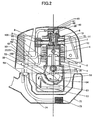
- FIG. 1 and Fig.2 respectively illustrate a cross-sectional side elevation view of a four-cycle engine.
- the four-cycle engine is made up of a lightweight aluminum housing including a cylinder block 1 having a cylindrical bore 2 formed therein.
- a crankshaft 3 is pivotably mounted within the engine block 1 in a conventional manner.
- a piston 4 slides within the cylindrical bore 2 and is connected to the crankshaft by a connecting rod 5.
- a cylinder head 6 is affixed to the engine block 1 to define an enclosed combustion chamber 7.
- the cylinder head 6 is provided with an intake port 8 coupled to an insulator 9 and carburetor 100 and selectively connected to the combustion chamber 7 by an intake valve 10.
- 101 is a filter element of air cleaner, which eliminates dust from the intake air into the engine.
- the cylinder head 6 is also provided with an exhaust port 11 connected to a muffler 12 and selectively connected to the combustion chamber 7 by an exhaust valve 13.
- the cylinder axis 14 of four-cycle engine is generally upright when in normal use.
- the cylinder block 1 is connected to a crankcase-A 15 and crankcase-B 16 that provide an enclosed oil reservoir 17.
- the crankcase-A 15 and crankcase-B 16 mate with each other at the interface including cylinder axis 14.
- the oil reservoir 17 is relatively deep so that there is ample clearance between the crankshaft 3 and the level of the oil within the oil reservoir during normal use.
- the crankshaft 3 is provided with an axial shaft member 18 having an output end 19 adapted to be coupled to a flywheel 20 which has an implement input member 21.
- An input end 22 of axial shaft member 18 is coupled to a counterweight web 23.
- a crankpin 24 is affixed to counterweight webs 23, 25 and is parallel to and radially offset from the axial shaft 18.
- the crankpin 24 pivotally cooperates with a roller bearing 26 mounted in connecting rod 5.
- the axial shaft 18 and 27 of crankshaft 3 are pivotably attached to a set of crankcase-A 15 and crankcase-B 16 by a pair of bearings 28 and 29. At the side of bearing 29 is a crank gear 30.
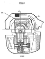
- the camshaft drive and valve lifter mechanism is best illustrated in FIGS. 1 and 3 .
- the crank gear 30 is mounted on the crankshaft, which in turn drives a cam gear 31 with twice the number of teeth as the crank gear 30 resulting in the camshaft 32 rotating in one-half engine speed.
- the cam gear 31 is affixed to a camshaft 32 which is journaled to the cylinder block 1 and includes a rotary cam lobe 33. In the embodiment illustrated, a single cam lobe is utilized for driving both the intake and exhaust valve.
- followers 34 and 35 are pivotably connected to the cylinder block 1 by a pivot pin 36.
- Push rods 37 and 38 extend between camshaft followers 34 and 35 and rocker arms 39 and 40 located within the cylinder head 6.
- the cam, push rods 37, 38 and rocker arms 39, 40 are part of a valve train assembly.
- Affixed to the cylinder head 6 is a valve cover 41 which defines therebetween an enclosed valve chamber 42.
- a wall 43 surrounds the intake and exhaust push rods 37 and 38 in a conventional manner in order to prevent the entry of dirt into the engine.
- a pump 44 such as a trochoid pump is placed at the side of cam gear 31.
- 45 is the inner rotor and 46 is the outer rotor of the pump 44.
- a gear pump or plunger pump may be used.
- the inner rotor 45 is driven by the cam gear 31 and the outer rotor 46 is rotated following the rotation of the inner rotor 45.
- Lubrication oil is inhaled from the passage 47.
- An end of the passage 47 leads to the oil entrance of the pump.
- the other end of passage 47 is connected to a flexible tube 48.
- the other end of flexible tube is connected to a filter with weight 49. By the weight 49, the entrance of the flexible tube is dipped in the oil in the oil reservoir 17 at any orientation of the engine.
- the oil pushed out by the pump is lead to the cylinder bore through an inner hole 50 of the cam shaft 32 and a hole 51 at the cylinder wall as illustrated in Fig. 1 .
- the other hole 52 at the wall of the cam shaft 32 leads oil to the valve actuating train through a passage 53 on the cam gear 31. Accordingly, the engine parts inside the cylinder and the valve train room are then mist lubricated by the oil splashed by means of the rotation of and/or the centrifugal force generated by the rotating parts such as web 23, 25 and the cam gear 31.
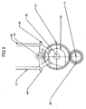
- a first wall or a circular arc wall 54 surrounding the counterweight web 23,25 of the crank shaft 3 is extended from the wall of crankcase-A 15 and crankcase-B 16.
- the arc wall 54 is co-axial with the axis of the counterweight web 23 or 25. The distance between the web 23 or 25 and the inner face of the arc wall is made narrow for the reason as set forth below.
- the end 55 of arc wall 54, which is down stream of the rotation of web 23 or 25, is connected to the inner wall of crankcase-A 15 or crankcase-B 16, while an oil entrance 56 is provided between arc wall 54 and the wall of crankcase-A and crankcase B as illustrated in Figure 2 .
- scrolled wall 57 Around the entrance 56, a second wall or a scrolled wall 57 is provided. As illustrated in Fig. 2 , scrolled wall 57 has a distance from the arc wall 54. The distance increases as the rotation of crank web. The end of wall 57 located at the upper stream of rotation of counterweight web 23 or 25 is connected to the inner wall of crankcase-A 15 or crankcase-B 16. The other side of the space between the wall 54 and the wall 57 has an outlet 58, which is located at the top of the oil reservoir 17.
- the arc wall 54 and the scrolled wall 57 are overlapped as illustrated in Fig. 2 .
- an extended wall 59 is provided to the oil reservoir 17.
- a breather pipe 61 is opened through the valve cover 41 and is connected to an air cleaner case 62 through a breather pipe 63.
- oil separating deflector 102 is provided in the air cleaner case 62. The breathing oil mist through a tube is separated into oil lean gas and oil rich gas by the deflector 102.
- a return tube 64 interconnects the air cleaner case 62 and the cylinder wall in which a return hole 65 is provided so as to open and close with reciprocating motion of piston 4 and the oil rich mist returns into the crankcase only when the pressure in the crankcase is negative.
- the oil lean mist is inhaled to the carburetor through filter element 101.
- a spark plug 66 is installed in a spark plug hole formed in the cylinder head.
- 67 is an ignition coil.
- a re-coil starter 68 having a re-winding rope 69 is provided at a side of crank shaft 3.
- cooling air entrance 70 is provided which inhales cooling air of engine generated by rotation of blade 71 on the flywheel 20.
- a fuel tank 72 is provided below the oil reservoir 17, adequately spaced apart therefrom.
- a fuel filter 73 and a fuel pipe 74 are provided through which fuel is inhaled into the carburetor 100.
- the four-cycle engine is provided with a very compact combustion chamber 7.
- lubricating oil is immediately inhaled to oil pump 44 by rotation of rotors 45, 46 through flexible tube 48.
- Lubricating oil is splashed into the cylinder bore through the holes 50 and 51 and into the valve mechanism room through the hole 52 and the passage 53.
- the weight supported by and connected to the flexible tube 48 oil is inhaled at any posture of the engine.
- the oil mist in the room in which the valve actuating parts are installed lubricates the valve train and then flows into the air cleaner box through the passages 61 and 63.
- the circular arc wall 54 surrounds around the counterweight webs 23, 25 with a slight distance from the web.
- the scroll shaped wall 57 has gradually increased distance from said wall to the direction of the web and has partial overlap with the circular arc wall 54.
- the crankshaft webs 23 and 25 splash the oil to mist lubricate the internal engine parts.
- the oil is forced to return into the oil reservoir 17 guided by the scroll shaped wall 57 at any posture of engine due to the viscosity of the oil situated between the webs (23, 25) and the circular arc wall (54) as well as the centrifugal force generated by the webs (23, 25).
- lubrication oil is kept in oil reservoir 17 helped by the extended wall 59 and oil is prevented from flowing into the cylinder head part.
- small light weight four cycle engines made in accordance with the present invention will be particularly suitable for the use with hand-held or transportable power tool having low emissions and is sufficiently light to be carried and/or transported by an operator.
- various kinds of lubricating method for hand-held or transportable power tool have been presented. However, most of them require complicated check valve systems to control flow of lubricating oil in the engines and to prevent oil from flowing into cylinder head part when engine is inclined to be upside down. In the present invention, however, no additional parts are required to form the check valve mechanism, thereby making the engine structure simpler and decreases weight and cost.
- the pump in the present invention is very low cost because it can be made easily by machining and/or injection mold process, powder compaction molding.
- Another advantage of this invention is better cooling performance.
- some engines using, so to speak, dry sump lubrication In dry sump lubrication, over heating of oil might ruin lubrication performance.
- the present invention looks like dry sump but differs in the following points. First, a lot of lubrication oil is sent by oil pump. Second, there is a space between arc and scrolled walls. This space allows to prevent heat flow between crankcase and oil reservoir and consequently oil temperature of oil in reservoir is lower than the current dry sump engines. Further, as illustrated in Fug.
- cooling air is inhaled around the fuel tank, wherein, since temperature of oil reservoir is lower, the cooling air is not heated so much as the current dry sump engines and, as the results, engine can be cooled effectively.
- the improved cooling may improve emission by reducing energy to cool engine.
Landscapes
- Engineering & Computer Science (AREA)
- Mechanical Engineering (AREA)
- General Engineering & Computer Science (AREA)
- Chemical & Material Sciences (AREA)
- Combustion & Propulsion (AREA)
- Lubrication Of Internal Combustion Engines (AREA)
- Lubrication Details And Ventilation Of Internal Combustion Engines (AREA)
Claims (9)
- Einzylinder-Viertalct-Ottomotor zum Montieren auf einem angetriebenen Werkzeug, umfassend:einen Zylinderblock (1), welcher einen Zylinder, einen Zylinderkopf (6), einen Kolben aufweist, welcher zum Hin- und Herbewegen in dem Zylinder montiert ist, wobei der Zylinderkopf eine Luft-Kraftstoff-Verbrennungskammer (7) definiert;eine Luft-Kraftstoff-Mischung-Einlassöffnung (8) und eine Abgasöffnung (11) in dem Zylinderkopf;einen Ventildeckel (41) auf dem Zylinderkopf, welcher eine Ventilkammer (42) definiert;ein Einlassventil (10) und ein Auslassventil (13), welche in der Einlassöffnung bzw. der Auslassöffnung zum Hin- und Herbewegen zwischen Öffnung-offen- und Öffnung-geschlossen-Positionen montiert sind;ein Ventilbetätigungs-Ventilzug, wobei der Ventilzug zumindest einen Kipphebel (39, 40) und zumindest eine Ventilzug-Stößelstangen-(37, 38)-Anordnung umfasst, welche sich an einem Ende davon innerhalb der Ventilkammer erstreckt und den Kipphebel in Eingriff nimmt;eine Kurbelwelle (3), welche drehbar in einem Kurbelgehäuse (15, 16) montiert ist, wobei die Kurbelwelle einen Kurbelabschnitt und zumindest eine Gegengewichtfläche (23, 25) umfasst;eine Verbindungsstange (6), welche gelenkige Verbindungen an einem Ende davon zu dem Kolben und an dem gegenüberliegenden Ende davon zu dem Kurbelabschnitt aufweist, wodurch eine Kolbenverbindende Stangen-Kurbelwellen-Anordnung gebildet wird;einen Nocken (33), welcher drehbar in einem Nockengehäuse montiert ist, wobei der Nocken antreibbar mit der Kurbelwelle verbunden ist, welche ein Kurvengetriebe (31) aufweist, wobei der Nocken mit der halben Kurbelwellengeschwindigkeit angetrieben wird, wobei das gegenüberliegende Ende der Stößelstangen-Anordnung antreibbar mit dem Nocken verbunden ist, wobei die Stößelstangen-Anordnung mit einer hin- und herbewegenden Bewegung auf eine Drehung des Nockens hin betätigt wird;ein Schmierölreservoir (17), welches unterhalb des Kurbelgehäuses gebildet ist; undeine Ölpumpe (44), welche antreibbar mit der Kurvengetriebe-Nocken-Anordnung verbunden ist, wobei die Pumpe Schmieröl von dem Ölreservoir aufnimmt und das Öl in den Zylinder und die Ventilkammer spritzt, um die Motorteile im Inneren des Zylinders und der Ventilkammer zu schmieren;dadurch gekennzeichnet, dass der Motor weiterhin umfasst:eine erste Wand (54), welche zumindest teilweise die Fläche in einem geringen Abstand davon umgibt; undeine zweite Wand (57), welche zumindest teilweise die erste Wand (54) in einem Abstand umgibt, welcher graduell in stromabwätiger Drehrichtung der Fläche zunimmt;wobei die Fläche das Öl spritzt, um die inneren Motorteile zu schmieren, und wobei nach dem Schmieren der inneren Motorteile das Öl dazu gezwungen wird, in das Ölreservoir geleitet durch die zweite Wand zurückzukehren, während sich die Fläche aufgrund der Viskosität des Öls zwischen der Fläche und der ersten Wand dreht.
- Motor gemäß Anspruch 1, welcher weiterhin ein Luftreinigungsgehäuse (62) umfasst, welches mit der Ventilkammer (42) über einen ersten Durchgang (63), durch welchen Atmungsölnebelgas fließt, einen zweiten Durchgang (64), welcher das Luftreinigungsgehäuse (62) mit dem Kurbelgehäuse oder Zylinderblock verbindet, und ein Ventil (4, 65) verbunden ist, welches an dem Eingang des Durchgangs in das Kurbelgehäuse vorgesehen ist, wobei das Öffnen des Ventils durch eine Hin- und Herbewegung des Kolbens gesteuert wird, und wobei das Ventil öffnet, wenn Druck in dem Kurbelgehäuse negativ ist, und schließt, wenn der Druck in dem Kurbelgehäuse positiv ist, wodurch die Ölnebelfluß-Steuerventil-Struktur einen Schmierölnebelfluss-Kreislauf von der Ventilkammer zu dem Kurbelgehäuse oder Zylinderblock durch das Luftreinigungsgehäuse aufbaut.
- Motor gemäß Anspruch 1, wobei die Ölpumpe (44) integral an einem Nocken oder Kurvengetriebe (31) angebracht ist.
- Motor gemäß Anspruch 1, wobei die Ölpumpe (44) eine Trochoidenpumpe ist.
- Motor gemäß Anspruch 1, wobei die Ölpumpe (44) eine Zahnradpumpe ist.
- Motor gemäß Anspruch 1, wobei die Ölpumpe (44) eine Plungerpumpe ist.
- Handgehaltenes transportables oder stationäres angetriebenes Werkzeug, welches durch den Motor gemäß Anspruch 1 angetrieben wird, wobei das angetriebene Werkzeug durch eine horizontale oder vertikale oder schräge Triebachse angetrieben wird.
- Motor gemäß Anspruch 1, wobei die zweite Wand (57) eine erweiterte Wand (59) aufweist, welche verhindert, dass das Öl in dem Ölreservoir heraus fließt, wenn der Motor in irgendeiner Position geneigt ist.
- Motor gemäß den Ansprüchen 1 bis 8, wobei die ersten und zweiten Wände (54, 57) durch Verbinden eines Satzes des Kurbelgehäuses gebildet werden.
Applications Claiming Priority (1)
| Application Number | Priority Date | Filing Date | Title |
|---|---|---|---|
| US70570805P | 2005-08-03 | 2005-08-03 |
Publications (2)
| Publication Number | Publication Date |
|---|---|
| EP1749984A1 EP1749984A1 (de) | 2007-02-07 |
| EP1749984B1 true EP1749984B1 (de) | 2008-08-27 |
Family
ID=37102102
Family Applications (1)
| Application Number | Title | Priority Date | Filing Date |
|---|---|---|---|
| EP06253926A Not-in-force EP1749984B1 (de) | 2005-08-03 | 2006-07-27 | Schmiervorrichtung für eine Viertaktbrennkraftmaschine eines Kraftwerkzeugs |
Country Status (4)
| Country | Link |
|---|---|
| US (1) | US7287508B2 (de) |
| EP (1) | EP1749984B1 (de) |
| CN (1) | CN1908389B (de) |
| DE (1) | DE602006002450D1 (de) |
Families Citing this family (34)
| Publication number | Priority date | Publication date | Assignee | Title |
|---|---|---|---|---|
| US7624714B2 (en) * | 2005-08-03 | 2009-12-01 | Etg Limited | Engine lubrication method |
| JP2007309234A (ja) * | 2006-05-19 | 2007-11-29 | Honda Motor Co Ltd | 内燃機関の潤滑装置 |
| TW200905065A (en) * | 2007-07-17 | 2009-02-01 | Si-Liang Lin | Engine lubrication loop device |
| US9187083B2 (en) | 2009-09-16 | 2015-11-17 | Polaris Industries Inc. | System and method for charging an on-board battery of an electric vehicle |
| EP2308708B1 (de) * | 2009-09-16 | 2016-08-17 | swissauto powersport llc | Elektrofahrzeug mit Reichweitenverlängerung |
| JP5463111B2 (ja) * | 2009-09-24 | 2014-04-09 | 株式会社マキタ | 携帯型4サイクルエンジンの潤滑装置 |
| US8695563B2 (en) * | 2009-09-24 | 2014-04-15 | Makita Corporation | Lubrication system for four-stroke engine |
| JP5413107B2 (ja) * | 2009-09-30 | 2014-02-12 | 日立工機株式会社 | 4サイクルエンジンおよびそれを備える刈払機ならびにエンジン工具 |
| EP2483532B1 (de) | 2009-09-30 | 2016-11-09 | Hitachi Koki Co., Ltd. | Viertaktmotor, heckenschere und motorengetriebenes werkzeug damit |
| JP5413108B2 (ja) * | 2009-09-30 | 2014-02-12 | 日立工機株式会社 | 4サイクルエンジンおよびそれを備えた刈払機ならびにエンジン工具 |
| JP5608452B2 (ja) * | 2010-07-14 | 2014-10-15 | 株式会社マキタ | 作業機用エンジン及びこれを用いた作業機 |
| US8490597B2 (en) | 2010-11-29 | 2013-07-23 | Etg Limited | Vertical and horizontal engine |
| US8490596B2 (en) | 2010-11-29 | 2013-07-23 | Etg Limited | Vertical and horizontal engine |
| JP5873636B2 (ja) * | 2011-02-14 | 2016-03-01 | 株式会社マキタ | エンジン |
| US8627809B2 (en) | 2011-09-22 | 2014-01-14 | Etg Limited | Engine lubrication method |
| US20150020760A1 (en) * | 2011-09-22 | 2015-01-22 | Etg Limited | Four-cycle Internal Combustion Engine |
| JP5803578B2 (ja) * | 2011-10-31 | 2015-11-04 | スズキ株式会社 | 単気筒エンジンの潤滑構造 |
| CN103511115B (zh) * | 2012-06-15 | 2017-12-29 | 苏州科瓴精密机械科技有限公司 | 发动机喷油系统 |
| CN103206283B (zh) * | 2013-01-30 | 2015-11-25 | 祥天控股(集团)有限公司 | 微型空气动力发动机的柱塞式喷油泵 |
| WO2015182510A1 (ja) * | 2014-05-30 | 2015-12-03 | 日立工機株式会社 | エンジン及びエンジン作業機 |
| US10300786B2 (en) | 2014-12-19 | 2019-05-28 | Polaris Industries Inc. | Utility vehicle |
| JP6357119B2 (ja) * | 2015-02-05 | 2018-07-11 | 株式会社マキタ | エンジンの潤滑装置 |
| EP3468823B1 (de) | 2016-06-14 | 2024-09-04 | Polaris Industries Inc. | Hybridnutzfahrzeug |
| CN106855091A (zh) * | 2017-03-15 | 2017-06-16 | 乐山职业技术学院 | 一种座椅及车辆 |
| CN106931062A (zh) * | 2017-03-15 | 2017-07-07 | 乐山职业技术学院 | 减震装置及车辆 |
| US10780770B2 (en) | 2018-10-05 | 2020-09-22 | Polaris Industries Inc. | Hybrid utility vehicle |
| FR3090518B1 (fr) | 2018-12-19 | 2022-02-25 | Martur France Automotive Seating And Interiors Sarl | Elément de siège de véhicule pourvu d'une coiffe et procédé de fabrication de cet élément de siège de véhicule |
| CN113767023B (zh) | 2019-04-30 | 2024-09-24 | 北极星工业有限公司 | 车辆 |
| US11370266B2 (en) | 2019-05-16 | 2022-06-28 | Polaris Industries Inc. | Hybrid utility vehicle |
| US12187127B2 (en) | 2020-05-15 | 2025-01-07 | Polaris Industries Inc. | Off-road vehicle |
| US11691674B2 (en) | 2020-05-15 | 2023-07-04 | Polaris Industries Inc. | Off-road vehicle |
| US12485981B2 (en) | 2021-03-24 | 2025-12-02 | Polaris Industries Inc. | Electric recreational vehicle |
| CA3156559A1 (en) | 2021-05-05 | 2022-11-05 | Polaris Industries Inc. | Exhaust assembly for a utility vehicle |
| MX2023006716A (es) | 2022-06-13 | 2023-12-14 | Polaris Inc | Tren de potencia para vehiculo utilitario. |
Family Cites Families (8)
| Publication number | Priority date | Publication date | Assignee | Title |
|---|---|---|---|---|
| FR618367A (fr) * | 1926-06-23 | 1927-03-08 | Dispositif de graissage pour moteurs | |
| US2111242A (en) * | 1936-05-16 | 1938-03-15 | Harley Davidson Motor Co Inc | Lubricating system for internal combustion engines |
| DE1948186A1 (de) * | 1969-09-24 | 1971-04-01 | Daimler Benz Ag | Kolbenbrennkraftmaschine |
| US5241932A (en) | 1991-12-02 | 1993-09-07 | Ryobi Outdoor Products | Operator carried power tool having a four-cycle engine |
| TW487770B (en) * | 1995-12-15 | 2002-05-21 | Honda Motor Co Ltd | Lubricating system in a 4-stroke engine |
| DE69807294T2 (de) * | 1997-06-26 | 2003-04-17 | Ishikawajima-Shibaura Machinery Co., Ltd. | Schmierölversorgungsanlage für Viertaktbrennkraftmaschine |
| US6213079B1 (en) * | 1998-06-03 | 2001-04-10 | Fuji Robin Kabushiki Kaisha | Lubricating apparatus for four-cycle engines |
| JP3244477B2 (ja) * | 1998-12-28 | 2002-01-07 | 富士ロビン株式会社 | 4サイクルエンジンの潤滑構造 |
-
2006
- 2006-07-27 EP EP06253926A patent/EP1749984B1/de not_active Not-in-force
- 2006-07-27 DE DE602006002450T patent/DE602006002450D1/de active Active
- 2006-08-02 US US11/498,608 patent/US7287508B2/en not_active Expired - Fee Related
- 2006-08-03 CN CN2006101092542A patent/CN1908389B/zh not_active Expired - Fee Related
Also Published As
| Publication number | Publication date |
|---|---|
| CN1908389A (zh) | 2007-02-07 |
| US20070028887A1 (en) | 2007-02-08 |
| US7287508B2 (en) | 2007-10-30 |
| DE602006002450D1 (de) | 2008-10-09 |
| CN1908389B (zh) | 2010-04-07 |
| EP1749984A1 (de) | 2007-02-07 |
Similar Documents
| Publication | Publication Date | Title |
|---|---|---|
| EP1749984B1 (de) | Schmiervorrichtung für eine Viertaktbrennkraftmaschine eines Kraftwerkzeugs | |
| US7624714B2 (en) | Engine lubrication method | |
| US8281758B2 (en) | Engine lubrication method | |
| EP0884455B1 (de) | Brennkraftmaschine | |
| US6363904B1 (en) | Multi-position, operator-carried, four-cycle engine | |
| US8490597B2 (en) | Vertical and horizontal engine | |
| JP2000192849A (ja) | 4サイクルエンジンの可搬式作業機器 | |
| US8627809B2 (en) | Engine lubrication method | |
| US8490596B2 (en) | Vertical and horizontal engine | |
| US20150000633A1 (en) | Vertical and Horizontal Engine | |
| US20150020760A1 (en) | Four-cycle Internal Combustion Engine | |
| US20130074792A1 (en) | Engine Lubrication Method | |
| US20130154273A1 (en) | Engine Generator | |
| HK1006635B (en) | Operator carried power tool having a four-cycle engine | |
| JPH0653730U (ja) | 縦軸オ−バ−ヘッドバルブエンジンで駆動される地表移動作業機械 |
Legal Events
| Date | Code | Title | Description |
|---|---|---|---|
| PUAI | Public reference made under article 153(3) epc to a published international application that has entered the european phase |
Free format text: ORIGINAL CODE: 0009012 |
|
| 17P | Request for examination filed |
Effective date: 20060807 |
|
| AK | Designated contracting states |
Kind code of ref document: A1 Designated state(s): AT BE BG CH CY CZ DE DK EE ES FI FR GB GR HU IE IS IT LI LT LU LV MC NL PL PT RO SE SI SK TR |
|
| AX | Request for extension of the european patent |
Extension state: AL BA HR MK YU |
|
| AKX | Designation fees paid |
Designated state(s): DE FR IT |
|
| GRAP | Despatch of communication of intention to grant a patent |
Free format text: ORIGINAL CODE: EPIDOSNIGR1 |
|
| GRAS | Grant fee paid |
Free format text: ORIGINAL CODE: EPIDOSNIGR3 |
|
| GRAA | (expected) grant |
Free format text: ORIGINAL CODE: 0009210 |
|
| AK | Designated contracting states |
Kind code of ref document: B1 Designated state(s): DE FR IT |
|
| REF | Corresponds to: |
Ref document number: 602006002450 Country of ref document: DE Date of ref document: 20081009 Kind code of ref document: P |
|
| PLBE | No opposition filed within time limit |
Free format text: ORIGINAL CODE: 0009261 |
|
| STAA | Information on the status of an ep patent application or granted ep patent |
Free format text: STATUS: NO OPPOSITION FILED WITHIN TIME LIMIT |
|
| 26N | No opposition filed |
Effective date: 20090528 |
|
| PGFP | Annual fee paid to national office [announced via postgrant information from national office to epo] |
Ref country code: FR Payment date: 20110729 Year of fee payment: 6 |
|
| PGFP | Annual fee paid to national office [announced via postgrant information from national office to epo] |
Ref country code: DE Payment date: 20110722 Year of fee payment: 6 |
|
| PGFP | Annual fee paid to national office [announced via postgrant information from national office to epo] |
Ref country code: IT Payment date: 20110728 Year of fee payment: 6 |
|
| REG | Reference to a national code |
Ref country code: FR Ref legal event code: ST Effective date: 20130329 |
|
| PG25 | Lapsed in a contracting state [announced via postgrant information from national office to epo] |
Ref country code: FR Free format text: LAPSE BECAUSE OF NON-PAYMENT OF DUE FEES Effective date: 20120731 Ref country code: DE Free format text: LAPSE BECAUSE OF NON-PAYMENT OF DUE FEES Effective date: 20130201 |
|
| REG | Reference to a national code |
Ref country code: DE Ref legal event code: R119 Ref document number: 602006002450 Country of ref document: DE Effective date: 20130201 |
|
| PG25 | Lapsed in a contracting state [announced via postgrant information from national office to epo] |
Ref country code: IT Free format text: LAPSE BECAUSE OF NON-PAYMENT OF DUE FEES Effective date: 20120727 |