EP1749598B1 - Casting mold forming apparatus and metal mold unit for use therein - Google Patents
Casting mold forming apparatus and metal mold unit for use therein Download PDFInfo
- Publication number
- EP1749598B1 EP1749598B1 EP05727070A EP05727070A EP1749598B1 EP 1749598 B1 EP1749598 B1 EP 1749598B1 EP 05727070 A EP05727070 A EP 05727070A EP 05727070 A EP05727070 A EP 05727070A EP 1749598 B1 EP1749598 B1 EP 1749598B1
- Authority
- EP
- European Patent Office
- Prior art keywords
- foam mixture
- metal mold
- mold
- measuring
- mixture
- Prior art date
- Legal status (The legal status is an assumption and is not a legal conclusion. Google has not performed a legal analysis and makes no representation as to the accuracy of the status listed.)
- Active
Links
- 239000002184 metal Substances 0.000 title claims abstract description 74
- 238000005266 casting Methods 0.000 title description 2
- 239000000203 mixture Substances 0.000 claims abstract description 173
- 239000006260 foam Substances 0.000 claims abstract description 165
- 239000002245 particle Substances 0.000 claims abstract description 26
- 238000000465 moulding Methods 0.000 claims abstract description 19
- 239000007789 gas Substances 0.000 claims abstract description 6
- 230000007246 mechanism Effects 0.000 claims description 28
- 239000000523 sample Substances 0.000 claims description 16
- 238000010438 heat treatment Methods 0.000 claims description 4
- 230000004580 weight loss Effects 0.000 claims description 2
- XLYOFNOQVPJJNP-UHFFFAOYSA-N water Substances O XLYOFNOQVPJJNP-UHFFFAOYSA-N 0.000 abstract description 27
- 239000003232 water-soluble binding agent Substances 0.000 abstract description 16
- 238000002347 injection Methods 0.000 abstract description 11
- 239000007924 injection Substances 0.000 abstract description 11
- 239000012615 aggregate Substances 0.000 abstract description 6
- 230000000694 effects Effects 0.000 abstract description 3
- 238000000034 method Methods 0.000 description 20
- VYPSYNLAJGMNEJ-UHFFFAOYSA-N Silicium dioxide Chemical compound O=[Si]=O VYPSYNLAJGMNEJ-UHFFFAOYSA-N 0.000 description 17
- 239000004576 sand Substances 0.000 description 11
- 239000012530 fluid Substances 0.000 description 8
- 238000003908 quality control method Methods 0.000 description 8
- 239000004372 Polyvinyl alcohol Substances 0.000 description 3
- 229920002451 polyvinyl alcohol Polymers 0.000 description 3
- 239000000377 silicon dioxide Substances 0.000 description 3
- 239000011230 binding agent Substances 0.000 description 2
- 230000000149 penetrating effect Effects 0.000 description 2
- 230000005540 biological transmission Effects 0.000 description 1
- 238000001816 cooling Methods 0.000 description 1
- 238000001704 evaporation Methods 0.000 description 1
- 239000012212 insulator Substances 0.000 description 1
- 239000000463 material Substances 0.000 description 1
- 238000005259 measurement Methods 0.000 description 1
- 238000005070 sampling Methods 0.000 description 1
Images


Classifications
-
- B—PERFORMING OPERATIONS; TRANSPORTING
- B22—CASTING; POWDER METALLURGY
- B22C—FOUNDRY MOULDING
- B22C19/00—Components or accessories for moulding machines
- B22C19/04—Controlling devices specially designed for moulding machines
-
- B—PERFORMING OPERATIONS; TRANSPORTING
- B22—CASTING; POWDER METALLURGY
- B22C—FOUNDRY MOULDING
- B22C15/00—Moulding machines characterised by the compacting mechanism; Accessories therefor
- B22C15/02—Compacting by pressing devices only
- B22C15/08—Compacting by pressing devices only involving pneumatic or hydraulic mechanisms
-
- B—PERFORMING OPERATIONS; TRANSPORTING
- B22—CASTING; POWDER METALLURGY
- B22C—FOUNDRY MOULDING
- B22C15/00—Moulding machines characterised by the compacting mechanism; Accessories therefor
- B22C15/23—Compacting by gas pressure or vacuum
-
- B—PERFORMING OPERATIONS; TRANSPORTING
- B22—CASTING; POWDER METALLURGY
- B22C—FOUNDRY MOULDING
- B22C15/00—Moulding machines characterised by the compacting mechanism; Accessories therefor
- B22C15/23—Compacting by gas pressure or vacuum
- B22C15/24—Compacting by gas pressure or vacuum involving blowing devices in which the mould material is supplied in the form of loose particles
- B22C15/245—Blowing tubes
-
- B—PERFORMING OPERATIONS; TRANSPORTING
- B22—CASTING; POWDER METALLURGY
- B22C—FOUNDRY MOULDING
- B22C5/00—Machines or devices specially designed for dressing or handling the mould material so far as specially adapted for that purpose
- B22C5/12—Machines or devices specially designed for dressing or handling the mould material so far as specially adapted for that purpose for filling flasks
Landscapes
- Engineering & Computer Science (AREA)
- Mechanical Engineering (AREA)
- Casting Or Compression Moulding Of Plastics Or The Like (AREA)
- Molds, Cores, And Manufacturing Methods Thereof (AREA)
- Mold Materials And Core Materials (AREA)
- Moulds For Moulding Plastics Or The Like (AREA)
- Casting Devices For Molds (AREA)
- Blow-Moulding Or Thermoforming Of Plastics Or The Like (AREA)
Abstract
Description
- This invention relates to an apparatus for molding a mold by pressurizing a foam mixture composed of particles of aggregate, water-soluble binders, and water, and injecting it into a cavity of a heated metal mold. This invention also relates to a metal mold used in the apparatus.
- Recently, a method for molding a mold in which water soluble binders are used as a binder for particles of aggregate and are hardened by heating them and evaporating their water is frequently used because of a good frangible property of the mold after casting.
- There is an apparatus for molding such a mold, comprising: a cylinder extending upward and downward, a plunger disposed in the cylinder and sliding upward and downward in the cylinder, and a gate for opening and closing the opening disposed at the bottom of the cylinder, wherein these elements constitute a means for injecting fluid foundry sand into a metal mold. The apparatus can move upward and downward. The apparatus is also connected to a mixer to prepare the fluid foundry sand at the opening disposed at the center of the cylinder.
- In this conventional apparatus, an additional gate is disposed at the center of the cylinder, the positions of the gate disposed at the bottom and the center of the cylinder are changed, and the position of the plunger is changed to control the quantity of the fluid foundry sand to be injected into the metal mold. (See patent document 1.)
- In this conventional apparatus, however, it is difficult to control the quantity of the fluid foundry sand to be injected into the metal mold in order to have it correspond to the cavity of the metal mold. Further, since more fluid foundry sand than can be filled within the cavity of the mold should be loaded in the cylinder, some of the fluid foundry sand remains in the cylinder after it is injected into the cavity of the mold. Since this remainder of the fluid foundry sand is left, it is waisted.
- Further, it sometimes occurs that there is not enough fluid foundry sand in the cylinder to fill the cavity of the metal mold.
- Further, since the foam mixture, which is the material for making a mold, contains the water-soluble binders as the binder for the particles of aggregate and contains a large quantity of water, it takes a long time for the foam mixture to be hardened in the metal mold.
- Patent document 1: Japanese Patent Laid-open
Publication No.S55-54241 - Patent document 2: Japanese Patent Laid-open
Publication No.H11-129054 - The purpose of this invention is to solve the above problems of the conventional apparatus. The invention is defined in the claims.
- Further, to solve the problems mentioned above, which occur in the process for molding a mold by using the foam mixture made by mixing the particles of aggregate, more than one kind of water-soluble binders, and water, and a metal mold for molding a mold by being filled with the foam mixture, is provided with a means for communicating gases from the cavity of the metal mold to the outside of the mold so that the particles of aggregate cannot pass through it.
- By using this apparatus for molding a mold, the mold is made based on the following steps:
- a closing step to close the injection hole by the means for closing and opening the injection hole,
- a mixing step to mix a predetermined quantity of the particles of aggregate, the water-soluble binders, and the water contained in the means for containing the foam mixture, wherein the predetermined quantity is more than the quantity that can be held within the cavity of the metal mold,
- a connecting step to connect the means for containing the foam mixture to the heated metal mold after mixing, and
- an infecting step to inject the foam mixture into the cavity of the metal mold by pressurizing the mixture.
- Then, the particles of aggregate, the water-soluble binders, and the water are poured in the means for containing the foam mixture and are mixed for the next process for molding a mold.
- As mentioned above, since the apparatus is at least provided with any means or any combination of means for measuring the temperature of the particles of aggregate or the foam mixture, or the viscosity of the foam mixture, or the moisture of the foam mixture, when the temperature of the particles of aggregate or the foam mixture is too high, it is possible to control the temperature of a heater. Further, when the viscosity of the foam mixture is too low, water can be added to it from a means for providing water, and then the foam mixture is further mixed, and when the moisture of the foam mixture is too low, water can also be added to the foam mixture from the means for providing the water, and the foam mixture is further mixed. Thus, the cavity of the metal mold can be filled with a foam mixture having proper properties.
- By using the metal mold mentioned above, the steam generated from the foam mixture when the metal mold is heated can be released by passing it through the means for communicating gases from the cavity of the metal mold to the outside of the mold.
- As explained above, the apparatus according to the present invention has the following constitution:
- an apparatus for molding a mold by pressurizing a foam mixture composed of particles of aggregate, water-soluble binders, and water, and injecting it into a cavity of a heated metal mold, the apparatus comprising:
- a hollow rectangular-parallelepiped body having a bottom plate, the bottom plate having an injection hole to inject the foam mixture,
- a means for containing the foam mixture having functions as a mixing bath to mix particles of aggregate, water-soluble binders, and water, and as a pressurized vessel to inject the foam mixture into a metal mold, and
- a means for closing and opening the injecting hole.
- Since the mold may be made by using this apparatus based on the following steps:
- an adding step to add the particles of aggregate, the water-soluble binders, and the water to the means for containing the foam mixture, after filling the cavity of the metal mold with the foam mixture contained in the means for containing the foam mixture, and then
- a mixing step to mix the particles of aggregate, the water-soluble binders, and the water to cause them to foam,
- the foam mixture which remains in the means for containing it after injecting the mixture into the cavity of the metal mold can be used effectively at the next steps for making a mold.
- Thus, while in the conventional apparatus the remaining foam mixture in the means for containing the foam mixture is not recovered, the apparatus according to this invention has an excellent effect because the remainder can be used effectively.
- Further, since the apparatus is provided with any means or any combination of means for measuring the temperature of the particles of aggregate or the foam mixture, the viscosity of the foam mixture, or the moisture of the foam mixture, when the temperature of the particles of aggregate or the foam mixture is too high, it is possible to control the temperature of a heater, and when the viscosity of the foam mixture is too low, water can be added to the foam mixture from a means for providing water, and then the foam mixture is further mixed, and when the moisture of the foam mixture is too low, water can also be added to the foam mixture, and then the foam mixture is further mixed. Thus, the cavity of the metal mold can be filled with a foam mixture having proper properties.
- Further, in the apparatus for molding a mold by using the foam mixture made by mixing the particles of aggregate, more than one kind of the water-soluble binders, and water, and using the metal mold, since the metal mold for molding a mold by filling it with the foam mixture is provided with the means for communicating gases from the cavity of the metal mold to the outside of the mold so that the particles of aggregate cannot pass through it, the steam generated from the foam mixture can be released by passing it through the means for communicating gases. Thus, the metal mold according to this invention has an excellent effect because the period for hardening the foam mixture can be significantly reduced.
-
-
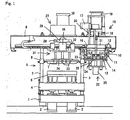
Fig. 1 shows an elevation view and a partial section view of an apparatus for molding a mold of a preferred embodiment of the invention. -
Fig. 2 shows a drawing to explain the operations of the apparatus for molding a mold, indicating the state wherein the mixture in the means for containing the foam mixture is injected into the horizontally separated metal mold. -
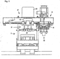
Fig. 3 shows an elevation view and a partial section view of an apparatus for molding a mold of an embodiment of the invention. -
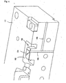
Fig. 4 shows a view of a portion of the lower part of the metal mold. -
Fig. 5 shows a perspective view of the metal mold of an embodiment of the invention. -
Fig. 6 shows an enlarged and detailed view of the part "A" ofFig. 5 . - Some of the embodiments of this invention for an apparatus for molding a mold are now explained in detail based on the figures.
- As shown in
Figs. 1 and2 , the apparatus is provided with the base 1 having twocylinders guide rods frame 4 is disposed at the top of the piston rods of the twocylinders guide rods frame 4 can be lifted and lowered. Alower part 6 of a horizontally separatedmetal mold 5 is disposed on the lifting and loweringframe 4. An upper part 7 of the horizontally separatedmetal mold 5 is disposed above thelower part 6 by being connected to support mechanisms slidably connected to theguide rods - An
upper frame 9 is disposed on the top of the fourguide rods means 10 for containing the foam mixture having functions as a mixing bath and a pressurized vessel is disposed at the right side of the lower surface of theupper frame 9 through afirst carriage 11 so that themeans 10 can move right and left. - The
means 10 for containing the foam mixture has a hollow rectangular-parallelepiped body 12 having abottom plate 14, which closes the openings of the bottom of thebody 12, having a plurality ofinjection holes bottom plate 14 has a water cooling structure on its upper surface and has a thermal insulator at its lower surface. - Further, a mixing
fan mechanism 15 is disposed at the right side of the upper surface of theupper frame 9 to mix the particles of aggregate, the water-soluble binders, and the water in themeans 10 for containing the foam mixture so that the mixture foams. The mixingfan 16 of the mixingfan mechanism 15 is connected to a drive shaft of amotor 17 through apower transmission 18. Themotor 17 is mounted onsupport members 20, which can be lifted and lowered by driving acylinder 19 arranged vertically and disposed on theupper frame 9. Acover 21 is disposed at thesupport members 20 to close an opening of the upper surface of themeans 10 for containing the foam mixture. The mixingfan 16 and thecover 21 can be lifted and lowered by driving thecylinder 19. - Further, a
means 22 for closing and opening the injecting holes 13, 13 is disposed under the mixingfan mechanism 15 disposed at theupper frame 9. A plurality ofplugs means 22 for closing and opening the injecting holes, are disposed at an upper part of a piston rod of a cylinder arranged vertically through asupport plate 24. Theplugs cylinder 25. Thecylinder 25 is disposed at theupper frame 9 throughsupport members plugs - A
pressurizing mechanism 27 is disposed above the horizontallyseparate metal mold 5 and on theupper frame 9 to inject the foam mixture contained in themeans 10 for containing the foam mixture from the injection holes 13, 13 of themeans 10. Thepressurizing mechanism 27 has apiston 29 having a plurality of exhaust holes 28, 28 communicating from a lower to an upper surface of thepiston 29. Thepiston 29 can be moved upward and downward by driving acylinder 30 arranged vertically. - A
mechanism 31 for pushing a mold out is disposed at the left side of the under surface of theupper frame 9 through asecond carriage 32 to push the mold from the upper part 7 so that themechanism 31 can be moved left and right. A plurality ofpins cylinder 35 arranged vertically through a pushingplate 34. The plurality ofpins cylinder 35. - It is also possible to measure the temperature of the particles of aggregate or the foam mixture by a contact- or noncontact-type thermo-sensor (not shown) disposed in the
means 10 for containing the foam mixture or outside themeans 10. - It is also possible to place a sensor (not shown) for measuring the viscosity of the foam mixture in the
means 10 for containing the foam mixture or outside themeans 10. - There are several kinds of sensors for measuring the viscosity of the foam mixture, such as:
- (1) A type of a sensor that presses and inserts a probe: a method for measuring the relative viscosity of the foam mixture by measuring a load (a reaction force) when the top, which has a spherical or a cylindrical configuration, of the probe is press fitted into the foam mixture.
- (2) A type of a sensor that presses, inserts, and rotates a probe: a method for measuring the relative viscosity of the foam mixture by measuring a load (a torque) when the top, which has a part of a fan or a fan integrated with it, of the probe is inserted into the foam mixture and is then rotated.
- (3) A type of a sensor that rotates a probe: a method for measuring the relative viscosity of the foam mixture by measuring a load (a reaction force and a torque) when the top, which has a spherical or a cylindrical' configuration, of the probe is rotated in the foam mixture while the probe is press fitted into the foam mixture.
- (4) A type of a sensor that measures apparent viscosity: a method for measuring the relative viscosity of the foam mixture by measuring the flow rate of the foam mixture flowing from an opening of a cylindrical structure, which contains the foam mixture and is provided with an opening having a predetermined diameter, when the foam mixture is pressurized.
- It is possible to measure the viscosity of the foam mixture continuously or by every batch.
- Further, it is possible to place a sensor (not shown) for measuring the moisture of the foam mixture in the
means 10 for containing the foam mixture or outside themeans 10. There are a few kinds of the sensor for measuring moisture, such as a sensor for measuring the electrical resistance of the foam mixture, and a sensor for measuring the weight loss of the foam mixture when the moisture in the mixture is evaporated by heating the foam mixture. - Next, the process to make a mold by using the apparatus according to the invention is now explained.
- As shown in
Fig. 1 , after the injection holes 13, 13 are closed by theplugs means 22 for closing and opening the injecting holes, then, for example, silica sand as the particles of aggregate, polyvinyl alcohol as the water-soluble binders, and water are loaded in themeans 10 for containing the foam mixture, and then the opening of the upper surface of themeans 10 is closed by thecover 21. - Then, the silica sand, the polyvinyl alcohol, and the water are mixed by rotating the mixing
fan 16 by driving themotor 17 of the mixingfan mechanism 15 so that the mixture foams. Next, the mixingfan 16 and thecover 21 are lifted by driving thecylinder 19 of the mixingfan mechanism 15, and then the injection holes 13, 13 are opened by pulling out theplugs means 22 for closing and opening the injecting holes by driving thecylinder 25 of themeans 22 for closing and opening the injecting holes. - Then, the
mechanism 31 for pushing a mold out and themeans 10 for containing the foam mixture are moved to the left side of theupper frame 9 by means of thesecond carriage 32 and thefirst carriage 11 respectively, and themeans 10 is moved above the horizontally separatedmetal mold 5 heated by the heater. Thelower part 6 of the horizontally separatedmetal mold 5 is lifted by means of the lifting and loweringframe 4 by driving thecylinders lower part 6. The means 10 is also placed on the upper part 7, and then the lower surface of themeans 10 contacts the upper surface of the upper part 7. - Next, as shown in
Fig. 2 , thepiston 29 is lowered by driving thecylinder 30 of thepressurizing mechanism 27. After the air between thepiston 29 and the foam mixture is exhausted through the exhaust holes 28, 28 while thepiston 29 is lowered, the upper opening of the exhaust holes 28, 28 is closed by a means for closing the exhaust holes (not shown), and then the foam mixture in themeans 10 for containing the foam mixture is injected into the cavity of the horizontally separatedmetal mold 5 by pressurizing the foam mixture. The foam mixture injected into the cavity is hardened because the moisture in the mixture is evaporated by heating the mixture with the heat in themetal mold 5. - After injecting the foam mixture into the horizontally separated
metal mold 5, thepiston 29 is lifted by driving thecylinder 30, and themechanism 31 for pushing a mold out and themeans 10 for containing the foam mixture are moved to the right side of theupper frame 9 by means of thesecond carriage 32 and thefirst carriage 11 respectively. Themechanism 31 is placed above the horizontally separatedmetal mold 5, and then themeans 10 for containing the foam mixture is placed below the mixingfan mechanism 15. - Then, the
pins metal mold 5 by driving thecylinder 35 of themechanism 31 for pushing a mold out, and thelower part 6 is lowered by driving thecylinders lower part 6 by the mechanism for pushing the mold out (not shown). - The means 10 for containing the foam mixture that was moved to below the mixing
fan mechanism 15 is filled with the additional silica sand, polyvinyl alcohol, and water for the next step for making the mold. - In these preferred embodiments, the foam mixture is injected in the horizontally separated
metal mold 5 by pressurizing the mixture by thepiston 29 of thepressurizing mechanism 27. However, the method for filling themetal mold 5 with the' foam mixture is not restricted to the system mentioned above. As shown inFig. 3 , it is also possible to fill themetal mold 5 with the foam mixture by using compressed air. Namely, acover 42, which closes the opening of the upper surface of themeans 10 for containing the foam mixture, makes it airtight, and is connected to a source of compressed air, is disposed at the lower part of the piston rod of thecylinder 43 of thepressurizing mechanism 27 instead of thepiston 29 of the preferred embodiments mentioned above, and then the foam mixture in themeans 10 for containing the foam mixture can be pressurized by providing the compressed air to fill the horizontally separatedmetal mold 5 with the foam mixture. - The quality control of the foam mixture is very important to produce a mold having excellent qualities by using the apparatus for molding a mold according to the invention. A method for controlling the quality of the mold is now explained in detail.
- When the mold is produced by injecting the foam mixture, which is made by mixing the particles of aggregate, water-soluble binders, and water so that the mixture foams, into the cavity of the metal mold heated by the heater by means of the pressurizing method, the following method for controlling the quality of the foam mixture can be used to produce a mold having excellent properties:
- a first process for determining the basic values of the viscosity and the moisture of the foam mixture based on measurements of the temperature of the foam mixture,
- a second process for comparing the basic values of the viscosity and moisture of the foam mixture with the measured viscosity of the foam mixture,
- a third process for comparing the basic values of the viscosity and moisture of the foam mixture with the measured moisture of the foam mixture, if there is no problem in the result of the second process, and
- a fourth process for determining that the foam mixture has proper properties, if there is no problem in the result of the third process.
- In this quality control of the foam mixture, if the viscosity of the foam mixture differs from the basic value of the viscosity in the second process, the viscosity of the foam mixture may be controlled by mixing the mixture again.
- In this quality control, further, if the moisture of the foam mixture differs from the basic value of the moisture in the third process, the moisture of the foam mixture may be controlled by adding water and mixing the mixture again.
- In this quality control, it is possible to measure the temperature of the foam mixture by using a noncontact-type thermo-sensor.
- Further, in this quality control, it is possible to measure the viscosity of the foam mixture by using the type of a sensor that presses and inserts a probe, or the type of a sensor that presses, inserts, and rotates a probe, or the type of a sensor that rotates a probe.
- In this quality control, it is possible to measure the moisture of the foam mixture by measuring its electrical resistance.
- Further, in this quality control, it is possible to measure the temperature, the viscosity, and moisture by sampling every batch of the foam mixture.
- Further, in this quality control, it is possible to continuously measure the temperature, the viscosity, and moisture by installing the sensors in the mixer.
- Some of the embodiments of this invention for a metal mold are now explained in detail based on
Fig. 4 . - A
lower part 111 of a horizontally separated metal mold is provided with ameans 103 for communicating with the outside of the metal mold from thecavity 102 of the metal mold at the upper surface of the inner part in the cavity of thelower part 111. The means 103 for communicating with the outside is comprised of a plurality ofradial grooves cavity 102, a first communicatinghole 105 penetrating thelower part 111 from the upper surface to the lower surface of thelower part 111 and communicating with the plurality of thegrooves lower part 111, and a second communicatinghole 106 communicating with the first communicatinghole 105 at the left end and extending to the right outer side of thelower part 111. - Since the metal mold has the constitution mentioned above, when the foam mixture in the
cavity 102 is heated, the steam generated from the foam mixture is released through themeans 103 for communicating with the outside of the metal mold. - In the preferred embodiment mentioned above, although the
means 103 for communicating with the outside of the metal mold is comprised of the plurality of theradial grooves cavity 102, the first communicatinghole 105 penetrating thelower part 111 from the upper surface to the lower surface of thelower part 111 and communicating with the plurality of thegrooves lower part 111, and the second communicatinghole 106 communicating with the first communicatinghole 105 at the left end and extending to the right outer side of thelower part 111, the constitution of themeans 103 is not limited to this constitution. - For example, as shown in
Fig. 5 , it is possible to use the gap between theupper part 121 of the horizontally separated metal mold and thepart 107, which is inserted in theupper part 121, for injecting the foam mixture into thecavity 102, as a means for communicating with the outside of the metal mold. Further, it is possible to use the gap between the holes (not shown), in which the pins are inserted, and to penetrate theupper part 121 of the horizontally separated metal mold and the pins (not shown) of themechanism 31 for pushing a mold out, as means for communicating with the outside of the metal mold. - As shown in
Fig. 6 , thepart 107 for injecting the foam mixture into thecavity 102 may be provided with theflanges cylindrical body 108 at the top and the center of thebody 108 to form a relatively wide space between thecylindrical body 108 of thepart 107 and theupper part 121 when thepart 107 is inserted in theupper part 121. - Since this constitution of the
part 107 can reduce the thermal conduction from theupper part 121 heated by a heater to thecylindrical body 108 of thepart 107 for injecting the foam mixture into thecavity 102, it is possible to keep the temperature of thecylindrical body 108 of thepart 107 lower than that of theupper part 121. - On the other hand, the amount of the foam mixture in the
cylindrical body 108 of thepart 107 is less than that in theupper part 121. Thus, it is possible to harden the foam mixture in thecylindrical body 108 and in theupper part 121 at the same rate by controlling the temperature of thecylindrical body 108 to be lower than that of theupper part 121. - therefore, the problem of the foam mixture in the
cylindrical body 108 being overheated can be solved.
Claims (9)
- An apparatus for molding a mold by pressurizing a foam mixture and injecting it into a cavity of a heated metal mold, the apparatus comprising:a base (1),a two cylinders (2, 2) having piston rods arranged vertically and disposed on the base (1),four guide rods (3, 3) disposed at four respective corners of the base,a lifting and lowering frame (4) disposed at tops of the piston rods of the cylinders (2, 2), and slidably connected to the four guide rods (3, 3) so that the lifting and lowering frame (4) can be lifted and lowered by the cylinders (2, 2) and guided by said rods (3, 3),a horizontally separable heated metal mold (5) having a cavity, a lower part (6) of the horizontally separable metal mold (5) being disposed on the lifting and lowering frame (4), and an upper part (7) of the horizontally separable metal mold (5) being connected to a support mechanism slidably connected to the guide rods (3, 3),an upper frame (9) disposed on tops of the four guide rods (3, 3), and extending in right and left directions,a means (10) for containing a foam mixture having the function of a mixing bath to mix the foam mixture, and acting as a pressurizable vessel for injecting the foam mixture into the cavity of the metal mold (5), the means (10) for containing the foam mixture having a hollow rectangular-parallelepiped body (12) having a bottom plate (14), the bottom plate (14) having a hole (13) through which the foam mixture can be Injected,a mixing fan mechanism (15) disposed on the upper frame (9), which upper frame (9) is located above the means (10) for containing the foam mixture, wherein the mixing fan mechanism (15) has a mixing fan (16) and can be lifted and lowered by a cylinder (19) so that the mixing fan (16) of the mechanism (15) can be moved into and out of the means (10) for containing the foam mixture,a means (22) for closing and opening the hole (13) of the bottom plate (14),a first carriage (11) for moving the means (10) for containing the foam mixture to a position above the upper part (7) of the metal mold,a pressurizing mechanism (27) for pressurizing the foam mixture in the means for containing the foam mixture to inject the foam mixture into the cavity of the metal mold (5) through the hole (13) in the bottom plate (14) to form a mold in the cavity,a mechanism (31) for pushing the mold out of the metal mold (5) having pins (33) for pushing the mold out, which pins (33) are inserted into the upper part (7) of the metal mold (5) after molding the mold in the metal mold (5), anda second carriage (32) for moving the mechanism (31) for pushing the mold out from a position above the metal mold (5) to a position apart from the metal mold (5).
- The apparatus according to claim 1, further including
a means for measuring a temperature of particles of aggregate of the foam mixture or of the foam mixture, and
a means for measuring a moisture content of the foam mixture. - The apparatus according to claim 2, further including a means for measuring a viscosity of the foam mixture.
- The apparatus according to either claim 2 or 3, wherein the means for measuring the temperature is a contact- or noncontact-type thermo-sensor and is disposed in the means for containing the foam mixture or outside of the means for containing the foam mixture.
- The apparatus according to claim 3, wherein the means for measuring the viscosity is any one of:a sensor that presses and inserts a probe for measuring viscosity by measuring a load when a top of the probe is press fitted into the foam mixture,a sensor that rotates a probe for measuring viscosity by measuring a load when a top of the probe is rotated in the foam mixture,a sensor that presses, inserts, and rotates a probe for measuring viscosity by measuring a load when a top of the probe is inserted in the foam mixture and is then rotated in the foam mixture, anda sensor that measures apparent viscosity by measuring a flow rate of the foam mixture flowing from an opening of a cylindrical structure when the foam mixture is pressurized.
- The apparatus according to claim 5, wherein the means for measuring the viscosity is disposed in the means for containing the foam mixture or outside of the means for containing the foam mixture.
- The apparatus according to claim 5, wherein the means for measuring the viscosity of the foam mixture measures continuously or measures each batch of the foam mixture.
- The apparatus according to either claim 2 or 3, wherein the means for measuring the moisture content is either
a sensor for measuring an electrical resistance of the foam mixture, or
a sensor for measuring a weight loss of the foam mixture when the moisture is evaporated by heating the foam mixture. - The apparatus according to claim 1, further including a means for communicating gases from the cavity of the metal mold to an outside of the mold.
Priority Applications (1)
| Application Number | Priority Date | Filing Date | Title |
|---|---|---|---|
| PL05727070T PL1749598T3 (en) | 2004-03-23 | 2005-03-22 | Casting mold forming apparatus and metal mold unit for use therein |
Applications Claiming Priority (3)
| Application Number | Priority Date | Filing Date | Title |
|---|---|---|---|
| JP2004083863 | 2004-03-23 | ||
| JP2005011507 | 2005-01-19 | ||
| PCT/JP2005/005126 WO2005089984A1 (en) | 2004-03-23 | 2005-03-22 | Casting mold forming apparatus and metal mold unit for use therein |
Publications (3)
| Publication Number | Publication Date |
|---|---|
| EP1749598A1 EP1749598A1 (en) | 2007-02-07 |
| EP1749598A4 EP1749598A4 (en) | 2007-09-19 |
| EP1749598B1 true EP1749598B1 (en) | 2010-11-24 |
Family
ID=34993505
Family Applications (1)
| Application Number | Title | Priority Date | Filing Date |
|---|---|---|---|
| EP05727070A Active EP1749598B1 (en) | 2004-03-23 | 2005-03-22 | Casting mold forming apparatus and metal mold unit for use therein |
Country Status (11)
| Country | Link |
|---|---|
| US (1) | US7500840B2 (en) |
| EP (1) | EP1749598B1 (en) |
| JP (1) | JP4428385B2 (en) |
| KR (1) | KR100847607B1 (en) |
| AT (1) | ATE489182T1 (en) |
| AU (1) | AU2005224247B2 (en) |
| BR (1) | BRPI0509128B1 (en) |
| DE (1) | DE602005024953D1 (en) |
| EA (1) | EA008841B1 (en) |
| PL (1) | PL1749598T3 (en) |
| WO (1) | WO2005089984A1 (en) |
Families Citing this family (26)
| Publication number | Priority date | Publication date | Assignee | Title |
|---|---|---|---|---|
| CN101242919B (en) * | 2005-06-15 | 2010-12-22 | 新东工业株式会社 | Method of controlling foaming mixture |
| WO2007066509A1 (en) * | 2005-12-09 | 2007-06-14 | Sintokogio, Ltd. | Method for controlling foamed aggregate mixture |
| JP4441916B2 (en) * | 2005-12-14 | 2010-03-31 | 新東工業株式会社 | Method for filling foam cavity into mold cavity and mold making apparatus |
| KR100958167B1 (en) | 2008-01-30 | 2010-05-14 | 연세대학교 산학협력단 | Molding apparatus for measuring sheet resistance of organic/inorganic materials powder or solution |
| KR101119483B1 (en) * | 2009-07-16 | 2012-03-15 | (주)일신금속 | Automafic transfer and press forming device for a mold-frame |
| IT1400888B1 (en) | 2010-07-08 | 2013-07-02 | Bazzica Engineering S R L | METHOD FOR THE SUPPLY AND DISCHARGE OF A MOLD IN A MACHINE FOR THE MOLDING OF PRODUCTS IN EXPANDED PLASTIC MATERIAL. |
| JP5755543B2 (en) * | 2011-09-28 | 2015-07-29 | トヨタ自動車株式会社 | Sand mold making apparatus and sand mold making method |
| JP5767139B2 (en) * | 2012-02-29 | 2015-08-19 | トヨタ自動車株式会社 | Sand mold making apparatus and sand mold making method |
| KR101151362B1 (en) | 2012-03-30 | 2012-06-08 | 대림기업 주식회사 | Mold for manufacturing the tube-shaped irregular structure core |
| JP5840082B2 (en) | 2012-06-25 | 2016-01-06 | 新東工業株式会社 | Foam kneaded material molding apparatus and foam kneaded material molding method |
| JP5958966B2 (en) | 2013-03-25 | 2016-08-02 | トヨタ自動車株式会社 | Molding apparatus and molding method |
| JP5854525B2 (en) | 2013-10-30 | 2016-02-09 | トヨタ自動車株式会社 | Mold making equipment |
| KR101462572B1 (en) | 2014-08-26 | 2014-11-18 | (주)원종기계 | Cart actuator for driving cart type cores molding machine |
| JP6470243B2 (en) * | 2016-10-31 | 2019-02-13 | トヨタ自動車株式会社 | Core molding apparatus and core molding method |
| JP6822315B2 (en) | 2017-05-19 | 2021-01-27 | 新東工業株式会社 | Molding equipment and molding method |
| JP6624178B2 (en) * | 2017-10-12 | 2019-12-25 | トヨタ自動車株式会社 | Core molding equipment |
| JP6888527B2 (en) * | 2017-11-09 | 2021-06-16 | 新東工業株式会社 | Foam aggregate mixture for molds, molds, and methods for manufacturing molds |
| JP7036302B2 (en) | 2018-03-22 | 2022-03-15 | 新東工業株式会社 | Molding Aggregate Mixtures, Molds, and Molding Methods |
| JP6624236B2 (en) * | 2018-05-17 | 2019-12-25 | トヨタ自動車株式会社 | Kneading device |
| JP6624237B2 (en) * | 2018-05-17 | 2019-12-25 | トヨタ自動車株式会社 | Kneading device |
| JP7004260B2 (en) * | 2018-10-10 | 2022-01-21 | 新東工業株式会社 | Molding equipment |
| EP3981525A4 (en) | 2019-06-07 | 2022-07-20 | NOF Corporation | Surfactant composition for foaming sand |
| JP6753505B2 (en) * | 2019-10-07 | 2020-09-09 | トヨタ自動車株式会社 | Kneading method |
| JP6753506B2 (en) * | 2019-10-07 | 2020-09-09 | トヨタ自動車株式会社 | Kneading method |
| JP7310666B2 (en) | 2020-03-16 | 2023-07-19 | トヨタ自動車株式会社 | core molding machine |
| JP7554939B2 (en) | 2021-12-17 | 2024-09-20 | 日油株式会社 | Surfactant composition for foamed sand |
Family Cites Families (59)
| Publication number | Priority date | Publication date | Assignee | Title |
|---|---|---|---|---|
| US2218767A (en) * | 1936-04-27 | 1940-10-22 | Frederick W Pfeifer | Concrete block making machine |
| US2104529A (en) * | 1936-12-17 | 1938-01-04 | Rodnick Samuel | Cooky machine |
| US2637888A (en) * | 1950-05-04 | 1953-05-12 | Frank J Hart | Apparatus for producing concrete roof tiles |
| US2987484A (en) * | 1959-05-29 | 1961-06-06 | Procter & Gamble | Closed die molding a detergent bar |
| US3328852A (en) * | 1964-10-16 | 1967-07-04 | Osborn Mfg Co | Foundry sand forming machines |
| GB1200507A (en) * | 1968-02-16 | 1970-07-29 | British Motor Corp Ltd | Production of foundry cores |
| US3624825A (en) * | 1969-02-17 | 1971-11-30 | Charles J Heitzman | Concrete molding machine |
| US3599282A (en) * | 1969-04-02 | 1971-08-17 | Goodyear Tire & Rubber | Apparatus for molding foam articles |
| US3659986A (en) * | 1970-03-16 | 1972-05-02 | Nathan L Gelbman | Apparatus for making concrete products |
| US3712781A (en) * | 1970-12-03 | 1973-01-23 | Rodale Mfg Co Inc | Molding press |
| US3804568A (en) * | 1971-02-16 | 1974-04-16 | Husky Mfg Tool Works Ltd | Injection molding machine with article remover |
| GB1402536A (en) * | 1971-08-13 | 1975-08-13 | Nat Res Dev | Methods and apparatus for the measurement of viscosity |
| BE790999A (en) * | 1971-11-29 | 1973-03-01 | Pont A Mousson | PERFECTED PROCESS AND MACHINE FOR THE MANUFACTURE OF MOLDED PARTS IN EXPANDED PLASTIC MATERIAL |
| US3813201A (en) * | 1972-05-01 | 1974-05-28 | Usm Corp | Shoe molds |
| US4028450A (en) * | 1972-12-26 | 1977-06-07 | Gould Walter M | Method of molding a composite synthetic roofing structure |
| US3992501A (en) * | 1973-06-20 | 1976-11-16 | Basf Aktiengesellschaft | Process for the manufacture of void-free polyolefin foam moldings |
| US3929173A (en) * | 1974-03-22 | 1975-12-30 | Curtis Mauroner | Materials dispensing apparatus |
| US4036923A (en) * | 1975-03-03 | 1977-07-19 | Exxon Research And Engineering Company | Method for forming large reinforced foamed plastic panels |
| US4118165A (en) * | 1976-12-12 | 1978-10-03 | Hydrotile Canada Limited | Packerhead pipe making machine |
| CA1097011A (en) * | 1977-08-22 | 1981-03-10 | Eric J. Hurst | Method and apparatus for slush molding articles of footwear |
| SU702603A1 (en) | 1978-08-31 | 1981-12-23 | Центральное Проектно-Конструкторское И Технологическое Бюро Главсантехпром Минстройматериалов Ссср | Unit for making rods |
| DE2825508A1 (en) * | 1978-06-10 | 1979-12-13 | Dennert Kg Veit | HOLLOW BLOCK WITH PLASTIC FILLING AS WELL AS THE PROCESS AND PLANT FOR THEIR PRODUCTION |
| JPS564342A (en) * | 1979-06-26 | 1981-01-17 | Daiwa Seisakusho:Kk | Mold molding method and its device |
| US4448736A (en) * | 1982-05-24 | 1984-05-15 | Standard Oil Company (Indiana) | Continuous in-line melt flow rate control system |
| US4557881A (en) * | 1982-11-26 | 1985-12-10 | Design Engineering Service, Inc. | Method for manufacturing foam boards |
| JPS601562A (en) * | 1983-06-17 | 1985-01-07 | Sintokogio Ltd | Automatic sand tester |
| DE3411495A1 (en) * | 1984-03-28 | 1985-10-10 | Amandus Kahl Nachf. (GmbH & Co), 2057 Reinbek | Process and device for measuring the moisture content of a pulverulent, dust-like, pellet-like or pourable material |
| CA1245414A (en) * | 1984-06-25 | 1988-11-29 | Yoshinari Sasaki | Injection molding machines and methods for controlling the same |
| JPH0788025B2 (en) * | 1987-04-28 | 1995-09-27 | 三菱瓦斯化学株式会社 | Manufacturing method of synthetic resin molded product having uneven wall reinforcement structure |
| US4963083A (en) * | 1988-12-16 | 1990-10-16 | Motor Wheel Corporation | Composite metal-elastomer styled wheels and method and apparatus for molding the same |
| JPH02276965A (en) * | 1989-04-18 | 1990-11-13 | Tokyu Constr Co Ltd | Method for measuring water cement ratio of fresh concrete |
| JPH0564342A (en) * | 1991-09-04 | 1993-03-12 | Fuji Electric Co Ltd | Insulated through conductor structure |
| JP2518481B2 (en) * | 1991-09-26 | 1996-07-24 | 豊田合成株式会社 | Method and apparatus for producing polyurethane foam with self-skin layer |
| US5354194A (en) * | 1993-01-28 | 1994-10-11 | Husky Injection Molding Systems Ltd. | High speed molded product retrieval device |
| US5384160A (en) * | 1993-03-11 | 1995-01-24 | Frazzitta; Joseph | Method of coating a surface |
| JP3161563B2 (en) * | 1993-09-10 | 2001-04-25 | 花王株式会社 | Mold production method |
| JP3240023B2 (en) * | 1993-10-08 | 2001-12-17 | 新東工業株式会社 | Manufacturing method of durable air-permeable type |
| JPH07113103A (en) * | 1993-10-15 | 1995-05-02 | Sintokogio Ltd | Production of gas permeable compact |
| JP3114516B2 (en) | 1994-08-19 | 2000-12-04 | 花王株式会社 | Binder composition for mold production and method for producing mold |
| IT1268286B1 (en) * | 1994-09-14 | 1997-02-27 | Isap Omv Group Spa | THERMOFORMING EQUIPMENT FOR THERMOFORMABLE MATERIALS IN TAPE OR SHEET |
| JP3173706B2 (en) * | 1994-12-27 | 2001-06-04 | 新東工業株式会社 | Pulp Mold Mold |
| JP3271737B2 (en) * | 1995-09-22 | 2002-04-08 | 新東工業株式会社 | Porous mold material for casting and method for producing the same |
| JP3223503B2 (en) * | 1997-02-14 | 2001-10-29 | 新東工業株式会社 | C / B value control system for kneading sand |
| AU7633298A (en) * | 1997-05-30 | 1998-12-30 | Woodbridge Foam Corporation | Vented mold and method for producing a molded article |
| US6465934B1 (en) * | 1997-09-08 | 2002-10-15 | Ngk Insulators, Ltd. | Piezoelectric/electrostrictive device |
| JPH11129054A (en) | 1997-10-30 | 1999-05-18 | Gun Ei Chem Ind Co Ltd | Component for making mold and mold manufacture |
| ITTO980507A1 (en) * | 1998-06-09 | 1999-12-09 | Bazzica Engineering Di Carlo B | MACHINE FOR THE PRODUCTION OF PIECES OF EXPANDED PLASTIC MATERIAL. |
| US6217815B1 (en) * | 1998-06-10 | 2001-04-17 | Carter-Wallace, Inc. | Method and apparatus for manufacturing prophylactic devices |
| IL143104A (en) * | 1998-11-13 | 2005-09-25 | Optime Therapeutics Inc | Method and apparatus for liposome production |
| JP2000190049A (en) * | 1998-12-24 | 2000-07-11 | Sintokogio Ltd | Manufacture of mold |
| JP2001107178A (en) * | 1999-10-06 | 2001-04-17 | Kawasaki Steel Corp | Ca-CONTAINING STEEL SMALL IN INCREASE IN RUST GENERATION |
| EP1149646B1 (en) * | 1999-11-04 | 2011-05-18 | Sintokogio, Ltd. | Molding device and molding method for sand mold |
| BR0105928A (en) * | 2000-04-12 | 2002-02-26 | Sintokogio Ltd | Monitoring system for molding apparatus and monitoring system for airflow and pressure molding apparatus |
| ES2284630T3 (en) * | 2000-04-13 | 2007-11-16 | Sintokogio, Ltd. | COMPRESSION PROCEDURE AND APPLIANCE FOR FOUNDING SAND. |
| JP4372548B2 (en) * | 2001-10-24 | 2009-11-25 | モールド−マスターズ (2007) リミテッド | Cooling after pre-molding |
| US20060071364A1 (en) * | 2002-11-08 | 2006-04-06 | Sintokogio, Ltd. | Dry aggregate mixture, method of foundry molding using dry aggregate mixture and casting core |
| US6878643B2 (en) * | 2002-12-18 | 2005-04-12 | The Regents Of The University Of California | Electronic unit integrated into a flexible polymer body |
| US7104780B2 (en) * | 2003-03-21 | 2006-09-12 | Husky Injection Molding Systems Limited | Platen mounted post mold cooling apparatus and method |
| US7128564B2 (en) * | 2003-12-11 | 2006-10-31 | Husky Injection Molding Systems Ltd. | Simplified in-mold article handling system and a method for handling molded articles |
-
2005
- 2005-03-22 AT AT05727070T patent/ATE489182T1/en not_active IP Right Cessation
- 2005-03-22 EA EA200601751A patent/EA008841B1/en unknown
- 2005-03-22 KR KR1020067021805A patent/KR100847607B1/en active IP Right Grant
- 2005-03-22 PL PL05727070T patent/PL1749598T3/en unknown
- 2005-03-22 EP EP05727070A patent/EP1749598B1/en active Active
- 2005-03-22 AU AU2005224247A patent/AU2005224247B2/en not_active Ceased
- 2005-03-22 JP JP2006511275A patent/JP4428385B2/en active Active
- 2005-03-22 DE DE602005024953T patent/DE602005024953D1/en active Active
- 2005-03-22 BR BRPI0509128-4A patent/BRPI0509128B1/en active IP Right Grant
- 2005-03-22 US US10/593,591 patent/US7500840B2/en active Active
- 2005-03-22 WO PCT/JP2005/005126 patent/WO2005089984A1/en active Application Filing
Also Published As
| Publication number | Publication date |
|---|---|
| EP1749598A1 (en) | 2007-02-07 |
| EA008841B1 (en) | 2007-08-31 |
| ATE489182T1 (en) | 2010-12-15 |
| JP4428385B2 (en) | 2010-03-10 |
| JPWO2005089984A1 (en) | 2008-05-08 |
| AU2005224247A1 (en) | 2005-09-29 |
| KR100847607B1 (en) | 2008-07-21 |
| EP1749598A4 (en) | 2007-09-19 |
| US20070196529A1 (en) | 2007-08-23 |
| US7500840B2 (en) | 2009-03-10 |
| BRPI0509128A (en) | 2007-08-28 |
| EA200601751A1 (en) | 2007-02-27 |
| KR20070006853A (en) | 2007-01-11 |
| WO2005089984A1 (en) | 2005-09-29 |
| PL1749598T3 (en) | 2011-04-29 |
| BRPI0509128B1 (en) | 2014-11-11 |
| DE602005024953D1 (en) | 2011-01-05 |
| AU2005224247B2 (en) | 2010-04-01 |
Similar Documents
| Publication | Publication Date | Title |
|---|---|---|
| EP1749598B1 (en) | Casting mold forming apparatus and metal mold unit for use therein | |
| US7766543B2 (en) | Method for controlling an expandable mixture | |
| CN100500327C (en) | Casting mold forming apparatus and metal mold unit for use therein | |
| DE69822781T2 (en) | Ceramic reinforced structure | |
| WO2014156332A1 (en) | Mold-making device and mold-making method | |
| MXPA06010878A (en) | Casting mold forming apparatus and metal mold unit for use therein | |
| CN105834368B (en) | A kind of casting ball clay sprue cup and preparation method thereof | |
| EP2716384A1 (en) | Method for producing moulding sand and apparatus for carrying out said method (variant embodiments) | |
| US5151200A (en) | High aluminia tar-impregnated pressure pouring tubes | |
| JPH0825002B2 (en) | Composite material casting equipment | |
| KR102400363B1 (en) | Core forming device using ejector pin heater | |
| CN114264552B (en) | Carbon ramming material compression ratio test equipment and test method | |
| CN104833559B (en) | A kind of ingot stripper | |
| CN217290286U (en) | Resin sand solidification equipment is used in resin sand casting | |
| CN218349935U (en) | Molding sand air permeability sample preparation facilities | |
| MX2007015987A (en) | Method of controlling foaming mixture. | |
| CN118032550A (en) | Full-automatic bituminous mixture Marshall shaping tester | |
| JP2577988B2 (en) | Die casting machine injection equipment | |
| JPH06238Y2 (en) | Dry isotropic pressure molding equipment | |
| JP2023009523A (en) | Temperature control method and molding apparatus | |
| CN118310838A (en) | Asphalt mortar molding method and device for reducing test piece discreteness | |
| JPH11201653A (en) | Induction furnace lined with low permeable shaped material | |
| CS209069B1 (en) | Apparatus for manufacture of foundry cores |
Legal Events
| Date | Code | Title | Description |
|---|---|---|---|
| PUAI | Public reference made under article 153(3) epc to a published international application that has entered the european phase |
Free format text: ORIGINAL CODE: 0009012 |
|
| 17P | Request for examination filed |
Effective date: 20060911 |
|
| AK | Designated contracting states |
Kind code of ref document: A1 Designated state(s): AT BE BG CH CY CZ DE DK EE ES FI FR GB GR HU IE IS IT LI LT LU MC NL PL PT RO SE SI SK TR |
|
| DAX | Request for extension of the european patent (deleted) | ||
| A4 | Supplementary search report drawn up and despatched |
Effective date: 20070820 |
|
| 17Q | First examination report despatched |
Effective date: 20091008 |
|
| GRAP | Despatch of communication of intention to grant a patent |
Free format text: ORIGINAL CODE: EPIDOSNIGR1 |
|
| GRAS | Grant fee paid |
Free format text: ORIGINAL CODE: EPIDOSNIGR3 |
|
| GRAA | (expected) grant |
Free format text: ORIGINAL CODE: 0009210 |
|
| AK | Designated contracting states |
Kind code of ref document: B1 Designated state(s): AT BE BG CH CY CZ DE DK EE ES FI FR GB GR HU IE IS IT LI LT LU MC NL PL PT RO SE SI SK TR |
|
| REG | Reference to a national code |
Ref country code: GB Ref legal event code: FG4D |
|
| REG | Reference to a national code |
Ref country code: CH Ref legal event code: EP |
|
| REG | Reference to a national code |
Ref country code: IE Ref legal event code: FG4D |
|
| REF | Corresponds to: |
Ref document number: 602005024953 Country of ref document: DE Date of ref document: 20110105 Kind code of ref document: P |
|
| REG | Reference to a national code |
Ref country code: NL Ref legal event code: VDEP Effective date: 20101124 |
|
| REG | Reference to a national code |
Ref country code: ES Ref legal event code: FG2A Ref document number: 2357242 Country of ref document: ES Kind code of ref document: T3 Effective date: 20110420 |
|
| LTIE | Lt: invalidation of european patent or patent extension |
Effective date: 20101124 |
|
| PG25 | Lapsed in a contracting state [announced via postgrant information from national office to epo] |
Ref country code: LT Free format text: LAPSE BECAUSE OF FAILURE TO SUBMIT A TRANSLATION OF THE DESCRIPTION OR TO PAY THE FEE WITHIN THE PRESCRIBED TIME-LIMIT Effective date: 20101124 |
|
| REG | Reference to a national code |
Ref country code: PL Ref legal event code: T3 |
|
| PG25 | Lapsed in a contracting state [announced via postgrant information from national office to epo] |
Ref country code: CY Free format text: LAPSE BECAUSE OF FAILURE TO SUBMIT A TRANSLATION OF THE DESCRIPTION OR TO PAY THE FEE WITHIN THE PRESCRIBED TIME-LIMIT Effective date: 20101124 Ref country code: SE Free format text: LAPSE BECAUSE OF FAILURE TO SUBMIT A TRANSLATION OF THE DESCRIPTION OR TO PAY THE FEE WITHIN THE PRESCRIBED TIME-LIMIT Effective date: 20101124 Ref country code: FI Free format text: LAPSE BECAUSE OF FAILURE TO SUBMIT A TRANSLATION OF THE DESCRIPTION OR TO PAY THE FEE WITHIN THE PRESCRIBED TIME-LIMIT Effective date: 20101124 Ref country code: NL Free format text: LAPSE BECAUSE OF FAILURE TO SUBMIT A TRANSLATION OF THE DESCRIPTION OR TO PAY THE FEE WITHIN THE PRESCRIBED TIME-LIMIT Effective date: 20101124 Ref country code: PT Free format text: LAPSE BECAUSE OF FAILURE TO SUBMIT A TRANSLATION OF THE DESCRIPTION OR TO PAY THE FEE WITHIN THE PRESCRIBED TIME-LIMIT Effective date: 20110324 Ref country code: IS Free format text: LAPSE BECAUSE OF FAILURE TO SUBMIT A TRANSLATION OF THE DESCRIPTION OR TO PAY THE FEE WITHIN THE PRESCRIBED TIME-LIMIT Effective date: 20110324 Ref country code: SI Free format text: LAPSE BECAUSE OF FAILURE TO SUBMIT A TRANSLATION OF THE DESCRIPTION OR TO PAY THE FEE WITHIN THE PRESCRIBED TIME-LIMIT Effective date: 20101124 Ref country code: BG Free format text: LAPSE BECAUSE OF FAILURE TO SUBMIT A TRANSLATION OF THE DESCRIPTION OR TO PAY THE FEE WITHIN THE PRESCRIBED TIME-LIMIT Effective date: 20110224 Ref country code: AT Free format text: LAPSE BECAUSE OF FAILURE TO SUBMIT A TRANSLATION OF THE DESCRIPTION OR TO PAY THE FEE WITHIN THE PRESCRIBED TIME-LIMIT Effective date: 20101124 |
|
| PG25 | Lapsed in a contracting state [announced via postgrant information from national office to epo] |
Ref country code: GR Free format text: LAPSE BECAUSE OF FAILURE TO SUBMIT A TRANSLATION OF THE DESCRIPTION OR TO PAY THE FEE WITHIN THE PRESCRIBED TIME-LIMIT Effective date: 20110225 |
|
| PG25 | Lapsed in a contracting state [announced via postgrant information from national office to epo] |
Ref country code: BE Free format text: LAPSE BECAUSE OF FAILURE TO SUBMIT A TRANSLATION OF THE DESCRIPTION OR TO PAY THE FEE WITHIN THE PRESCRIBED TIME-LIMIT Effective date: 20101124 Ref country code: EE Free format text: LAPSE BECAUSE OF FAILURE TO SUBMIT A TRANSLATION OF THE DESCRIPTION OR TO PAY THE FEE WITHIN THE PRESCRIBED TIME-LIMIT Effective date: 20101124 |
|
| PG25 | Lapsed in a contracting state [announced via postgrant information from national office to epo] |
Ref country code: RO Free format text: LAPSE BECAUSE OF FAILURE TO SUBMIT A TRANSLATION OF THE DESCRIPTION OR TO PAY THE FEE WITHIN THE PRESCRIBED TIME-LIMIT Effective date: 20101124 Ref country code: DK Free format text: LAPSE BECAUSE OF FAILURE TO SUBMIT A TRANSLATION OF THE DESCRIPTION OR TO PAY THE FEE WITHIN THE PRESCRIBED TIME-LIMIT Effective date: 20101124 Ref country code: SK Free format text: LAPSE BECAUSE OF FAILURE TO SUBMIT A TRANSLATION OF THE DESCRIPTION OR TO PAY THE FEE WITHIN THE PRESCRIBED TIME-LIMIT Effective date: 20101124 |
|
| PLBE | No opposition filed within time limit |
Free format text: ORIGINAL CODE: 0009261 |
|
| STAA | Information on the status of an ep patent application or granted ep patent |
Free format text: STATUS: NO OPPOSITION FILED WITHIN TIME LIMIT |
|
| PG25 | Lapsed in a contracting state [announced via postgrant information from national office to epo] |
Ref country code: MC Free format text: LAPSE BECAUSE OF NON-PAYMENT OF DUE FEES Effective date: 20110331 |
|
| REG | Reference to a national code |
Ref country code: CH Ref legal event code: PL |
|
| 26N | No opposition filed |
Effective date: 20110825 |
|
| REG | Reference to a national code |
Ref country code: DE Ref legal event code: R097 Ref document number: 602005024953 Country of ref document: DE Effective date: 20110825 |
|
| REG | Reference to a national code |
Ref country code: IE Ref legal event code: MM4A |
|
| PG25 | Lapsed in a contracting state [announced via postgrant information from national office to epo] |
Ref country code: IE Free format text: LAPSE BECAUSE OF NON-PAYMENT OF DUE FEES Effective date: 20110322 Ref country code: LI Free format text: LAPSE BECAUSE OF NON-PAYMENT OF DUE FEES Effective date: 20110331 Ref country code: CH Free format text: LAPSE BECAUSE OF NON-PAYMENT OF DUE FEES Effective date: 20110331 |
|
| PG25 | Lapsed in a contracting state [announced via postgrant information from national office to epo] |
Ref country code: LU Free format text: LAPSE BECAUSE OF NON-PAYMENT OF DUE FEES Effective date: 20110322 |
|
| PG25 | Lapsed in a contracting state [announced via postgrant information from national office to epo] |
Ref country code: TR Free format text: LAPSE BECAUSE OF FAILURE TO SUBMIT A TRANSLATION OF THE DESCRIPTION OR TO PAY THE FEE WITHIN THE PRESCRIBED TIME-LIMIT Effective date: 20101124 |
|
| PG25 | Lapsed in a contracting state [announced via postgrant information from national office to epo] |
Ref country code: HU Free format text: LAPSE BECAUSE OF FAILURE TO SUBMIT A TRANSLATION OF THE DESCRIPTION OR TO PAY THE FEE WITHIN THE PRESCRIBED TIME-LIMIT Effective date: 20101124 |
|
| REG | Reference to a national code |
Ref country code: FR Ref legal event code: PLFP Year of fee payment: 12 |
|
| REG | Reference to a national code |
Ref country code: FR Ref legal event code: PLFP Year of fee payment: 13 |
|
| REG | Reference to a national code |
Ref country code: FR Ref legal event code: PLFP Year of fee payment: 14 |
|
| PGFP | Annual fee paid to national office [announced via postgrant information from national office to epo] |
Ref country code: FR Payment date: 20230322 Year of fee payment: 19 Ref country code: CZ Payment date: 20230313 Year of fee payment: 19 |
|
| PGFP | Annual fee paid to national office [announced via postgrant information from national office to epo] |
Ref country code: PL Payment date: 20230221 Year of fee payment: 19 Ref country code: GB Payment date: 20230321 Year of fee payment: 19 |
|
| PGFP | Annual fee paid to national office [announced via postgrant information from national office to epo] |
Ref country code: IT Payment date: 20230328 Year of fee payment: 19 Ref country code: ES Payment date: 20230527 Year of fee payment: 19 |
|
| PGFP | Annual fee paid to national office [announced via postgrant information from national office to epo] |
Ref country code: DE Payment date: 20240320 Year of fee payment: 20 |