EP1749230B1 - Catadioptric imaging system employing immersion liquid for use in broad band microscopy, and corresponding method - Google Patents
Catadioptric imaging system employing immersion liquid for use in broad band microscopy, and corresponding method Download PDFInfo
- Publication number
- EP1749230B1 EP1749230B1 EP05731783.6A EP05731783A EP1749230B1 EP 1749230 B1 EP1749230 B1 EP 1749230B1 EP 05731783 A EP05731783 A EP 05731783A EP 1749230 B1 EP1749230 B1 EP 1749230B1
- Authority
- EP
- European Patent Office
- Prior art keywords
- objective
- light energy
- immersion
- lens
- concave spherical
- Prior art date
- Legal status (The legal status is an assumption and is not a legal conclusion. Google has not performed a legal analysis and makes no representation as to the accuracy of the status listed.)
- Expired - Fee Related
Links
Images


Classifications
-
- G—PHYSICS
- G03—PHOTOGRAPHY; CINEMATOGRAPHY; ANALOGOUS TECHNIQUES USING WAVES OTHER THAN OPTICAL WAVES; ELECTROGRAPHY; HOLOGRAPHY
- G03F—PHOTOMECHANICAL PRODUCTION OF TEXTURED OR PATTERNED SURFACES, e.g. FOR PRINTING, FOR PROCESSING OF SEMICONDUCTOR DEVICES; MATERIALS THEREFOR; ORIGINALS THEREFOR; APPARATUS SPECIALLY ADAPTED THEREFOR
- G03F7/00—Photomechanical, e.g. photolithographic, production of textured or patterned surfaces, e.g. printing surfaces; Materials therefor, e.g. comprising photoresists; Apparatus specially adapted therefor
- G03F7/70—Microphotolithographic exposure; Apparatus therefor
- G03F7/70216—Mask projection systems
- G03F7/70341—Details of immersion lithography aspects, e.g. exposure media or control of immersion liquid supply
-
- G—PHYSICS
- G02—OPTICS
- G02B—OPTICAL ELEMENTS, SYSTEMS OR APPARATUS
- G02B17/00—Systems with reflecting surfaces, with or without refracting elements
- G02B17/02—Catoptric systems, e.g. image erecting and reversing system
- G02B17/023—Catoptric systems, e.g. image erecting and reversing system for extending or folding an optical path, e.g. delay lines
-
- G—PHYSICS
- G02—OPTICS
- G02B—OPTICAL ELEMENTS, SYSTEMS OR APPARATUS
- G02B17/00—Systems with reflecting surfaces, with or without refracting elements
- G02B17/08—Catadioptric systems
- G02B17/0804—Catadioptric systems using two curved mirrors
- G02B17/0808—Catadioptric systems using two curved mirrors on-axis systems with at least one of the mirrors having a central aperture
-
- G—PHYSICS
- G02—OPTICS
- G02B—OPTICAL ELEMENTS, SYSTEMS OR APPARATUS
- G02B17/00—Systems with reflecting surfaces, with or without refracting elements
- G02B17/08—Catadioptric systems
- G02B17/0804—Catadioptric systems using two curved mirrors
- G02B17/0812—Catadioptric systems using two curved mirrors off-axis or unobscured systems in which all of the mirrors share a common axis of rotational symmetry
-
- G—PHYSICS
- G02—OPTICS
- G02B—OPTICAL ELEMENTS, SYSTEMS OR APPARATUS
- G02B17/00—Systems with reflecting surfaces, with or without refracting elements
- G02B17/08—Catadioptric systems
- G02B17/0856—Catadioptric systems comprising a refractive element with a reflective surface, the reflection taking place inside the element, e.g. Mangin mirrors
-
- G—PHYSICS
- G02—OPTICS
- G02B—OPTICAL ELEMENTS, SYSTEMS OR APPARATUS
- G02B17/00—Systems with reflecting surfaces, with or without refracting elements
- G02B17/08—Catadioptric systems
- G02B17/0892—Catadioptric systems specially adapted for the UV
-
- G—PHYSICS
- G02—OPTICS
- G02B—OPTICAL ELEMENTS, SYSTEMS OR APPARATUS
- G02B21/00—Microscopes
- G02B21/02—Objectives
-
- G—PHYSICS
- G02—OPTICS
- G02B—OPTICAL ELEMENTS, SYSTEMS OR APPARATUS
- G02B21/00—Microscopes
- G02B21/02—Objectives
- G02B21/04—Objectives involving mirrors
-
- G—PHYSICS
- G03—PHOTOGRAPHY; CINEMATOGRAPHY; ANALOGOUS TECHNIQUES USING WAVES OTHER THAN OPTICAL WAVES; ELECTROGRAPHY; HOLOGRAPHY
- G03F—PHOTOMECHANICAL PRODUCTION OF TEXTURED OR PATTERNED SURFACES, e.g. FOR PRINTING, FOR PROCESSING OF SEMICONDUCTOR DEVICES; MATERIALS THEREFOR; ORIGINALS THEREFOR; APPARATUS SPECIALLY ADAPTED THEREFOR
- G03F7/00—Photomechanical, e.g. photolithographic, production of textured or patterned surfaces, e.g. printing surfaces; Materials therefor, e.g. comprising photoresists; Apparatus specially adapted therefor
- G03F7/70—Microphotolithographic exposure; Apparatus therefor
- G03F7/70216—Mask projection systems
- G03F7/70225—Optical aspects of catadioptric systems, i.e. comprising reflective and refractive elements
-
- G—PHYSICS
- G02—OPTICS
- G02B—OPTICAL ELEMENTS, SYSTEMS OR APPARATUS
- G02B21/00—Microscopes
- G02B21/33—Immersion oils, or microscope systems or objectives for use with immersion fluids
Definitions
- the present invention relates generally to the field of optical imaging and more particularly to catadioptric optical systems used for microscopic imaging, inspection, and lithography applications.
- Microscopes have been used in various imaging situations, including biology, metrology, semiconductor inspection, and other complex inspection applications where high resolution images of small areas and/or features are desired.
- Imaging systems typically include microscopes, which use offer inspection using dry imaging, or imaging in a gaseous medium such as air.
- immersion imaging immerses the sample in water or other liquid and images or inspects the image within the liquid.
- Immersion imaging can, in certain circumstances, provide increased optical properties, including but not limited to enhanced resolution, over dry imaging.
- biological imaging systems frequently cannot use dry imaging whatsoever. In this situation, a biological imaging system can only image a sample while the sample is immersed in liquid, necessitating the use of a system able to perform immersion imaging.
- problems with immersion imaging and objectives employed within immersion imaging systems include the ability to resolve the image using immersion imaging operation in the presence of either low wavelength or broad wavelength range light energy, successfully employing different types of illumination and imaging modes, and effective objective usage in widely available standard equipment, such as microscopes.
- Imaging modes used in an immersion imaging system may include bright field, dark field, differential interference contrast, confocal, and other imaging modes offering different benefits depending on the type of specimen, the features on the specimen being observed, the imaging environment, and other related considerations.
- Certain imaging modes may employ light energy of varying wavelengths, and thus the ability to effectively resolve images and operate in the presence of a wide variety of wavelengths and over various wavelength ranges may be particularly beneficial.
- the system objective is one of the most critical components of the design and may use light having a broad range of wavelengths, including wavelengths below 400 nm.
- Some available UV objectives can transmit light at wavelengths down to a wavelength of 340 nm, but these objectives do not provide accurate imaging performance for light wavelengths below the range of approximately 400 nm.
- These types of objectives are mainly used for fluorescence, where wavelengths from 340 nm through the visible light spectrum excite fluorescence components in marker dyes.
- the fluorescent emission for these objectives is typically in the visible light spectrum, so imaging performance in the visible light spectrum is the specific type of performance required. Such fluorescence excitation does not perform an inspection of the specimen and thus such an objective provides limited, if any, inspection functionality.
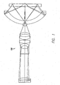
- FIG. 1 A representative illustration of a catadioptric design 100 in accordance with the teachings of the '518 patent is presented in FIG. 1 , which is similar to FIG. 1 of the '518 patent.
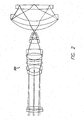
- FIG. 2 A representative illustration of a catadioptric design 200 in accordance with the teachings of the '638 patent is presented in FIG. 2 , which has similarities to FIG. 4 of the '638 patent.
- U.S. Patent 5,717,518 to Shafer et al discloses a dry objective design capable of high NA, ultra broadband UV imaging.
- the high NA (up to approximately 0.9) system can be used for broadband bright field and multiple wavelength dark-field imaging.
- the field lens group may need to be physically located within a central hole in the large curved catadioptric element, which can make manufacturing difficult and expensive.
- the field lens elements in such a design may require at least one glued interface. In the presence of wavelengths less then 365nm, reliable glues that can withstand light intensity levels at an internal focus are generally unavailable.
- the lens elements in such a design may be located very close to a field plane, thereby requiring a high degree of, or nearly perfect, surface quality and bulk material quality to prevent image degradation.
- element diameters are typically larger than a standard microscope objective, especially for the catadioptric group. Large diameter elements prevent integration into a standard microscope system.
- the dry objective design of FIG. 2 is generally capable of high NA, ultra broadband UV imaging.
- the design is a high NA (up to approximately 0.9) imaging system that can be used for broadband bright field and multiple wavelength dark-field imaging and can use a varifocal tube lens to provide a large range of magnifications.
- the FIG. 2 design introduces very tight tolerances in the field lens group, due in part to increased on-axis spherical aberration produced by the catadioptric group. This on-axis spherical aberration must be corrected by the following refractive lens elements.
- the design of FIG. 2 is relatively large, thereby generally requiring complicated optomechanical mounting of elements, especially in the catadioptric group.
- NA the NA of an objective represents the objective's ability to collect light and resolve fine specimen detail at a fixed object distance.
- Numerical aperture is measured as the sine of the vertex angle of the largest cone of meridional rays that can enter or leave the optical system or element, multiplied by the refractive index of the medium in which the vertex of the cone is located.
- a large numerical aperture provides distinct advantages during inspection, not the least of which is an ability to resolve smaller features of the specimen.
- high NAs collect a larger scattering angle, thereby improving performance in darkfield environments. For this reason, immersion objectives with high NAs are very desirable, and it is typically beneficial to specify the immersion substance refractive index when determining the operating NA of the objective. Changing the immersion substance to one having a higher refractive index will proportionally increase the NA.
- An objective that can cover as large a range of wavelengths as possible is also desirable in certain scenarios, particularly when using an arc lamp as an illumination source.
- Currently available immersion designs are all refractive, and refractive designs tend to limit wavelength range because few glass materials having high transmission below 400nm are effective for chromatic correction.
- Small objectives are also desirable, as small objectives can be used in combination with standard microscope objectives and physically fit within standard microscope turrets.
- the standard objective flange-to-object distance is in the range of 45mm.
- the available catadioptric objectives frequently cannot satisfy this requirement, so special microscope systems can be employed having an objective flange-to-object distance in excess of 60 mm and having lens diameters greater than 60 mm.
- An objective having low intrinsic aberrations is also desirable, as is an objective that is largely self-corrected for both monochromatic and chromatic aberrations.
- a self corrected objective will have looser alignment tolerances with other self corrected imaging optics.
- An objective with loose manufacturing tolerances, such as lens centering tolerances, may be particularly beneficial. Further, reducing incidence angles on lens surfaces can have a large effect on optical coating performance and manufacturing. In general, lower angles of incidence on lens surfaces also produce looser manufacturing tolerances.
- the present design presents a catadioptric immersion objective corrected over a wide wavelength range using a single glass material, or in certain circumstances, more than one glass material to improve performance.
- the objective employed herein may provide particular benefits in the microscopy field.
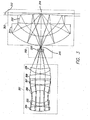
- One comparative aspect of the objective design is shown in FIG. 3 .
- the catadioptric objective as shown in FIG. 3 is optimized for broad-band imaging in the UV and visible spectral region, namely approximately 0.266 to 0.436 micron wavelengths.
- the objective provides high numerical apertures of 0.95 assuming pure water is used as an immersion substance. Other immersion substances could be used with higher indices to further increase the NA.
- the inventive design presented uses the Schupmann principle in combination with an Offner field lens to correct for axial color and first order lateral color.
- the field lens group 302 is slightly displaced from the intermediate image 315 to obtain enhanced performance, and the design employs liquid as shown by immersion liquid layer 313.
- immersion liquid As used herein, the terms “immersion liquid,” “immersion substance,” or “immersion liquid layer” refer to any non-solid non-gaseous substance, including but not limited to liquid or other viscous material, as particularly differentiated from gasses or gaseous materials. Immersion liquids that may be employed in the current design include, but are not limited to, water, oil, silicone gel, or other liquid, semi-liquid, viscous, or partially viscous substances. While solid, gaseous, or other materials may be included within the “immersion liquid” or “immersion substance,” as used herein, these materials comprise primarily liquid, semi-liquid, viscous, or partially viscous substances. These terms will be used throughout this discussion primarily using the term “immersion liquid,” but use of the other terms such as immersion substance or immersion liquid layer indicates materials conforming to the definition presented herein.
- the catadioptric group 303 or Mangin mirror arrangement includes a Mangin mirror element 312.
- Mangin mirror element 312 is a reflectively coated lens element.
- the catadioptric group 303 also includes concave spherical reflector 311, also a reflectively coated lens element. Both elements in the catadioptric group 303 have central optical apertures where reflective material is absent.
- the absence of reflective material allows light to pass from the object or specimen 314 through the immersion liquid 313 to Mangin mirror element 312, reflect from the second or outer surface of concave spherical reflector 311, onto the reflective surface of Mangin mirror element 312, and through concave spherical reflector 311 to form an intermediate image 315 after concave spherical reflector 311.
- the field lens group 302 may comprise one or more lenses, and in the aspect shown in FIG. 3 , one field lens 310 is employed.
- the focusing lens group 301 uses multiple lens elements, in the aspect shown six lens elements 304, 305, 306, 307, 308, and 309. All lenses in the focusing lens group 301 may be formed from a single type of material to collect the light from the field lens group 302 and the intermediate image 315.
- the lens prescription for this comparative example illustrated in FIG. 3 is presented in Table 1.
- Table 1 Prescription for lenses for the design of FIG. 3 Surf Radius Thickness Glass Diameter OBJ Infinity Infinity 0.00 1 Infinity 18.0000 9.10 STO Infinity -18.0000 8.50 3 17.6779 2.0000 Fused Silica 9.08 4 -44.7675 0.5000 8.85 5 13.6362 1.2500 Fused Silica 8.33 6 5.9607 5.6987 7.45 7 -6.5395 2.3911 Fused Silica 7.54 8 -12.2563 0.5000 8.78 9 29.8365 2.0000 Fused Silica 9.28 10 -21.5455 0.5000 9.40 11 -101.8361 2.0000 Fused Silica 9.34 12 -24.8901 0.5000 9.32 13 6.7391 2.2500 Fused Silica 8.81 14 22.9759 7.8495 8.19 15 1.9529 1.2495 Fused Silica 2.50 16 6.1579 0.7828 1.66 17 Infinity 0.9995 0.00 18 18.1935 4.1697 Fused Silica 26.20 19 12.
- the numbers in the leftmost column of Table 1 represent the surface number counting surfaces from the left of FIG. 3 .
- the left surface of lens 304 in the orientation presented in FIG. 3 (surface 3 in Table 1) has a radius of curvature of 17.6779 mm, a thickness of 2.0 mm, and the rightmost surface (surface 4) has a radius of curvature of -44.7675mm, and is 0.5mm from the next surface.
- the material used is fused silica, and surface 3 has a diameter of 9.08 mm while surface 4 has a diameter of 8.85 mm.
- the numerical aperture may approach or even exceed approximately 0.95 in water.
- the focusing lens group 301 has the ability to receive light energy and transmit focused light energy.
- the field lens group 302 has the ability to receive the focused light energy and provide intermediate light energy, and form intermediate image 315.
- the catadioptric group or Mangin mirror arrangement 303 receives the intermediate energy and provides controlled light energy to the specimen. Alternately, the reflected path originates at the specimen, and light reflected from the specimen is received by the catadioptric group or Mangin mirror arrangement 303 and forms and.transmits reflected light energy.
- the field lens group 302 receives the reflected light energy and transmitting resultant light energy, and the focusing lens group receives resultant light energy and transmits focused resultant light energy.
- An aperture or mask can be placed at the aperture stop (not shown) to limit or modify the NA of the objective.
- fused silica uses a single glass material, fused silica.
- Other materials may be employed, but it is noted that fused silica or any material used within the design may require low absorption over the range of wavelengths supported by the objective design.
- Fused silica offers relatively high transmission properties for light energy from 190 nm through the infrared wavelengths.
- fused silica can enable the design to be re-optimized for any center wavelength in this wavelength range.
- the design can be optimized for use with lasers at 193, 198.5 213, 244, 248, 257, 266, 308, 325, 351, 355, or 364nm.
- the design can also be optimally employed to cover lamp spectral bands from 190-202, 210-220, 230-254, 285-320, and 365-546nm.
- the design can be employed with an excimer laser at 157 nm or excimer lamps at 157 or 177nm. Re-optimization requires slight tuning or altering of components, and may generally be within the abilities of those skilled in the art. Calcium fluoride lenses may also be employed in the field lens group to increase the bandwidth of the objective.
- the maximum diameter of a lens element is 26 millimeters, which is significantly smaller than many objective designs previously employed in this wavelength range.
- the small size of this objective is particularly beneficial in view of the performance characteristics of the objective.
- the objective can be mounted in a standard microscope turret with an approximate 45mm flange-to-object separation.
- This immersion objective supports a numerical aperture of approximately 0.95, a field size of approximately 0.15 mm, has a corrected bandwidth from approximately 266-436 nm, and a polychromatic wavefront error of less than approximately 0.05 waves, levels which had been previously unachievable in combination in a single design.
- Field size in this arrangement represents the size of the area on the specimen that can be imaged the system with minimum degradation in optical performance.
- the comparative design of FIG. 3 provides a relatively low intrinsic polychromatic wavefront aberration over the design bandwidth from approximately 266-436nm.
- the low wavefront aberration provides increased manufacturing headroom, or ease of manufacture, while enabling relatively high performance of the manufactured objective.
- the design is also self corrected, where self corrected in this context means that the objective does not require any additional optical components to correct aberrations in order to achieve inspection design specifications. In other words, no additional components are needed to provide a generally aberration free image, or the objective provides substantially complete images without need for additional compensation.
- the ability to self correct can provide for simpler optical testing metrology and optical alignment to other self corrected imaging optics. Further correction of residual aberrations using additional imaging optics is also possible, where further correction can increase the optical specifications, including but not limited to bandwidth or field size.
- the design of FIG. 3 has relatively loose tolerances on the refractive index of the glass material, largely due to use of a single material that does not rely on the refractive index difference of two different glass materials to compensate for chromatic aberrations. Use of a single material also makes the design very insensitive to temperature changes. Previous designs have used multiple glass materials with different refractive index profiles for color correction. The result is the refractive index profile for each material changing differently with temperature, thereby changing the chromatic correction for temperatures other than the design temperature and reduced overall performance.
- the immersion objective design presented herein can support various modes of illumination and imaging. Modes supported can include bright field and a variety of dark field illumination and imaging modes. Other modes such as confocal, differential interference contrast, polarization contrast may also be supported using the present design.
- Bright field mode is commonly used in microscope systems.
- the advantage of bright field illumination is the clarity of the image produced.
- Using bright field illumination with an objective such as that presented herein provides a relatively accurate representation of object feature size multiplied by the magnification of the optical system.
- the objective and optical components presented herein can be readily used with image comparison and processing algorithms for computerized object detection and classification.
- Bright field mode typically uses a broad band incoherent light source, but it may be possible to use laser illumination sources with slightly modified illumination system components and employing the objective design presented herein.
- the confocal mode has been used for optical sectioning to resolve height differences of object features. Most imaging modes have difficulty detecting changes in the height of features.
- the confocal mode forms separate images of object features at each height of interest. Comparison of the images then shows the relative heights of different features. Confocal mode may be employed using the design presented herein.
- Dark field mode has been used to detect features on objects.
- the advantage of the dark field mode is that flat specular areas scatter very little light toward the detector, resulting in a dark image. Surface features or objects protruding above the object tend to scatter light toward the detector.
- dark field imaging produces an image of features, particles, or other irregularities on a dark background.
- the present design may be employed with dark field mode illumination. Dark field mode provides a large resultant signal upon striking small features that scatter light. This large resultant signal allows larger pixels to be employed for a given feature size, permitting faster object inspections. Fourier filtering can also be used to minimize the repeating pattern signal and enhance the defect signal to noise ratio during dark field inspection.
- dark field modes each including a specific illumination and collection scheme. Illumination and collection schemes can be chosen such that the scattered and diffracted light collected from the object provides an acceptable signal-to-noise ratio.
- Certain optical systems use different dark field imaging modes including ring dark field, laser directional dark field, double dark field, and central dark ground. Each of these dark field imaging modes may be employed in the present design.
- any of the above mentioned imaging modes may be efficiently employed with the immersion imaging design of FIG. 3 , albeit where slight modifications to certain components may offer improvements to certain performance parameters.
- the immersion imaging objective design presented enables inspection in any of the named imaging modes with the result of a relatively high numerical aperture, operation over a broad wavelength spectrum, with relatively high field size.
- the design can operate within a standard microscope turret and offers imaging performance better than that previously known.
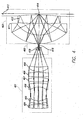
- FIG. 4 An alternate comparative aspect of the present design presents an immersion objective with nine separate elements. This aspect of the design is presented in FIG. 4 .
- the differences between the design of FIG. 4 and that of FIG. 3 are the reoptimization to correct for the refractive index and dispersion of water used as the immersion fluid.
- the design of FIG. 4 also increases the NA of the objective to approximately 1.0 assuming pure water is used as an immersion substance. Other immersion substances could be used with higher refractive indices to further increase the NA.
- the objective of the design of FIG. 4 is corrected over a bandwidth from approximately 266 to 436 nm has a field size of approximately 0.150 mm.
- the worst case polychromatic wavefront error for the FIG. 4 design is approximately 0.05 waves.
- the catadioptric group 403 includes a Mangin mirror element 412, which is a reflectively coated lens element, and a concave spherical reflector 411, which is also a reflectively coated lens element. Both Mangin mirror element 412 and concave spherical reflector 411 have central optical apertures where reflective material is absent.
- Field lens group 402 comprises a single field lens 410 in this aspect of the design.
- the focusing lens group 401 employs multiple lens elements, in this aspect the six lens elements 404,405,406,407,408, and 409, which may all be formed from a single type of material.
- the focusing lens group 401 collects light from the field lens group 402, including the intermediate image 415.
- An aperture or mask can be placed at the aperture stop (not shown) to limit or modify the NA of the objective.
- the design presented in FIG. 4 has virtually all of the advantages and flexibility described with respect to the design of FIG. 3 .
- the lens prescription for this comparative example is shown in Table 2. Table 2. Prescription for lenses for the design of FIG.
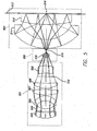
- FIG. 5 An alternate comparative aspect of the present design presents an immersion objective again having nine elements.
- This aspect of the design is presented in FIG. 5 .
- the main difference between the design of FIG. 5 and that of FIG. 3 is the redesign for a shorter wavelength while maintaining a relatively high 1.0 numerical aperture assuming pure water is used as an immersion substance. Other immersion substances could be used with higher refractive indices to further increase the NA.
- the objective of the design of FIG. 5 is corrected over a bandwidth from approximately 190 to 196 nm and has a field size of approximately 0.150 mm.
- the worst case polychromatic wavefront error for the FIG. 5 design is approximately 0.04 waves.
- the catadioptric group 503 includes a Mangin mirror element 512, again a reflectively coated lens element, and a concave spherical reflector 511, which is also a reflectively coated lens element. Both Mangin mirror element 512 and concave spherical reflector 511 have central optical apertures where reflective material is absent.
- the absence of reflective material, in the center of the components shown, allows light to pass from the object or specimen 514 through the immersion fluid 513 to Mangin mirror element 512, reflect from the second surface of concave spherical reflector 511 onto the Mangin mirror element 512, and transmit through concave spherical reflector 511 to form an intermediate image 515 after concave spherical reflector 511.
- the field lens group 502 comprises a single field lens 510 in this aspect of the design.
- the focusing lens group 501 employs multiple lens elements, in this aspect the six lens elements 504, 505, 506, 507, 508, and 509, which may all be formed from a single type of material.
- the focusing lens group 501 collects light from the field lens group 502, including the intermediate image 515.
- An aperture or mask can be placed at this aperture stop 516 to limit or modify the NA of the objective.
- the design presented in FIG. 5 generally offers the same advantages and flexibility described with respect to the design of FIG. 3 .
- the lens prescription for this comparative example is shown in Table 3. Table 3. Prescription for lenses for the design of FIG.
- FIG. 6 Another comparative aspect of the design presents an immersion objective having ten elements.
- This aspect of the design is presented in FIG. 6 .
- One difference between the design of FIG. 6 and that of FIG. 4 is the addition of a small immersion lens in front of the catadioptric group.
- the immersion liquid 614 is located to the right of lens 613.
- the objective of the design of FIG. 6 is corrected over a bandwidth from between approximately 266 to 436 nm, and has a field size of approximately 0.075 mm.
- the design of FIG. 6 again provides a relatively high approximately 1.2 numerical aperture assuming pure water is used as an immersion substance. Again, other immersion substances could be used with higher refractive indices to further increase the NA. Worst case polychromatic wavefront error for the FIG. 6 design is approximately 0.045 waves.
- the catadioptric group 603 includes an immersion lens 613, Mangin mirror element 612, which is a reflectively coated lens element, and a concave spherical reflector 611, also a reflectively coated lens element. Both Mangin mirror element 612 and concave spherical reflector 611 have central optical apertures where reflective material is absent.
- Field lens group 602 comprises a single field lens 610 in this aspect of the design. Note that borders for immersion liquid 614 are not specifically shown in this view; it is understood that immersion liquid 614 contacts immersion lens 613 and may be disposed adjacent to the surface of the specimen, not shown in this view.
- the focusing lens group 601 employs multiple lens elements, in this aspect the six lens elements 604, 605, 606, 607, 608, and 609, which may all be formed from a single type of material.
- the focusing lens group 601 collects light from the field lens group 602, including the intermediate image 615.
- An aperture or mask can be placed at the aperture stop (not shown) to limit or modify the NA of the objective.
- the lens prescription for this comparative example is shown in Table 4.
- Table 4. Prescription for lenses for the design of FIG. 6 Surf Radius Thickness Glass Diameter OBJ Infinity Infinity 0.0 1 Infinity 21.0000 8.9 STO Infinity -21.0000 8.5 3 33.3993 2.0000 Fused silica 8.9 4 -15.0280 0.5000 8.8 5 14.6458 1.5000 Fused silica 8.0 6 5.6019 4.7962 7.0 7 -5.0202 2.4398 Fused silica 6.9 8 -9.5561 0.5000 8.4 9 31.6324 2.0000 Fused silica 9.0 10 -19.8335 0.5000 9.2 11 36.6869 2.0000 Fused silica 9.2 12 -312.7053 0.5000 9.0 13 5.5701 2.2500 Fused silica 8.6 14 13.6079 8.0205 8.0205 8.0 8.0 15 1.3437 1.2495 Fused silica 1.7 16 2.2515 1.4000 0.7 17 Infinity 0.9995 2.0 18 20.3068 3.3979 Fused silica 3
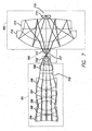
- An embodiment of the present design presents an immersion objective with eleven separate elements.
- This aspect of the design is presented in FIG. 7 .
- the difference between the design of FIG. 6 and that of FIG. 7 is the addition of a second field lens element, thus providing two field lens elements 710 and 711.
- the use of two field lens elements allows the immersion objective of the design of FIG. 7 to be corrected over a significantly wider bandwidth range, namely for bandwidths from approximately 266 to 800 nm.
- the objective of FIG. 7 provides a field size of approximately 0.100 mm and maintains the high approximately 1.1 numerical aperture assuming pure water is used as an immersion substance. Other immersion substances could be used with higher refractive indices to further increase the NA.
- the worst case polychromatic wavefront error for the FIG. 7 design is approximately 0.06 waves.
- the catadioptric group 703 includes an immersion lens 714, Mangin mirror element 713, which is a reflectively coated lens element, and a concave spherical reflector 712, which is also a reflectively coated lens element. Both Mangin mirror element 713 and concave spherical reflector 712 have central optical apertures where reflective material is absent.
- Field lens group 702 comprises two field lenses 710 and 711 in this aspect of the design, and again, borders for the immersion liquid or immersion substance 715 are not illustrated in this view.
- the focusing lens group 701 employs multiple lens elements, in this aspect the six lens elements 704, 705, 706, 707, 708, and 709, which may all be formed from a single type of material.
- the focusing lens group 701 collects light from the field lens group 702, including the intermediate image 717.
- An aperture or mask can be placed at the aperture stop 718 to limit or modify the NA of the objective.
- the design presented in FIG. 7 has the advantages and flexibility described with respect to the design of FIG. 3 .
- the lens prescription for this embodiment is shown in Table 5. Table 5. Prescription for lenses for the design of FIG. 7 Surf.
- Still another comparative aspect of the present design presents an immersion objective with eight separate elements.
- This aspect of the design is presented in FIG. 8 .
- the differences between the design of FIG. 8 and that of FIGs. 6 and 7 are a different catadioptric arrangement, fewer lens elements, and different correction wavelength, allowing the immersion objective to be corrected over a bandwidth from approximately 190 to 198 nm and simultaneously provide a field size of approximately 0.050 mm.
- the design of FIG. 8 maintains the high approximately 1.2 numerical aperture assuming pure water is used as an immersion substance, and other immersion substances could be used with higher refractive indices to further increase the NA.
- the worst case polychromatic wavefront error for the FIG. 8 design is approximately 0.05 waves.
- the catadioptric group 803 includes an immersion lens element 811, a Mangin mirror element 810, which is a reflectively coated lens element, and a concave spherical reflector 809, which is also a reflectively coated lens element.
- Mangin mirror element 810 has a central optical aperture where reflective material is absent.
- Concave spherical reflector 809 has a physical hole in the center of the element.
- Field lens group 802 comprises one field lens 808 in this aspect of the design.
- the focusing lens group 801 employs multiple lens elements, in this aspect the four lens elements 804, 805, 806, and 807, which may all be formed from a single type of material.
- the focusing lens group 801 collects light from the field lens group 802, including the intermediate image 814.
- An aperture or mask can be placed at the aperture stop 815 to limit or modify the NA of the objective.
- the design presented in FIG. 8 has the advantages and flexibility described with respect to the design of FIG. 3 .
- the lens prescription for this comparative example is shown in Table 6. Table 6. Prescription for lenses for the design of FIG.
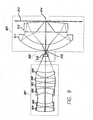
- An alternate comparative aspect of the present design employs a cover glass over the specimen and the associated objective corrects for the nominal thickness cover glass.
- An objective used for imaging purposes may be altered or reoptimized when using a cover glass, or alternately when using a cover glass in combination with an immersion liquid. Use of a cover glass may be particularly beneficial during inspection of biological materials.
- This comparative aspect of the design is presented in FIG. 9 .
- the objective illustrated is optimized for a nominal cover glass thickness of 0.17 mm and is corrected over a bandwidth from approximately 266 to 436 nm, with a field size of approximately 0.150 mm.
- the design of FIG. 9 maintains the high approximately 0.9 numerical aperture. Worst case polychromatic wavefront error for the FIG. 9 design is approximately 0.04 waves.
- the catadioptric group 903 includes a Mangin mirror element 912, a reflectively coated lens element, and concave spherical reflector 911, also a reflectively coated lens element.
- Mangin mirror elements 911 and 912 have central optical apertures free of reflective material. The absence of reflective material from elements 911 and 912 allows light to pass from the object or specimen 914, borders not shown, through cover glass 913, through Mangin mirror element 912, reflect from the second surface of concave spherical reflector 911 onto the Mangin mirror element 912, and transmit through concave spherical reflector 911 to form an intermediate image 915 in proximity to concave spherical reflector 911 and field lens group 902.
- Field lens group 902 comprises one field lens 910 in this aspect of the design.
- the focusing lens group 901 employs multiple lens elements, in this aspect the six lens elements 904, 905, 906, 907, 908, and 909, which may all be formed from a single type of material.
- the focusing lens group 901 collects light from the field lens group 902, including the intermediate image 915.
- An aperture or mask can be placed at the aperture stop (not shown) to limit or modify the NA of the objective.
- the design presented in FIG. 9 again has the advantages and flexibility described with respect to the design of FIG. 3 .
- the lens prescription for this comparative example is shown in Table 7. Table 7. Prescription for lenses for the design of FIG.
- the actual thickness of cover glass may vary from the nominal value of 0.17 mm. Effective imaging suggests that the cover glass thickness may vary over a range of ⁇ 0.020mm from the nominal and still employ an objective similar to that shown.
- the system may compensate for changes in the thickness of the cover glass by adjusting the spacing between the focusing lens group 901, the field lens group 902, and the catadioptric group 903. Table 8 summarizes the compensation. Table 8. Compensation for variations in the cover glass thickness of the design in FIG 9.
- the change in distance separation between the focusing lens group and the field lens group can be made twice the change of the separation between the field lens group and catadioptric group with only a small performance penalty.
- This technique of adjusting the air gaps between the focusing lens group, field lens group, and catadioptric group can also compensate for variations in the refractive index of the immersion fluid used in the designs of FIGs 3-8 .
- An alternate comparative aspect of the present design presents a self corrected varifocal imaging optics system having five elements and being corrected over a wavelength range from 266-800 nm using two glass materials, fused silica and calcium fluoride.
- One aspect of such an objective design is shown in FIG. 10 .
- This optical system can produce variable focal lengths from 200 mm to as large as desired. The only limitation is the total length of the system.
- the varifocal optics include a fixed focusing group 1001 and a moving imaging group 1002.
- the fixed focusing group 1001 is located a desired distance from the objective exit pupil 1003. Here, this separation distance is set to 100 mm.
- a 100 mm separation distance allows for insertion of beam splitters, phase plates, or filters between the objective and varifocal optics.
- the fixed focusing group 1001 includes two lenses 1004 and 1005.
- the moving imaging group 1002 includes three lens elements 1006, 1007, and 1008.
- the lens prescription for the optics illustrated in FIG. 10 is presented in Table 9. Table 9.
- Table 9 Prescription for lenses for the design of FIG. 10 Surf Radius Thickness Glass Diameter OBJ Infinity Infinity 0.00 STO Infinity 100.0000 8.10 2 51.6824 4.5000 Calcium fluoride 11.00 3 -22.5040 0.1000 10.84 4 -22.7121 3.0000 Fused silica 10.81 5 Infinity 102.1114 10.67 6 25.2044 3.0000 Fused silica 5.09 7 28.1765 2.0000 4.79 8 -31.3982 3.0000 Calcium fluoride 4.66 9 8.2051 1.5000 4.65 10 9.2578 3.0000 Fused silica 5.07 11 37.0927 25.0000 5.05 12 Infinity 1.0000 Fused silica 6.41 13 Infinity 1.0000 6.45 IMA Infinity 6.51
- Total focal length of the system may be altered by changing the focal length of either the focusing group 1001 or the imaging group 1002.
- Increasing the focal length of the focusing group 1001 will increase the thickness of Surface 11 at the smallest desired focal length.
- Increasing the focal length of the focusing group 1001 will concurrently increase the thickness of Surface 11 at the largest desired focal length.
- Modification of the distance between the imaging group 1002 and the fixed focusing group 1001 changes the focal length of the varifocal optics.
- Window 1009 is typically fixed to the front of the detector to protect the detector and limit photocontamination.
- the focal length of the varifocal optics and the distances change according to Table 10.
- Table 10. Lens group position and focal length changes for the design of FIG. 10 EFFL Magnification using 4.5mm focal length objective Thickness of Surface 5 Thickness of Surface 11 (Focal Length, mm) (mm) (mm) 225 50X 102.11 25.00 450 100X 89.27 100 900 200X 82.89 250 1800 400X 79.69 555 3600 800X 78.01 1250
- the distance between the focusing group 1002 and the detector 1010 may be achieved by using movable mirrors or by moving the detector 1010.
- Moving the detector 1010 may be easiest when small focal lengths are desired. However, with large focal lengths, the necessary distance can increase rapidly. In the presence of a rapidly increasing distance, use of moving mirrors reduces the space required for refocusing.
- Figure four or “trombone mirror” geometries can assist in space reduction and providing effective inspection using the objectives presented.
- One possible comparative "figure four" geometry is shown in FIG. 11 .
- Light first enters fixed focusing group 1101, comprising lenses 1101a and 1101b, and is focused to imaging group 1102, comprising lenses 1102a, 1102b, and 1102c.
- Imaging group 1102 comprising lenses 1102a, 1102b, and 1102c.
- Light reflects off reflective surfaces or mirrors 1103 and 1104 before reaching detector 1105.
- the positions of mirrors 1103 and 1104 can be changed to increase or decrease the distance from imaging lens group 1102 to fixed detector 1105. This effectively brings the image into focus.
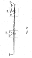
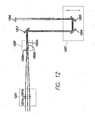
- a "trombone geometry” may also be employed, and one possible comparative design is shown in FIG. 12 .
- Light enters fixed focusing group 1201, including lenses 1201a and 1201b, and is focused to imaging group 1202, comprising lenses 1202a, 1202b, and 1202c.
- Imaging group 1202 comprising lenses 1202a, 1202b, and 1202c.
- Light then reflects from mirrors 1203, 1204, and 1205 before reaching detector 1206.
- the position of mirror group 1207 which in this example is composed of mirrors 1204 and 1205, can be changed to increase or decrease the distance from imaging lens group 1202 to fixed detector 1206. The effect of this aspect of the design is to more adequately bring the image into focus.
- the varifocal optics described in this comparative example can be of the same design as presented in Table 9.
- the moving mirrors only serve to adjust the air space between lens group 1202 and the detector.
- the air space between the lens group 1202 and the detector can be adjusted according to the values in Table 10.
- the present system design may be employed in various environments, including but not limited to lithography, microscopy, biological inspection, medical research, and the like.
Landscapes
- Physics & Mathematics (AREA)
- General Physics & Mathematics (AREA)
- Optics & Photonics (AREA)
- Chemical & Material Sciences (AREA)
- Analytical Chemistry (AREA)
- Lenses (AREA)
- Microscoopes, Condenser (AREA)
Applications Claiming Priority (2)
| Application Number | Priority Date | Filing Date | Title |
|---|---|---|---|
| US10/812,111 US7307783B2 (en) | 2003-02-21 | 2004-03-29 | Catadioptric imaging system employing immersion liquid for use in broad band microscopy |
| PCT/US2005/010322 WO2005094304A2 (en) | 2004-03-29 | 2005-03-28 | Catadioptric imaging system employing immersion liquid for use in broad band microscopy |
Publications (3)
| Publication Number | Publication Date |
|---|---|
| EP1749230A2 EP1749230A2 (en) | 2007-02-07 |
| EP1749230A4 EP1749230A4 (en) | 2008-04-02 |
| EP1749230B1 true EP1749230B1 (en) | 2015-06-03 |
Family
ID=35064278
Family Applications (1)
| Application Number | Title | Priority Date | Filing Date |
|---|---|---|---|
| EP05731783.6A Expired - Fee Related EP1749230B1 (en) | 2004-03-29 | 2005-03-28 | Catadioptric imaging system employing immersion liquid for use in broad band microscopy, and corresponding method |
Country Status (4)
| Country | Link |
|---|---|
| US (2) | US7307783B2 (ja) |
| EP (1) | EP1749230B1 (ja) |
| JP (1) | JP5172328B2 (ja) |
| WO (1) | WO2005094304A2 (ja) |
Families Citing this family (22)
| Publication number | Priority date | Publication date | Assignee | Title |
|---|---|---|---|---|
| JP4133319B2 (ja) | 2000-07-14 | 2008-08-13 | ノバダック テクノロジーズ インコーポレイテッド | コンパクトな蛍光内視鏡映像システム |
| US20060241496A1 (en) | 2002-01-15 | 2006-10-26 | Xillix Technologies Corp. | Filter for use with imaging endoscopes |
| US7884998B2 (en) * | 2003-02-21 | 2011-02-08 | Kla - Tencor Corporation | Catadioptric microscope objective employing immersion liquid for use in broad band microscopy |
| US7957066B2 (en) * | 2003-02-21 | 2011-06-07 | Kla-Tencor Corporation | Split field inspection system using small catadioptric objectives |
| WO2005081030A1 (en) * | 2004-02-18 | 2005-09-01 | Corning Incorporated | Catadioptric imaging system for high numerical aperture imaging with deep ultraviolet light |
| US20090303317A1 (en) * | 2006-02-07 | 2009-12-10 | Novadaq Technologies Inc. | Near infrared imaging |
| GB0625775D0 (en) | 2006-12-22 | 2007-02-07 | Isis Innovation | Focusing apparatus and method |
| EP2775349B1 (en) * | 2007-03-08 | 2021-08-11 | Cellavision AB | A method for determining an in-focus position and a vision inspection system |
| US8665536B2 (en) * | 2007-06-19 | 2014-03-04 | Kla-Tencor Corporation | External beam delivery system for laser dark-field illumination in a catadioptric optical system |
| US7633689B2 (en) | 2007-07-18 | 2009-12-15 | Asml Holding N.V. | Catadioptric optical system for scatterometry |
| US20090109416A1 (en) * | 2007-09-13 | 2009-04-30 | Applied Precision, Inc. | Dispersing immersion liquid for high resolution imaging and lithography |
| US9341831B2 (en) | 2011-06-10 | 2016-05-17 | Canon Kabushiki Kaisha | Optical system with catadioptric optical subsystem |
| DE102013112212B4 (de) * | 2013-11-06 | 2022-03-10 | Carl Zeiss Smt Gmbh | Optische Zoomeinrichtung, optische Abbildungseinrichtung, optisches Zoomverfahren und Abbildungsverfahren für die Mikroskopie |
| US10656098B2 (en) | 2016-02-03 | 2020-05-19 | Kla-Tencor Corporation | Wafer defect inspection and review systems |
| WO2017136286A1 (en) | 2016-02-03 | 2017-08-10 | Kla-Tencor Corporation | Wafer defect inspection and review systems |
| US10293122B2 (en) | 2016-03-17 | 2019-05-21 | Novadaq Technologies ULC | Endoluminal introducer with contamination avoidance |
| CN107505692B (zh) * | 2017-09-26 | 2020-04-10 | 张家港中贺自动化科技有限公司 | 一种折反射式物镜 |
| CN108254912B (zh) * | 2018-01-23 | 2020-03-27 | 电子科技大学 | 一种用于氮化物mocvd外延生长模式的实时显微监测系统 |
| CN108873289B (zh) | 2018-09-04 | 2024-02-09 | 中国科学院长春光学精密机械与物理研究所 | 显微物镜光学系统及光学设备 |
| CN109298517B (zh) * | 2018-11-05 | 2020-10-30 | 中国航空工业集团公司洛阳电光设备研究所 | 一种多光谱同轴折反式无焦光学系统 |
| US20230003987A1 (en) * | 2019-11-22 | 2023-01-05 | Howard Hughes Medical Institute | Catadioptric microscopy |
| US11561476B1 (en) * | 2021-07-10 | 2023-01-24 | Kenneth Carlisle Johnson | UV lithography system |
Citations (2)
| Publication number | Priority date | Publication date | Assignee | Title |
|---|---|---|---|---|
| US2801570A (en) * | 1952-05-29 | 1957-08-06 | Centre Nat Rech Scient | Mirror type optical objectives for microscopes |
| US6392793B1 (en) * | 1996-07-22 | 2002-05-21 | Kla-Tencor Corporation | High NA imaging system |
Family Cites Families (21)
| Publication number | Priority date | Publication date | Assignee | Title |
|---|---|---|---|---|
| JPS5510172B2 (ja) * | 1975-02-14 | 1980-03-14 | ||
| CH613597B (de) * | 1975-08-14 | Bbc Brown Boveri & Cie | Hinter einem frontglas eines zeitmessgeraetes angeordnete fluessigkristallanzeige. | |
| JPS62208016A (ja) * | 1986-03-07 | 1987-09-12 | Matsushita Electric Ind Co Ltd | テレビジヨン画像投写装置 |
| JPH043104A (ja) * | 1990-04-20 | 1992-01-08 | Dainippon Screen Mfg Co Ltd | 顕微鏡用対物レンズ |
| US5159495A (en) * | 1990-12-11 | 1992-10-27 | Eastman Kodak Company | Graded index optical elements and catadioptric optical systems |
| JPH06167653A (ja) * | 1992-11-27 | 1994-06-14 | Olympus Optical Co Ltd | 液浸油 |
| JPH06175034A (ja) * | 1992-12-10 | 1994-06-24 | Olympus Optical Co Ltd | 長作動距離対物レンズ |
| US6512631B2 (en) * | 1996-07-22 | 2003-01-28 | Kla-Tencor Corporation | Broad-band deep ultraviolet/vacuum ultraviolet catadioptric imaging system |
| JP3123457B2 (ja) * | 1996-05-13 | 2001-01-09 | 株式会社ニコン | 顕微鏡 |
| US5999310A (en) * | 1996-07-22 | 1999-12-07 | Shafer; David Ross | Ultra-broadband UV microscope imaging system with wide range zoom capability |
| US5717518A (en) * | 1996-07-22 | 1998-02-10 | Kla Instruments Corporation | Broad spectrum ultraviolet catadioptric imaging system |
| US6483638B1 (en) * | 1996-07-22 | 2002-11-19 | Kla-Tencor Corporation | Ultra-broadband UV microscope imaging system with wide range zoom capability |
| US5825043A (en) * | 1996-10-07 | 1998-10-20 | Nikon Precision Inc. | Focusing and tilting adjustment system for lithography aligner, manufacturing apparatus or inspection apparatus |
| JP2002082285A (ja) * | 2000-09-07 | 2002-03-22 | Nikon Corp | 反射屈折光学系および該光学系を備えた露光装置 |
| US7136159B2 (en) * | 2000-09-12 | 2006-11-14 | Kla-Tencor Technologies Corporation | Excimer laser inspection system |
| JP2003015046A (ja) * | 2001-06-28 | 2003-01-15 | Nikon Corp | 液浸系顕微鏡対物レンズ |
| JP2003029162A (ja) * | 2001-07-11 | 2003-01-29 | Nikon Corp | 顕微鏡用対物レンズおよび顕微鏡 |
| JP4066079B2 (ja) * | 2001-11-26 | 2008-03-26 | 株式会社ニコン | 対物レンズ及びそれを用いた光学装置 |
| TWI242691B (en) * | 2002-08-23 | 2005-11-01 | Nikon Corp | Projection optical system and method for photolithography and exposure apparatus and method using same |
| US8675276B2 (en) * | 2003-02-21 | 2014-03-18 | Kla-Tencor Corporation | Catadioptric imaging system for broad band microscopy |
| US7180658B2 (en) * | 2003-02-21 | 2007-02-20 | Kla-Tencor Technologies Corporation | High performance catadioptric imaging system |
-
2004
- 2004-03-29 US US10/812,111 patent/US7307783B2/en not_active Expired - Fee Related
-
2005
- 2005-03-28 WO PCT/US2005/010322 patent/WO2005094304A2/en active Search and Examination
- 2005-03-28 JP JP2007506429A patent/JP5172328B2/ja not_active Expired - Fee Related
- 2005-03-28 EP EP05731783.6A patent/EP1749230B1/en not_active Expired - Fee Related
-
2007
- 2007-12-05 US US11/999,558 patent/US7633675B2/en not_active Expired - Fee Related
Patent Citations (2)
| Publication number | Priority date | Publication date | Assignee | Title |
|---|---|---|---|---|
| US2801570A (en) * | 1952-05-29 | 1957-08-06 | Centre Nat Rech Scient | Mirror type optical objectives for microscopes |
| US6392793B1 (en) * | 1996-07-22 | 2002-05-21 | Kla-Tencor Corporation | High NA imaging system |
Non-Patent Citations (2)
| Title |
|---|
| "Lehrbuch der Experimentalphysik, volume III", 1 January 1974, WALTER DE GRUYTER, BERLIN, NEW YORK, article BERGMANN ET AL: "Lehrbuch der Experimentalphysik, volume III", pages: 101 - 102, XP055158501 * |
| "Lexikon der Physik", 1 January 1969, FRANCKH'SCHE VERLAGSHANDLUNG, STUTTGART, article "Lexikon der Physik", XP055158505 * |
Also Published As
| Publication number | Publication date |
|---|---|
| US20050152027A1 (en) | 2005-07-14 |
| EP1749230A4 (en) | 2008-04-02 |
| US7307783B2 (en) | 2007-12-11 |
| JP2007531060A (ja) | 2007-11-01 |
| WO2005094304A3 (en) | 2006-12-21 |
| JP5172328B2 (ja) | 2013-03-27 |
| US7633675B2 (en) | 2009-12-15 |
| WO2005094304A9 (en) | 2007-01-11 |
| US20080247035A1 (en) | 2008-10-09 |
| WO2005094304A2 (en) | 2005-10-13 |
| EP1749230A2 (en) | 2007-02-07 |
Similar Documents
| Publication | Publication Date | Title |
|---|---|---|
| EP1749230B1 (en) | Catadioptric imaging system employing immersion liquid for use in broad band microscopy, and corresponding method | |
| EP1664885B1 (en) | Catadioptric imaging system for broad band microscopy | |
| US7679842B2 (en) | High performance catadioptric imaging system | |
| US7884998B2 (en) | Catadioptric microscope objective employing immersion liquid for use in broad band microscopy | |
| EP1864177B1 (en) | Small ultra-high na catadioptric objective and system | |
| JP6140663B2 (ja) | 反射対物鏡、ミラーを有する広帯域対物光学系、及び屈折レンズを有する光学撮像システム、及び2つ以上の結像経路を有する広帯域光学撮像システム | |
| US7869121B2 (en) | Small ultra-high NA catadioptric objective using aspheric surfaces | |
| EP2187251B1 (en) | Small ultra-high NA catadioptric objective using a Mangin mirror |
Legal Events
| Date | Code | Title | Description |
|---|---|---|---|
| PUAI | Public reference made under article 153(3) epc to a published international application that has entered the european phase |
Free format text: ORIGINAL CODE: 0009012 |
|
| 17P | Request for examination filed |
Effective date: 20060927 |
|
| AK | Designated contracting states |
Kind code of ref document: A2 Designated state(s): AT BE BG CH CY CZ DE DK EE ES FI FR GB GR HU IE IS IT LI LT LU MC NL PL PT RO SE SI SK TR |
|
| AX | Request for extension of the european patent |
Extension state: AL BA HR LV MK YU |
|
| R17D | Deferred search report published (corrected) |
Effective date: 20070111 |
|
| DAX | Request for extension of the european patent (deleted) | ||
| RBV | Designated contracting states (corrected) |
Designated state(s): DE FR GB |
|
| RIC1 | Information provided on ipc code assigned before grant |
Ipc: G02B 21/33 20060101ALI20080221BHEP Ipc: G02B 21/04 20060101ALN20080221BHEP Ipc: G02B 17/08 20060101AFI20080221BHEP |
|
| A4 | Supplementary search report drawn up and despatched |
Effective date: 20080303 |
|
| 17Q | First examination report despatched |
Effective date: 20100416 |
|
| REG | Reference to a national code |
Ref country code: DE Ref legal event code: R079 Ref document number: 602005046684 Country of ref document: DE Free format text: PREVIOUS MAIN CLASS: G02B0017000000 Ipc: G02B0017080000 |
|
| GRAP | Despatch of communication of intention to grant a patent |
Free format text: ORIGINAL CODE: EPIDOSNIGR1 |
|
| RIC1 | Information provided on ipc code assigned before grant |
Ipc: G02B 21/33 20060101ALN20150106BHEP Ipc: G02B 17/08 20060101AFI20150106BHEP Ipc: G02B 21/04 20060101ALI20150106BHEP Ipc: G03F 7/20 20060101ALI20150106BHEP |
|
| INTG | Intention to grant announced |
Effective date: 20150119 |
|
| GRAS | Grant fee paid |
Free format text: ORIGINAL CODE: EPIDOSNIGR3 |
|
| GRAA | (expected) grant |
Free format text: ORIGINAL CODE: 0009210 |
|
| AK | Designated contracting states |
Kind code of ref document: B1 Designated state(s): DE FR GB |
|
| REG | Reference to a national code |
Ref country code: GB Ref legal event code: FG4D |
|
| REG | Reference to a national code |
Ref country code: DE Ref legal event code: R096 Ref document number: 602005046684 Country of ref document: DE |
|
| REG | Reference to a national code |
Ref country code: DE Ref legal event code: R097 Ref document number: 602005046684 Country of ref document: DE |
|
| PLBE | No opposition filed within time limit |
Free format text: ORIGINAL CODE: 0009261 |
|
| STAA | Information on the status of an ep patent application or granted ep patent |
Free format text: STATUS: NO OPPOSITION FILED WITHIN TIME LIMIT |
|
| 26N | No opposition filed |
Effective date: 20160304 |
|
| PGFP | Annual fee paid to national office [announced via postgrant information from national office to epo] |
Ref country code: DE Payment date: 20160331 Year of fee payment: 12 |
|
| GBPC | Gb: european patent ceased through non-payment of renewal fee |
Effective date: 20160328 |
|
| REG | Reference to a national code |
Ref country code: FR Ref legal event code: ST Effective date: 20161130 |
|
| PG25 | Lapsed in a contracting state [announced via postgrant information from national office to epo] |
Ref country code: FR Free format text: LAPSE BECAUSE OF NON-PAYMENT OF DUE FEES Effective date: 20160331 Ref country code: GB Free format text: LAPSE BECAUSE OF NON-PAYMENT OF DUE FEES Effective date: 20160328 |
|
| REG | Reference to a national code |
Ref country code: DE Ref legal event code: R119 Ref document number: 602005046684 Country of ref document: DE |
|
| PG25 | Lapsed in a contracting state [announced via postgrant information from national office to epo] |
Ref country code: DE Free format text: LAPSE BECAUSE OF NON-PAYMENT OF DUE FEES Effective date: 20171003 |
|
| P01 | Opt-out of the competence of the unified patent court (upc) registered |
Effective date: 20230525 |