EP1748306B1 - Support authentifiable, le même comme étiquette ou feuille de transfert, sur feuille ou support d'enregistrement d'informations - Google Patents
Support authentifiable, le même comme étiquette ou feuille de transfert, sur feuille ou support d'enregistrement d'informations Download PDFInfo
- Publication number
- EP1748306B1 EP1748306B1 EP05729183.3A EP05729183A EP1748306B1 EP 1748306 B1 EP1748306 B1 EP 1748306B1 EP 05729183 A EP05729183 A EP 05729183A EP 1748306 B1 EP1748306 B1 EP 1748306B1
- Authority
- EP
- European Patent Office
- Prior art keywords
- layer
- authentication medium
- light
- film
- authentication
- Prior art date
- Legal status (The legal status is an assumption and is not a legal conclusion. Google has not performed a legal analysis and makes no representation as to the accuracy of the status listed.)
- Active
Links
- 239000010410 layer Substances 0.000 claims description 438
- 239000000758 substrate Substances 0.000 claims description 109
- 239000000463 material Substances 0.000 claims description 56
- 239000012790 adhesive layer Substances 0.000 claims description 46
- 239000004988 Nematic liquid crystal Substances 0.000 claims description 34
- 239000010408 film Substances 0.000 description 111
- 239000004986 Cholesteric liquid crystals (ChLC) Substances 0.000 description 65
- 239000012071 phase Substances 0.000 description 62
- 229920005989 resin Polymers 0.000 description 59
- 239000011347 resin Substances 0.000 description 59
- 239000010409 thin film Substances 0.000 description 44
- 230000008859 change Effects 0.000 description 35
- 239000000203 mixture Substances 0.000 description 27
- 239000000243 solution Substances 0.000 description 26
- 238000000034 method Methods 0.000 description 23
- 229920002799 BoPET Polymers 0.000 description 18
- 239000000123 paper Substances 0.000 description 18
- 239000002904 solvent Substances 0.000 description 18
- UWCWUCKPEYNDNV-LBPRGKRZSA-N 2,6-dimethyl-n-[[(2s)-pyrrolidin-2-yl]methyl]aniline Chemical compound CC1=CC=CC(C)=C1NC[C@H]1NCCC1 UWCWUCKPEYNDNV-LBPRGKRZSA-N 0.000 description 17
- 229910052751 metal Inorganic materials 0.000 description 17
- 239000002184 metal Substances 0.000 description 17
- -1 polyethylene terephthalate Polymers 0.000 description 17
- 239000002985 plastic film Substances 0.000 description 16
- 238000007639 printing Methods 0.000 description 16
- YXFVVABEGXRONW-UHFFFAOYSA-N Toluene Chemical compound CC1=CC=CC=C1 YXFVVABEGXRONW-UHFFFAOYSA-N 0.000 description 15
- 239000003505 polymerization initiator Substances 0.000 description 13
- 239000011248 coating agent Substances 0.000 description 12
- 238000000576 coating method Methods 0.000 description 12
- 239000011241 protective layer Substances 0.000 description 12
- 230000005855 radiation Effects 0.000 description 12
- 239000004372 Polyvinyl alcohol Substances 0.000 description 11
- 230000005865 ionizing radiation Effects 0.000 description 11
- 229920002451 polyvinyl alcohol Polymers 0.000 description 11
- 229920002284 Cellulose triacetate Polymers 0.000 description 10
- NNLVGZFZQQXQNW-ADJNRHBOSA-N [(2r,3r,4s,5r,6s)-4,5-diacetyloxy-3-[(2s,3r,4s,5r,6r)-3,4,5-triacetyloxy-6-(acetyloxymethyl)oxan-2-yl]oxy-6-[(2r,3r,4s,5r,6s)-4,5,6-triacetyloxy-2-(acetyloxymethyl)oxan-3-yl]oxyoxan-2-yl]methyl acetate Chemical compound O([C@@H]1O[C@@H]([C@H]([C@H](OC(C)=O)[C@H]1OC(C)=O)O[C@H]1[C@@H]([C@@H](OC(C)=O)[C@H](OC(C)=O)[C@@H](COC(C)=O)O1)OC(C)=O)COC(=O)C)[C@@H]1[C@@H](COC(C)=O)O[C@@H](OC(C)=O)[C@H](OC(C)=O)[C@H]1OC(C)=O NNLVGZFZQQXQNW-ADJNRHBOSA-N 0.000 description 10
- 230000008901 benefit Effects 0.000 description 9
- 150000001875 compounds Chemical class 0.000 description 9
- 238000001035 drying Methods 0.000 description 9
- 229920006255 plastic film Polymers 0.000 description 9
- 238000010438 heat treatment Methods 0.000 description 8
- 229920001187 thermosetting polymer Polymers 0.000 description 8
- 239000004973 liquid crystal related substance Substances 0.000 description 7
- 238000004519 manufacturing process Methods 0.000 description 7
- 229920000139 polyethylene terephthalate Polymers 0.000 description 7
- 239000005020 polyethylene terephthalate Substances 0.000 description 7
- 229920005992 thermoplastic resin Polymers 0.000 description 7
- 239000004698 Polyethylene Substances 0.000 description 6
- 229910052782 aluminium Inorganic materials 0.000 description 6
- 239000000975 dye Substances 0.000 description 6
- 239000011295 pitch Substances 0.000 description 6
- 229920000573 polyethylene Polymers 0.000 description 6
- 238000007740 vapor deposition Methods 0.000 description 6
- 239000005083 Zinc sulfide Substances 0.000 description 5
- 230000015572 biosynthetic process Effects 0.000 description 5
- 239000002131 composite material Substances 0.000 description 5
- 238000002834 transmittance Methods 0.000 description 5
- 229910052984 zinc sulfide Inorganic materials 0.000 description 5
- OZAIFHULBGXAKX-UHFFFAOYSA-N 2-(2-cyanopropan-2-yldiazenyl)-2-methylpropanenitrile Chemical compound N#CC(C)(C)N=NC(C)(C)C#N OZAIFHULBGXAKX-UHFFFAOYSA-N 0.000 description 4
- KWOLFJPFCHCOCG-UHFFFAOYSA-N Acetophenone Chemical compound CC(=O)C1=CC=CC=C1 KWOLFJPFCHCOCG-UHFFFAOYSA-N 0.000 description 4
- 241001234580 Palio Species 0.000 description 4
- GWEVSGVZZGPLCZ-UHFFFAOYSA-N Titan oxide Chemical compound O=[Ti]=O GWEVSGVZZGPLCZ-UHFFFAOYSA-N 0.000 description 4
- 238000006243 chemical reaction Methods 0.000 description 4
- 229910052804 chromium Inorganic materials 0.000 description 4
- 238000004049 embossing Methods 0.000 description 4
- 230000002708 enhancing effect Effects 0.000 description 4
- 229910052737 gold Inorganic materials 0.000 description 4
- 229910052759 nickel Inorganic materials 0.000 description 4
- 239000000049 pigment Substances 0.000 description 4
- 229920003023 plastic Polymers 0.000 description 4
- 239000004033 plastic Substances 0.000 description 4
- 230000010287 polarization Effects 0.000 description 4
- 239000011342 resin composition Substances 0.000 description 4
- 229910052709 silver Inorganic materials 0.000 description 4
- 239000012780 transparent material Substances 0.000 description 4
- 229920006337 unsaturated polyester resin Polymers 0.000 description 4
- IMROMDMJAWUWLK-UHFFFAOYSA-N Ethenol Chemical compound OC=C IMROMDMJAWUWLK-UHFFFAOYSA-N 0.000 description 3
- 239000004743 Polypropylene Substances 0.000 description 3
- 239000004793 Polystyrene Substances 0.000 description 3
- 239000004820 Pressure-sensitive adhesive Substances 0.000 description 3
- CSNCPNFITVRIBQ-UHFFFAOYSA-N [6-[4-[4-(4-prop-2-enoyloxybutoxycarbonyloxy)benzoyl]oxybenzoyl]oxy-2,3,3a,5,6,6a-hexahydrofuro[3,2-b]furan-3-yl] 4-[4-(4-prop-2-enoyloxybutoxycarbonyloxy)benzoyl]oxybenzoate Chemical compound C1=CC(OC(=O)OCCCCOC(=O)C=C)=CC=C1C(=O)OC1=CC=C(C(=O)OC2C3OCC(C3OC2)OC(=O)C=2C=CC(OC(=O)C=3C=CC(OC(=O)OCCCCOC(=O)C=C)=CC=3)=CC=2)C=C1 CSNCPNFITVRIBQ-UHFFFAOYSA-N 0.000 description 3
- 230000003044 adaptive effect Effects 0.000 description 3
- 239000000853 adhesive Substances 0.000 description 3
- 230000001070 adhesive effect Effects 0.000 description 3
- PYKYMHQGRFAEBM-UHFFFAOYSA-N anthraquinone Natural products CCC(=O)c1c(O)c2C(=O)C3C(C=CC=C3O)C(=O)c2cc1CC(=O)OC PYKYMHQGRFAEBM-UHFFFAOYSA-N 0.000 description 3
- 150000004056 anthraquinones Chemical class 0.000 description 3
- 230000000712 assembly Effects 0.000 description 3
- 238000000429 assembly Methods 0.000 description 3
- 229910052797 bismuth Inorganic materials 0.000 description 3
- 239000011247 coating layer Substances 0.000 description 3
- 239000003086 colorant Substances 0.000 description 3
- 229920005994 diacetyl cellulose Polymers 0.000 description 3
- 230000000694 effects Effects 0.000 description 3
- 239000004744 fabric Substances 0.000 description 3
- 229910052738 indium Inorganic materials 0.000 description 3
- 229910052745 lead Inorganic materials 0.000 description 3
- 150000002739 metals Chemical class 0.000 description 3
- 125000002496 methyl group Chemical group [H]C([H])([H])* 0.000 description 3
- 239000000178 monomer Substances 0.000 description 3
- 238000007747 plating Methods 0.000 description 3
- 229920002492 poly(sulfone) Polymers 0.000 description 3
- 229920001230 polyarylate Polymers 0.000 description 3
- 229920000515 polycarbonate Polymers 0.000 description 3
- 239000004417 polycarbonate Substances 0.000 description 3
- 229920001721 polyimide Polymers 0.000 description 3
- 239000009719 polyimide resin Substances 0.000 description 3
- 238000006116 polymerization reaction Methods 0.000 description 3
- 229920001155 polypropylene Polymers 0.000 description 3
- 229920002223 polystyrene Polymers 0.000 description 3
- 238000004544 sputter deposition Methods 0.000 description 3
- 229920002803 thermoplastic polyurethane Polymers 0.000 description 3
- WFUGQJXVXHBTEM-UHFFFAOYSA-N 2-hydroperoxy-2-(2-hydroperoxybutan-2-ylperoxy)butane Chemical compound CCC(C)(OO)OOC(C)(CC)OO WFUGQJXVXHBTEM-UHFFFAOYSA-N 0.000 description 2
- HRPVXLWXLXDGHG-UHFFFAOYSA-N Acrylamide Chemical compound NC(=O)C=C HRPVXLWXLXDGHG-UHFFFAOYSA-N 0.000 description 2
- 239000004925 Acrylic resin Substances 0.000 description 2
- 229920000178 Acrylic resin Polymers 0.000 description 2
- 239000004342 Benzoyl peroxide Substances 0.000 description 2
- OMPJBNCRMGITSC-UHFFFAOYSA-N Benzoylperoxide Chemical compound C=1C=CC=CC=1C(=O)OOC(=O)C1=CC=CC=C1 OMPJBNCRMGITSC-UHFFFAOYSA-N 0.000 description 2
- UFHFLCQGNIYNRP-UHFFFAOYSA-N Hydrogen Chemical compound [H][H] UFHFLCQGNIYNRP-UHFFFAOYSA-N 0.000 description 2
- UQSXHKLRYXJYBZ-UHFFFAOYSA-N Iron oxide Chemical compound [Fe]=O UQSXHKLRYXJYBZ-UHFFFAOYSA-N 0.000 description 2
- 229930192627 Naphthoquinone Natural products 0.000 description 2
- 239000000020 Nitrocellulose Substances 0.000 description 2
- NIXOWILDQLNWCW-UHFFFAOYSA-N acrylic acid group Chemical group C(C=C)(=O)O NIXOWILDQLNWCW-UHFFFAOYSA-N 0.000 description 2
- 230000009471 action Effects 0.000 description 2
- 229920000180 alkyd Polymers 0.000 description 2
- 125000002947 alkylene group Chemical group 0.000 description 2
- 230000004075 alteration Effects 0.000 description 2
- 229910052787 antimony Inorganic materials 0.000 description 2
- 239000007864 aqueous solution Substances 0.000 description 2
- RWCCWEUUXYIKHB-UHFFFAOYSA-N benzophenone Chemical compound C=1C=CC=CC=1C(=O)C1=CC=CC=C1 RWCCWEUUXYIKHB-UHFFFAOYSA-N 0.000 description 2
- 239000012965 benzophenone Substances 0.000 description 2
- 235000019400 benzoyl peroxide Nutrition 0.000 description 2
- 239000011230 binding agent Substances 0.000 description 2
- QHIWVLPBUQWDMQ-UHFFFAOYSA-N butyl prop-2-enoate;methyl 2-methylprop-2-enoate;prop-2-enoic acid Chemical compound OC(=O)C=C.COC(=O)C(C)=C.CCCCOC(=O)C=C QHIWVLPBUQWDMQ-UHFFFAOYSA-N 0.000 description 2
- 229910052793 cadmium Inorganic materials 0.000 description 2
- 239000003054 catalyst Substances 0.000 description 2
- 230000003098 cholesteric effect Effects 0.000 description 2
- 239000011651 chromium Substances 0.000 description 2
- 239000008199 coating composition Substances 0.000 description 2
- 229910017052 cobalt Inorganic materials 0.000 description 2
- 239000010941 cobalt Substances 0.000 description 2
- GUTLYIVDDKVIGB-UHFFFAOYSA-N cobalt atom Chemical compound [Co] GUTLYIVDDKVIGB-UHFFFAOYSA-N 0.000 description 2
- 229910052802 copper Inorganic materials 0.000 description 2
- 239000013078 crystal Substances 0.000 description 2
- JHIVVAPYMSGYDF-UHFFFAOYSA-N cyclohexanone Chemical compound O=C1CCCCC1 JHIVVAPYMSGYDF-UHFFFAOYSA-N 0.000 description 2
- 230000001419 dependent effect Effects 0.000 description 2
- LTYMSROWYAPPGB-UHFFFAOYSA-N diphenyl sulfide Chemical compound C=1C=CC=CC=1SC1=CC=CC=C1 LTYMSROWYAPPGB-UHFFFAOYSA-N 0.000 description 2
- 238000009713 electroplating Methods 0.000 description 2
- UHESRSKEBRADOO-UHFFFAOYSA-N ethyl carbamate;prop-2-enoic acid Chemical compound OC(=O)C=C.CCOC(N)=O UHESRSKEBRADOO-UHFFFAOYSA-N 0.000 description 2
- 229910052733 gallium Inorganic materials 0.000 description 2
- 239000001257 hydrogen Substances 0.000 description 2
- 229910052739 hydrogen Inorganic materials 0.000 description 2
- 238000005286 illumination Methods 0.000 description 2
- 238000007733 ion plating Methods 0.000 description 2
- 229910052742 iron Inorganic materials 0.000 description 2
- XEEYBQQBJWHFJM-UHFFFAOYSA-N iron Substances [Fe] XEEYBQQBJWHFJM-UHFFFAOYSA-N 0.000 description 2
- 230000001678 irradiating effect Effects 0.000 description 2
- 239000012948 isocyanate Substances 0.000 description 2
- 150000002513 isocyanates Chemical class 0.000 description 2
- 230000008018 melting Effects 0.000 description 2
- 238000002844 melting Methods 0.000 description 2
- 229910044991 metal oxide Inorganic materials 0.000 description 2
- 150000004706 metal oxides Chemical class 0.000 description 2
- 150000002791 naphthoquinones Chemical class 0.000 description 2
- 150000004767 nitrides Chemical class 0.000 description 2
- 229920001220 nitrocellulos Polymers 0.000 description 2
- 150000002978 peroxides Chemical class 0.000 description 2
- 239000005011 phenolic resin Substances 0.000 description 2
- 229920000728 polyester Polymers 0.000 description 2
- 229920005990 polystyrene resin Polymers 0.000 description 2
- KCTAWXVAICEBSD-UHFFFAOYSA-N prop-2-enoyloxy prop-2-eneperoxoate Chemical compound C=CC(=O)OOOC(=O)C=C KCTAWXVAICEBSD-UHFFFAOYSA-N 0.000 description 2
- 238000005546 reactive sputtering Methods 0.000 description 2
- 229910052701 rubidium Inorganic materials 0.000 description 2
- 229910052711 selenium Inorganic materials 0.000 description 2
- 239000000344 soap Substances 0.000 description 2
- WSFQLUVWDKCYSW-UHFFFAOYSA-M sodium;2-hydroxy-3-morpholin-4-ylpropane-1-sulfonate Chemical compound [Na+].[O-]S(=O)(=O)CC(O)CN1CCOCC1 WSFQLUVWDKCYSW-UHFFFAOYSA-M 0.000 description 2
- 238000000859 sublimation Methods 0.000 description 2
- 230000008022 sublimation Effects 0.000 description 2
- 239000002344 surface layer Substances 0.000 description 2
- 229910052718 tin Inorganic materials 0.000 description 2
- 229910052719 titanium Inorganic materials 0.000 description 2
- 239000010936 titanium Substances 0.000 description 2
- OGIDPMRJRNCKJF-UHFFFAOYSA-N titanium oxide Inorganic materials [Ti]=O OGIDPMRJRNCKJF-UHFFFAOYSA-N 0.000 description 2
- DRDVZXDWVBGGMH-UHFFFAOYSA-N zinc;sulfide Chemical compound [S-2].[Zn+2] DRDVZXDWVBGGMH-UHFFFAOYSA-N 0.000 description 2
- 235000010627 Phaseolus vulgaris Nutrition 0.000 description 1
- 244000046052 Phaseolus vulgaris Species 0.000 description 1
- VYPSYNLAJGMNEJ-UHFFFAOYSA-N Silicium dioxide Chemical compound O=[Si]=O VYPSYNLAJGMNEJ-UHFFFAOYSA-N 0.000 description 1
- 238000002835 absorbance Methods 0.000 description 1
- 239000000956 alloy Substances 0.000 description 1
- 229910045601 alloy Inorganic materials 0.000 description 1
- XAGFODPZIPBFFR-UHFFFAOYSA-N aluminium Chemical compound [Al] XAGFODPZIPBFFR-UHFFFAOYSA-N 0.000 description 1
- 125000000751 azo group Chemical group [*]N=N[*] 0.000 description 1
- 239000000460 chlorine Substances 0.000 description 1
- 229910052801 chlorine Inorganic materials 0.000 description 1
- 125000001309 chloro group Chemical group Cl* 0.000 description 1
- 238000005520 cutting process Methods 0.000 description 1
- 238000005034 decoration Methods 0.000 description 1
- 125000000664 diazo group Chemical group [N-]=[N+]=[*] 0.000 description 1
- 239000003085 diluting agent Substances 0.000 description 1
- 238000010894 electron beam technology Methods 0.000 description 1
- 230000008020 evaporation Effects 0.000 description 1
- 238000001704 evaporation Methods 0.000 description 1
- 239000011888 foil Substances 0.000 description 1
- 238000007646 gravure printing Methods 0.000 description 1
- 239000010985 leather Substances 0.000 description 1
- 239000010445 mica Substances 0.000 description 1
- 229910052618 mica group Inorganic materials 0.000 description 1
- 229910000510 noble metal Inorganic materials 0.000 description 1
- 239000003921 oil Substances 0.000 description 1
- 229920005668 polycarbonate resin Polymers 0.000 description 1
- 239000004431 polycarbonate resin Substances 0.000 description 1
- 229920001225 polyester resin Polymers 0.000 description 1
- 239000004645 polyester resin Substances 0.000 description 1
- 229920000642 polymer Polymers 0.000 description 1
- 239000000843 powder Substances 0.000 description 1
- 230000008569 process Effects 0.000 description 1
- 238000007650 screen-printing Methods 0.000 description 1
- 229910052814 silicon oxide Inorganic materials 0.000 description 1
- 125000006850 spacer group Chemical group 0.000 description 1
- 239000012808 vapor phase Substances 0.000 description 1
- XLYOFNOQVPJJNP-UHFFFAOYSA-N water Substances O XLYOFNOQVPJJNP-UHFFFAOYSA-N 0.000 description 1
- 239000011701 zinc Substances 0.000 description 1
Images


Classifications
-
- B—PERFORMING OPERATIONS; TRANSPORTING
- B42—BOOKBINDING; ALBUMS; FILES; SPECIAL PRINTED MATTER
- B42D—BOOKS; BOOK COVERS; LOOSE LEAVES; PRINTED MATTER CHARACTERISED BY IDENTIFICATION OR SECURITY FEATURES; PRINTED MATTER OF SPECIAL FORMAT OR STYLE NOT OTHERWISE PROVIDED FOR; DEVICES FOR USE THEREWITH AND NOT OTHERWISE PROVIDED FOR; MOVABLE-STRIP WRITING OR READING APPARATUS
- B42D25/00—Information-bearing cards or sheet-like structures characterised by identification or security features; Manufacture thereof
- B42D25/30—Identification or security features, e.g. for preventing forgery
- B42D25/328—Diffraction gratings; Holograms
-
- B—PERFORMING OPERATIONS; TRANSPORTING
- B42—BOOKBINDING; ALBUMS; FILES; SPECIAL PRINTED MATTER
- B42D—BOOKS; BOOK COVERS; LOOSE LEAVES; PRINTED MATTER CHARACTERISED BY IDENTIFICATION OR SECURITY FEATURES; PRINTED MATTER OF SPECIAL FORMAT OR STYLE NOT OTHERWISE PROVIDED FOR; DEVICES FOR USE THEREWITH AND NOT OTHERWISE PROVIDED FOR; MOVABLE-STRIP WRITING OR READING APPARATUS
- B42D25/00—Information-bearing cards or sheet-like structures characterised by identification or security features; Manufacture thereof
- B42D25/30—Identification or security features, e.g. for preventing forgery
- B42D25/36—Identification or security features, e.g. for preventing forgery comprising special materials
- B42D25/364—Liquid crystals
-
- G—PHYSICS
- G02—OPTICS
- G02B—OPTICAL ELEMENTS, SYSTEMS OR APPARATUS
- G02B5/00—Optical elements other than lenses
- G02B5/30—Polarising elements
- G02B5/3016—Polarising elements involving passive liquid crystal elements
-
- G—PHYSICS
- G09—EDUCATION; CRYPTOGRAPHY; DISPLAY; ADVERTISING; SEALS
- G09F—DISPLAYING; ADVERTISING; SIGNS; LABELS OR NAME-PLATES; SEALS
- G09F3/00—Labels, tag tickets, or similar identification or indication means; Seals; Postage or like stamps
- G09F3/02—Forms or constructions
- G09F3/0291—Labels or tickets undergoing a change under particular conditions, e.g. heat, radiation, passage of time
- G09F3/0292—Labels or tickets undergoing a change under particular conditions, e.g. heat, radiation, passage of time tamper indicating labels
-
- B42D2033/26—
-
- B42D2035/24—
-
- B42D2035/36—
-
- B—PERFORMING OPERATIONS; TRANSPORTING
- B42—BOOKBINDING; ALBUMS; FILES; SPECIAL PRINTED MATTER
- B42D—BOOKS; BOOK COVERS; LOOSE LEAVES; PRINTED MATTER CHARACTERISED BY IDENTIFICATION OR SECURITY FEATURES; PRINTED MATTER OF SPECIAL FORMAT OR STYLE NOT OTHERWISE PROVIDED FOR; DEVICES FOR USE THEREWITH AND NOT OTHERWISE PROVIDED FOR; MOVABLE-STRIP WRITING OR READING APPARATUS
- B42D25/00—Information-bearing cards or sheet-like structures characterised by identification or security features; Manufacture thereof
- B42D25/30—Identification or security features, e.g. for preventing forgery
- B42D25/36—Identification or security features, e.g. for preventing forgery comprising special materials
- B42D25/378—Special inks
- B42D25/391—Special inks absorbing or reflecting polarised light
-
- G—PHYSICS
- G03—PHOTOGRAPHY; CINEMATOGRAPHY; ANALOGOUS TECHNIQUES USING WAVES OTHER THAN OPTICAL WAVES; ELECTROGRAPHY; HOLOGRAPHY
- G03H—HOLOGRAPHIC PROCESSES OR APPARATUS
- G03H1/00—Holographic processes or apparatus using light, infrared or ultraviolet waves for obtaining holograms or for obtaining an image from them; Details peculiar thereto
- G03H1/0005—Adaptation of holography to specific applications
- G03H1/0011—Adaptation of holography to specific applications for security or authentication
-
- G—PHYSICS
- G03—PHOTOGRAPHY; CINEMATOGRAPHY; ANALOGOUS TECHNIQUES USING WAVES OTHER THAN OPTICAL WAVES; ELECTROGRAPHY; HOLOGRAPHY
- G03H—HOLOGRAPHIC PROCESSES OR APPARATUS
- G03H2250/00—Laminate comprising a hologram layer
- G03H2250/38—Liquid crystal
-
- G—PHYSICS
- G03—PHOTOGRAPHY; CINEMATOGRAPHY; ANALOGOUS TECHNIQUES USING WAVES OTHER THAN OPTICAL WAVES; ELECTROGRAPHY; HOLOGRAPHY
- G03H—HOLOGRAPHIC PROCESSES OR APPARATUS
- G03H2250/00—Laminate comprising a hologram layer
- G03H2250/41—Polarisation active layer
Definitions
- the present invention relates to an authentication medium that can tell from what is obtained from it by illegal copying, doctoring, etc.
- the present invention also relates to an authenticable substrate with an authentication medium applied to it. Further, the present invention relates to configuring or otherwise processing such an authentication medium into a label or transfer sheet form suited for use on articles or objects. Furthermore, the present invention relates to a sheet or information recording medium to which the authentication medium is applied.
- an authentication medium comprising a substrate, a light selective reflecting layer that is provided on one surface of the substrate and capable of selectively reflecting only one of left-handed or right-handed circularly polarized light of incident light, and an authentication segment that is formed on at least a part of the light selective reflecting layer and has authentication information (for instance, see patent publication 1).
- the authentication set forth in patent publication 1 still makes use of an authentication segment made up of an embossed hologram and so allows a precise pattern to be formed as an authentication segment; however, the time of contact of an embossing mold with the material to be embossed must be long enough to fully reproduce a hologram pattern embossed in the embossing mold. Thus, it is difficult to cut down fabrication time, and an increased step counts for the embossing mold itself works against alteration of the pattern at the authentication segment.
- EP0899119 which discloses the preamble of claim 1, refers to and incorporates by reference DE3942663 .
- the disclosed authentication mediums comprise a multilayer structure wherein two light selective reflective layers are stacked together with a further layer therebetween.
- the two light selective reflective layers are formed from material adapted to reflect either one of left handed or right handed circulatory polarised light.
- the present invention has for its object the provision of an authentication medium that can eliminate problems with the formation of an authentication segment from an embossed hologram such as difficulty in cutting down fabrication time, an increased step counts at the time of making embossing molds, and difficulty in alteration of an authentication segment pattern.
- the first invention is directed to an authentication medium, characterized by comprising a multilayer structure in which two light selective reflecting layer are stacked together with a phase difference layer interleaved therebetween, wherein said two light selective reflecting layers are each formed of a material capable of selectively reflecting either one of left-handed or right-handed circularly polarized light of incident light, and center wavelengths of light reflected off said two light selective reflecting layers differ from each other characterized in that a light diffracting structure layer is stacked on one surface of said multilayer structure, wherein said light diffracting structure layer is a reflection hologram or has a light reflective layer.
- the second invention is directed to the authentication medium according to the first invention, characterized in that said phase difference layer is a transparent substrate film.
- the third invention is directed to the authentication medium according to the first invention, characterized in that said phase difference layer is a multilayer structure that comprises a transparent film and a nematic liquid crystal layer.
- the fourth invention is directed to an authentication medium label, characterized in that an adhesive layer is further stacked on an authentication medium according to any one of the 1 st to the 3 rd inventions.
- the fifth invention is directed to an authentication medium transfer sheet, characterized in that an authentication medium according to any one of the 1 st to the 3 rd inventions is stacked on a releasable surface of a releasable substrate.
- the sixth invention is directed to an authenticable sheet, characterized by having the authentication medium according to any one of the 1 st to the 3 rd inventions on a part thereof in a visible way.
- the seventh invention is directed to an authenticable information recording medium, characterized in that the authentication medium according to any one of the 1 st to the 3 rd inventions is stacked on a surface of an information recording medium to be authenticated, or said information recording medium has the authentication medium according to any one of the 1 st to the 3 rd inventions on a part thereof in a visible way.
- the multilayer structure comprising two light selective reflecting layers differing in the wavelength of reflected light, between which a phase difference-providing layer is interleaved, is irradiated with right-handed or left-handed circularly polarized light, it allows either one of the two light selective reflecting layers differing in the wavelength of reflected light to trigger reflection in a different color, making sure double-check authentication.
- that light selective reflecting layer is so transparent that even when put over another object, that another object can be seen through.
- the invention has another advantage of: providing an authentication medium wherein the light diffracting structure layer is provided as a lower layer so that the light diffracting structure of the light diffracting structure layer, for instance, a hologram or diffraction grating is kept against a visibility drop. Furthermore the invention has another advantage of providing an authentication medium that has an excellent appearance of the hologram; or providing an authentication member wherein the visibility of the hologram is more enhanced by the reflective layer that the hologram has.
- the 2 nd invention has another advantage of providing an easy-to-form authentication medium, because a transparent substrate film is used as the phase difference-providing layer so that the light selective reflecting layer can be stacked on each side of the transparent substrate film.
- the 3 rd invention has another advantage of providing an easy-to-form authentication medium, because a transparent substrate film with a nematic liquid crystal layer stacked on it is used as the phase difference-providing layer so that the light selective reflecting layer can be stacked on each side of the transparent substrate film.
- the authentication medium having the advantages of any one of the 1 st to the 3 rd inventions is configured or otherwise processed into an authentication medium label applicable readily to articles, using an adhesive layer.
- the authentication medium able to possess the advantages of any one of the 1 st to the 3 rd inventions is built up in a transferable way so that an authentication medium transfer sheet applicable readily to articles can be provided.
- the 6 th invention there can be authenticable sheet provided, wherein the authentication medium of any one of the 1 st to the 3 rd inventions makes the authentication of information added possible.
- the 7 th invention there can be an authenticable information recording medium provided, wherein the authentication medium of any one of the 1 st to the 3 rd inventions makes sure provision of an authenticable information recording medium that can be authenticated by itself.
- Fig. 9-12 show embodiments of the present invention.
- the other figures represent non-claimed examples for better understanding the invention.
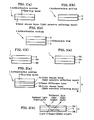
- Figs. 1 and 2 are each illustrative of the multilayer structure of a non-claimed authentication medium.
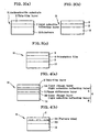
- Figs. 3 and 4 are illustrative of exemplary applications of a non-claimed authentication medium.
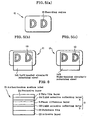
- Fig. 5 is illustrative of how authentication is implemented with a product with the non-claimed authentication medium applied to it.
- Fig. 6 is illustrative of a label form of a non-claimed authentication medium which is suitable for use on an application member.
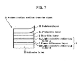
- Fig. 7 is illustrative of a transfer sheet form of a non-claimed authentication medium which is suitable for use on an application member.
- an authentication medium 1 comprises a multilayer structure in which a thin-film layer 2 that changes in light transmittance or reflectance upon heating is stacked on a color change layer 3 that changes in color depending of an angle of viewing, as depicted in Fig. 1(a) .
- the authentication medium 1 may have a multilayer structure with the color change layer 3 stacked on the thin-film layer 2, as depicted in Fig. 1(b) .
- the color change layer 3 may be formed of a variety of materials; for instance, it may be formed using a pigment that changes in color depending on the angle of viewing, a vapor deposited thin film or a dichromatic dye.
- a pigment that changes in color depending on the angle of viewing is a pearl pigment in which a layer formed of silicon oxide, titanium oxide, iron oxide or the like, each having a high refractive index and a layer formed of mica or the like having a low refractive index are stacked together.
- Infinite Color made by Shiseido Co., Ltd. and Iriodin made by Merck (Germany) are available.
- Vapor deposited thin films are formed of metals inclusive of aluminum or other materials by means of vapor phase processes.
- a very thin vapor deposited film is of transparency and gives out the so-called interference color changing dependent on the angle of viewing just as an oil thin film on the surface of water.
- a dichromatic dye comprises a long-chain dye molecule differing in light absorbance depending on a molecular axis and, for instance, has the nature that a light component in a normal direction to the molecular axis is substantially not absorbed or transmitted, whereas a light component in a direction parallel with the molecular axis is absorbed or not transmitted.
- Exemplary dichromatic dyes are anthraquinone, azo or bisazo-based dyes.
- each may be dispersed in a suitable binder resin and diluted with a solvent into a coating composition. Then, the coating composition may be applied to the surface of an application member by beans of silk screen printing, gravure printing or other known coating techniques.
- the color change layer 3 that forms a part of the authentication medium may be a light selective reflecting layer able to selectively reflect either left-handed or right-handed circularly polarized light of incident light.
- the authentication medium 1 may comprise a multilayer structure that has additionally an orientation film 4 between the color change layer 3 and the thin-film layer 2, as depicted in Fig. 1(c) .
- the authentication medium 1 may comprise a multilayer structure formed of, in order from below, the light selective reflecting layer 3, the orientation layer 4, and the thin-film layer 2.
- the authentication medium 1 may just as easily have the color change layer 3 formed of double layers.
- the authentication medium 1 may just as easily have the color change layer 3 formed of double layers.
- there may be a multilayer structure wherein, in order from below, two color change layers 3B and 3A and the thin-film layer 2 are stacked together as depicted in Fig. 1(d) or, alternatively, a multilayer structure wherein, in order from below, the thin-film layer 2 and two color change layers 3A and 3B are stacked together, as depicted in Fig. 1(e) .
- the authentication medium 1 may have a multilayer structure wherein, in order from below, the color change layer, for instance, the light selective reflecting layer 3B, a phase difference layer 5 and the color change layer, for instance, 3A, as depicted in Fig. 2(a) .
- the light selective reflecting layers 3B and 3A are preferably each formed of a cholesteric liquid crystal layer, and more preferably both adapted to reflect circularly polarized light in the same direction.
- the thin-film layer 2 is stacked on the side of the light selective reflecting layer A (3A) to form the authentication medium 1; of course, however, the thin-film layer 2 may just as easily stacked on the side of the light selective reflecting layer B (3B) to form the authentication medium 1.
- the phase difference layer 5 here is a layer that is adapted to double refract incident light to produce a phase differing depending on the direction of polarization, thereby making a phase difference.
- the phase difference p depends on the wavelength ⁇ of light.
- it makes a phase difference ⁇ ⁇ (that is, 1/2 wavelength) while that right-handed circularly polarized light is transmitted through.
- the incident right-handed circularly polarized light is converted into left-handed circularly polarized light before leaving the phase difference layer 5
- incident left-handed circularly polarized light is converted into right-handed circularly polarized light before leaving the phase difference layer 5.
- Such a phase difference layer 5 may be formed, using not only a stretched plastic film as a transparent substrate film but also a nematic liquid crystal layer optionally with a transparent substrate film, as will be described later.
- the color change layer 3 having a multilayer structure wherein the two color change layers B and A (3B and 3A) are stacked with the phase difference layer 5 interleaved between them is generally transparent at a time when the color change layers 3B and 3B are thin enough, so that an object on the opposite side can be seen through that multilayer structure.
- the two color change layers comprised light selective reflecting layers B and A (3B and 3A), each adapted to reflect right-handed circularly polarized light.
- the two color change layers comprised light selective reflecting layers B and A (3B and 3A), each adapted to reflect right-handed circularly polarized light.
- the natural light is now incident on the aforesaid basic elements from the side of the light selective reflecting layer A (3A) as depicted in Fig. 2(b) , it allows only right-handed circularly polarized light to be selectively reflected under the action of the light selective reflecting layer A (3A) because the natural light includes right-handed and left-handed circularly polarized light, so that the reflected light (right-handed circularly polarized light) can be observed by way of a right-handed circularly polarizing sheet.
- left-handed circular polarized light of the natural light incident from the light selective reflecting layer A (3A) transmits through the light selective reflecting layer A (3A).
- the transmitted left-handed circularly polarized light is converted into right-handed circularly polarized light through the phase difference layer 5 (in Fig. 2(b) , "left ⁇ right” is indicative of the conversion of left-handed into right-handed circularly polarized light).
- the converted right-handed circularly polarized light is reflected off the light selective reflecting layer B (3B). This reflected light (right-handed circularly polarized light) is converted into left-handed circularly polarized light after again passing through the phase difference layer 5 (in Fig.
- "right ⁇ left” is indicative of the conversion of right-handed into left-handed circularly polarized light).
- the converted left-handed circularly polarized light leaves the light selective reflecting layer A (3A), enabling the exit light (left-handed circularly polarized light) to be observed by way of a left-handed circularly polarizing sheet.
- the two light selective reflecting layers A and B (3A and 3b) are designed in such a way as to have reflected light having different center wavelengths, it is then possible to implement double check making authentication surer, because there is the color of light differing between on observation with the right-handed circularly polarizing sheet and on observation with the left-handed circularly polarizing sheet.
- the authentication medium 1 is preferably used as an authenticable substrate in the form of a multilayer assembly with a suitable substrate material.
- a color change layer for instance, a light selective reflecting layer 3 and a thin-film layer 2 are stacked on a suitable substrate 12 in order from the side of the substrate 12, another one wherein, as depicted in Fig. 3(b) , a thin-film layer 2 and a color change layer, for instance, a light selective reflecting layer 3 are stacked on a suitable substrate 12 in order from the side of the substrate 12, and yet another one wherein, as depicted in Fig.
- Each authenticable assembly 11 is a multilayer structure wherein the authentication medium 1 explained with reference to Fig. 1(a), 1(b), and 1(c) is stacked on the substrate 12.
- An authenticable assembly 11 depicted in Fig. 4(a) has a multilayer structure wherein the authentication medium 1 explained with reference to Fig. 2(a) is stacked on a suitable substrate 12, that is, a color change layer, for instance, a light selective reflecting layer 3 and a thin-film layer 2 are stacked on the substrate 12 in order from the side of the substrate 12.
- the light selective reflecting layer 3 comprises a multilayer structure wherein, in order from the side of the substrate 12, a light selective reflecting layer B (3B), a phase difference layer 5 and a light selective reflecting layer A (3A) are stacked together.
- a multilayer assembly wherein, in order from the side of the substrate 12, the thin-film layer 2, the light selective reflecting layer A (3A), the phase difference layer 5 and the light selective reflecting layer B (3B) are stacked together, too, provides the authenticable multilayer assembly 11.
- the authenticable multilayer assembly 11 may just as easily comprise a multilayer structure wherein a color change layer, for instance, a light selective reflecting layer B (3B), a pattern form of color change layer, for instance, a light selective reflecting layer A (3A) and a thin-film layer 2 are stacked on a substrate 12 in order from the side of the substrate 12; that is, the authentication medium 1 explained with reference to Fig. 1(d) is stacked on the substrate 12.
- the color change layer 3 comprises two or more layers, at least one layer may be in a pattern form.
- the authenticable assembly 11 may just as easily have a multilayer structure wherein the thin-film layer 2, the pattern form of color change layer, for instance, the light selective reflecting layer A (3A) and the light selective reflecting layer B (3B) are stacked together in order from the substrate 12. In any case, the order of stacking of the pattern form of light selective reflecting layer A (3A) and the light selective reflecting layer B (3B) may be reversed.
- the thin-film layer 2 in the authentication medium 1 should preferably change in light transmittance or reflectance upon heating.
- any desired material may be used provided that upon heating it undergoes melting, evaporation or a phase change to generate a pattern based on a light transmittance or reflectance difference between a portion heated and a portion unheated.
- a relatively low melting metal such as Te, Sn, In, Al, Bi, Pb, or Zn, or their alloy or their compound such as Te-carbide.
- the thin-film layer 2 may be formed by way of a vacuum vapor deposition technique, a sputtering technique or a plating technique, although depending on the material used.
- the thin-film layer 2 has a thickness of about 10 ⁇ m to 1,000 ⁇ m.
- the light selective reflecting layer 3 in the authentication medium 1 of the present invention is a layer formed of a light selective reflecting material able to selectively reflect either one of left-handed or right-handed circularly polarized light of incident light, for instance, a cholesteric crystal layer.
- the light selective reflecting layer 3 may be formed by the application and drying of a solution of cholesteric liquid crystals in a solvent by means of various printing techniques. Alternatively, it may be formed by preparing an ultraviolet polymerizable composition using polymerizable cholesteric liquid crystals, applying and drying the obtained ultraviolet polymerizable composition by means of various printing techniques, and thereafter irradiating that composition with ultraviolet radiation for polymerization.
- the center wavelength of reflected light differs for each layer.
- those layers are formed with different thicknesses, or they are formed using materials having different helical pitches.
- the light selective reflecting layer is formed of an ultraviolet polymerizable composition prepared using polymerizable chloresteric liquid crystals as mentioned above, polymerizable nematic liquid crystals are used in combination with a chiral agent. And then, if an ultraviolet polymerizable composition prepared using the polymerizable nematic liquid crystals and the chiral agent at varying blend ratios is used, it is then possible to form cholesteric liquid crystal layers having different helical pitches.
- the polymerizable cholesteric liquid crystal materials used here are represented by compounds having the following general formula (1), and compounds having formulae (2) to (10). These compounds are monomers, but they may be in oligomer or polymer forms.
- the compounds having general formula (1) may be used in combination of two or more, and the compounds having general formula (1) and the compounds having formulae (1) to (10) may be used in combination of two or more as well.
- R 1 and R 2 are each hydrogen or a methyl group
- X is chlorine or a methyl group
- Small letters a and b indicative of the chain length of an alkylene group that is a spacer in the compounds having general formula (1) are preferably in the range of 2 to 9 so as to bring liquid crystals to an active level.
- the aforesaid liquid crystal compound may contain a chiral agent as represented by formulae (11) to (13) given just below.
- R 3 is indicative of hydrogen or a methyl group.
- Y is any one of formulas (i) to (xxiv) given by formulae (14) and (15) given below.
- small letters c , d and e indicative of the chain length of an alkylene group is preferably in the range of 2 to 9 so as to bring liquid crystals to an active level.
- an ultraviolet polymerization initiator together with a solvent and a diluent may be mixed with the cholesteric liquid crystal material and the chiral agent, for instance, at a cholesteric liquid crystal material:chiral agent:ultraviolet polymerization initiator blend ratio of 100:5:5 by mass.
- the obtained powders may then be dissolved in a solvent such as toluene to prepare a coating solution having a concentration of about 30% by mass.
- blend ratios may be determined optionally depending on the cholesteric liquid crystal material and chiral agent used, the type of the ultraviolet polymerization initiator or the like, the coating mode and machine, and/or the desired coating amount.
- the orientation film 4, on which the light selective reflecting layer 3 can be stacked may be formed of any desired material such as polyvinyl alcohol resins (PVA) and polyimide resins provided that it can be used as a general orientation film.
- PVA polyvinyl alcohol resins
- the orientation film 4 is formed by coating a solution of these resins in a solvent on a film or other suitable layer by means of a suitable coating technique, followed by drying, and rubbing with cloth, a brush or the like. It is here noted that when the film or the like is formed of a stretched plastic sheet, the orientation film 4 may be omitted, because the surface of that film has orientation capability as its own surface property.
- the phase difference layer 5 may be formed using nematic liquid crystals. Specifically, it may be formed of an ink composition containing nematic liquid crystals, preferably, an ink composition comprising a solution of nematic liquid crystals in a solvent by means of various printing techniques.
- the phase difference layer 5 may be used just only alone, but also it may be stacked on the surface of a transparent film having orientation capability in itself optionally through the orientation film.
- phase difference layer 5 a stretched plastic film itself, too, can become the phase difference layer 5, and that a multilayer assembly wherein a phase difference layer is stacked on such a plastic film, a multilayer assembly wherein a phase difference layer is stacked on a plastic film through an orientation film 6 or the like may also generally function as the phase difference layer 5.
- a substrate 12, on which the authentication medium 1 is to be stacked may be formed of paper, plastics, metal foils or their composite materials. More practically, the substrate 12 may have been processed in the form of so-called cards such as credit cards and bank cards, various tradable coupons, commuting passes or ID cards which, if counterfeited or doctored, may incur various hassles.
- the aforesaid material has often been printed, laminated, embossed or otherwise processed, or provided thereon with a magnetic recording layer or embedded therein with an IC chip. In most cases, the substrate 12 has been printed, or provided thereon with a magnetic recording layer.
- Fig. 5(a) is illustrative of an authentication medium 1 stacked all over the surface of a substrate, wherein there is a recording area 13 provided on an authenticable assembly 11. In the example shown, capitals "DD" are formed on the recording area 13.
- the authenticable assembly 11 has been described with reference to Fig. 3 or Fig. 4 .
- the authentication medium 1 may be used with non-heat sensitive recording techniques using an ink jet printer, a thermal transfer printer, etc. Recordings applied by such non-heat-sensitive recording techniques get to have counterfeit-proof capability against the backdrop of the thin-film layer that changes in light transmittance or reflectance upon heating and/or the color change layer that change in color depending on the angle of viewing. If the aforesaid non-heat sensitive recording techniques are used in combination with the thermal recording techniques using a thermal head, laser light or the like, much higher counterfeit-proof capability can then be added to the authentication medium 1.
- a left-handed circularly polarizing sheet 14L is put over the authenticable assembly 11 in the state of Fig. 5(a) , as depicted in Fig. 5(b) .
- the light selective reflecting layer 3 is adaptive to selectively reflect the left-handed circularly polarized light of incident light, the reflected light will be observed, or seen colored on the basis of the thickness or helical pitch of the light selective reflecting layer 3.
- a right-handed circularly polarizing sheet 14R is put over as depicted in Fig. 5(c) , on the contrary, there will be no reflected light observed.
- the authenticable assembly 11 depicted in Fig. 5(a) is the one described with reference to Fig. 4(a) and the light selective reflecting layers A (3A) and B (3B) are adaptive to selectively reflect right-handed circularly polarized light.
- the left-handed circularly polarizing sheet 14L is put over as depicted in Fig. 5(b)
- the light reflected off the light selective reflecting layer B (3B) located below will be seen
- the right-handed circularly polarizing sheet 14R is put over as depicted in Fig. 5(c)
- the light reflected off the light selective reflecting layer A (3A) located above will be seen.
- the reflected light will be seen colored on the basis of the thickness or helical pitch of the light selective reflecting layer A (3A) or B (3B).
- the color of light there is then a difference in the color of light between on observation with the left-handed circularly polarizing sheet 14L and on observation with right-handed circularly polarizing sheet 14R, which makes double check achievable and authentication surer as well.
- the authentication medium 1 While reference has been made to the case where the authentication medium 1 is stacked on the surface of the substrate 12, especially on its viewing side, it should be understood that if the substrate 12 is transparent, the authentication medium 1 may then be stacked on its non-viewing side. Further, if the authentication medium 1 is cut into a very narrow, elongate thread form of about 0.5 mm to about 5 mm, then it may be put on a recess in the substrate 12 or visibly embedded in a substrate such as paper. If a thread form of authentication medium 1 is applied onto the substrate, e.g., a tradable coupon paper, then it remains unnoticeable or looks just as a simple decoration, but it makes sure the authentication of that paper, as mentioned above.
- a thread form of authentication medium 1 is applied onto the substrate, e.g., a tradable coupon paper, then it remains unnoticeable or looks just as a simple decoration, but it makes sure the authentication of that paper, as mentioned above.
- the authentication medium 1 described with reference to Figs. 1 and 2 is configured or otherwise processed into label, transfer sheet or other forms, as explained with reference to Fig. 6 or 7 , then it can be more easily applied to various articles or objects.
- Fig. 6 is illustrative of a label form of authentication medium.
- a color change layer for instance, a light selective reflecting layer B (3B), a phase difference layer 5, a color change layer, for instance, a light selective reflecting layer A (3A), a thin-film layer 2 and a protective layer 24 are stacked in order from the side of the substrate film 22, and on the lower surface side of the substrate film 22, an adhesive layer 23 is stacked, thereby forming an authentication medium label 21.
- a releasable sheet is provided on an exposed surface of the adhesive layer 23.
- the protective layer 24 is provided as the uppermost layer, and the adhesive layer 23 is stacked on the lower surface side of the substrate 22.
- the authentication medium 1 may contain more than does the one described with reference to Fig. 2(a) . It is also possible to make do without the protective layer 24.
- the authentication medium 1 plus the adhesive layer 23 may just as easily be stacked on the lower surface side of the substrate film 22, or when the authentication medium 1 plus the adhesive layer 23 are stacked on the lower surface side of the substrate film 22 as mentioned above, the protective layer 24 may be stacked on the upper surface side of the substrate film 22.
- Fig. 7 is illustrative of a transfer sheet form.
- a transfer sheet form In the example of an authentication medium transfer sheet 31 shown, on the lower surface side of a substrate film 22, a protective layer 24, a thin-film layer 2, a color change layer, for instance, a light selective reflecting layer 3 and an adhesive layer 23 are stacked in this order, with the substrate film 22 releasable from the protective layer 24.
- the light selective reflecting layer 3 has a multilayer structure wherein a light selective reflecting layer A (3A), a phase difference layer 5 and a light selective reflecting layer B (3B) are stacked in order from the thin-film layer 2 side.
- the authentication medium 1 described with reference to Fig. 2(a) is stacked.
- the authentication medium 1 may contain more than does the one described with reference to Fig. 2(a) . It is also possible to make do without the protective layer 24. Further, it is noted that when an adhesive is applied onto the surface of an application member, it is also possible to make do without the adhesive layer 23 provided as the lowermost layer.
- the authenticable assembly 11 may just as easily be used in place of various multilayer structures of the authentication medium 1.
- the authentication medium label 21, and the authentication medium transfer sheet 31 comes to have both the substrate film 22 and the substrate 12, because the authenticable assembly 11 involves the substrate 12 in itself.
- the authentication medium 1 or the authenticable assembly 11 may be fabricated by the successive stacking of the respective layers on a suitable permanent or temporary substrate or, alternatively, it may be fabricated by use of the authentication medium label 21 or the authentication medium transfer sheet 31 configured as described above. After peeling off the releasable sheet if any, the authentication medium label 21 may be applied at the adhesive layer 23 to an article that is an application member, and the authentication medium transfer sheet 31 may be bonded at the adhesive layer 23 to an article that is an application member, followed by a release of the substrate film 22.
- the substrate film 22 for the formation of the authentication medium label 21, and the authentication medium transfer sheet 31 should preferably have mechanical strength as well as solvent and heat resistance well capable of standing up to a processing operation for the fabrication of the label 21, and the transfer sheet 31.
- plastic films such as those based on polyethylene terephthalate (PET), polycarbonate, polyvinyl alcohol, polysulfone, polyethylene, polypropylene, polystyrene, polyarylate, triacetyl cellulose (TAC), diacetyl cellulose, and polyethylene/vinyl alcohol.
- the adhesive layer 23 that forms a part of the authentication medium label 21, and the authentication medium transfer sheet 31 either heat-sensitive adhesives or pressure-sensitive adhesives may be used.
- thermoplastic resins or thermal setting resins used as a binder resin in general ink or coating materials used, but also ionizing radiation curable resins such as ultraviolet or electron beam curable resins are usable.
- a polymerizable cholesteric liquid crystal solution was gravure printed on the surface of a 50 ⁇ m thick PET film, then dried, and finally irradiated with ultraviolet radiation to form a 2.2 ⁇ m thick cholesteric liquid crystal layer all over the surface.
- the polymerizable cholesteric liquid crystal solution used here was a 20% solution containing a polymerizable nematic liquid crystal ("Palio Color LC242" made by BASF), a chiral agent (“Palio Color LC756" made by BASF) and an ultraviolet polymerization initiator with toluene as a solvent.
- the polymerizable nematic liquid crystal/chiral agent blend ratio was 95.5/4.5, and the content of the ultraviolet polymerization initiator was 5% relative to the polymerizable nematic liquid crystal.
- a polyester resin base anchor coating layer was gravure printed on the thus formed cholesteric liquid crystal layer, a 250 nm thick Sn thin-film layer was formed on the anchor coating layer by means of vapor deposition, and a urethane resin base protective layer was gravure printed on the Sn thin-film layer to obtain a thermal recording film.
- thermal head printing was carried out from the protective layer side of the thermal recording film.
- the hue of the cholesteric liquid crystal layer at the printed site changed depending on the angle of viewing.
- the printed site was viewed through a right-handed circularly polarizing sheet put over it, it was seen in green, and upon changing to a left-handed circularly polarizing sheet, that color was out of sight.
- a release paper with an adhesive coated on it was put over the surface, with nothing applied on it, of the PET film of the thermal recording film obtained in Example 1 to obtain a multilayer structure in which the protective layer, Sn thin-film layer, anchor coating layer, cholesteric liquid crystal layer, PET film, adhesive layer and release paper were stacked together in this order. Then, that multilayer structure was punched out in a given shape to obtain a label form of thermal recording film.
- a multilayer structure with a heat-sensitive adhesive layer applied on each surface of the thermal recording film obtained in Example 1 was processed into a 2 mm wide thread form interleaved between paper layers to obtain a thread paper sheet.
- a 250 nm thick Sn thin-film layer was formed by vapor deposition on the surface of a 12 ⁇ m thick PET film.
- a PVA solution (a 5% aqueous solution (transparent) of PVA Resin made by Kuraray Co., Ltd.: Product No. 110) was coated and dried on the Sn thin-film layer, and then rubbed to form an orientation film.
- the same polymerizable cholesteric liquid crystal layer as used in Example 1 was gravure printed on that orientation film, then dried, and finally irradiated with ultraviolet radiation to obtain a thermal recording film with a 2.2 ⁇ m thick cholesteric liquid crystal layer formed all over the surface.
- thermal head printing was carried out from the PET film side of the thermal recording film.
- the hue of the cholesteric liquid crystal layer at the printed site changed depending on the angle of viewing.
- the printed site was viewed through a right-handed circularly polarizing sheet put over it, it was seen in green, and upon changing to a left-handed circularly polarizing sheet, that color was out of sight.
- Example 2 The same polymerizable cholesteric liquid crystal solution as used in Example 1 was gravure printed on one surface of a 50 ⁇ m thick PET film, then dried, and finally irradiated with ultraviolet radiation to form a 2.2 ⁇ m thick cholesteric liquid crystal layer (A) all over that surface. Subsequently, a polymerizable cholesteric liquid crystal solution different from that for the cholesteric liquid crystal layer (A) was formed on the surface of the PET film that faced away from the cholesteric liquid crystal layer (A) to form a cholesteric liquid crystal layer (B). Thereafter, a 250 nm thick Sn thin-film layer was formed by vapor deposition on the cholesteric liquid crystal layer (B) to obtain a thermal recording film.
- the polymerizable cholesteric liquid crystal layer used to form the cholesteric liquid crystal layer (B) was similar to that used for the cholesteric liquid crystal layer (A) with the exception that the polymerizable nematic liquid crystal/chiral agent blend ratio was 95.5/4.5.
- thermal head printing was carried out on the thermal recording film.
- the hue of each cholesteric liquid crystal layer at the printed site changed depending on the angle of viewing.
- the printed site was viewed through a right-handed circularly polarizing sheet put over it, it was seen in green, and upon changing to a left-handed circularly polarizing sheet, that color turned into red.
- Fig. 8 is illustrative of the basic multilayer structure of another non-claimed authentication medium useful for understanding the present invention.
- Figs. 9 and 10 are illustrative of a preferable embodiment of an authentication medium according to the present invention.
- Fig. 11 is illustrative of a form suitable for the application to an article of another authentication medium according to the present invention.
- Fig. 12 is illustrative of an example of application of another authentication medium of the present invention.
- another authentication medium 41 has a multilayer structure comprising two light selective reflecting layers A and B (43A and 43B) between which there is a phase difference layer 42 interleaved, as depicted in Fig. 8(a) .
- Two light selective reflecting layers A and B (43A and 43B) are each preferably formed of a material having light selective reflecting capability enough to selectively reflect either one of left-handed or right-handed circularly polarized light of incident light, and most preferably both are adaptive to reflect the circularly polarized light in the same direction.
- those layers A and B may be each formed of a cholesteric liquid crystal layer. It is also preferable that two such light selective reflecting layers A and B (43A and 43B) have a different center wavelength of reflected light.
- the phase difference layer 42 interleaved between the two light selective reflecting layers A and B is a layer that is adapted to double refract incident light to produce a phase differing depending on the direction of polarization, thereby making a phase difference.
- the phase difference p depends on the wavelength ⁇ of light.
- the incident right-handed circularly polarized light is converted into left-handed circularly polarized light before leaving the phase difference layer 5
- incident left-handed circularly polarized light is converted into right-handed circularly polarized light before leaving the phase difference layer 5.
- Such a phase difference layer 42 may be formed, using not only a stretched plastic film as a transparent substrate film but also a nematic liquid crystal layer optionally with a transparent substrate film, as will be describe later.
- the aforesaid basic arrangement i.e., the multilayer assembly having a multilayer structure wherein the two light selective reflecting layers A and B (43A and 43B) are stacked with the phase difference layer 42 interleaved between them is generally transparent at a time when the respective light selective reflecting layers A and B are thin enough, so that an object on the opposite side can be seen through that multilayer assembly.
- the multilayer structure of that basic arrangement there are some variations, as will be described later.
- the two light selective reflecting layers A and B were each adapted to selectively reflect right-handed circularly polarized light.
- natural light is now incident on the aforesaid basic elements from the side of the light selective reflecting layer A (43A) as depicted in Fig. 8(b) , it allows only right-handed circularly polarized light to be selectively reflected under the action of the light selective reflecting layer A (43A) because the natural light includes right-handed and left-handed circularly polarized light, so that the reflected light (right-handed circularly polarized light) can be observed by way of a right-handed circularly polarizing sheet.
- left-handed circular polarized light of the natural light incident from the light selective reflecting layer A (43A) side transmits through the light selective reflecting layer A (43A).
- the transmitted left-handed circularly polarized light is converted into right-handed circularly polarized light through the phase difference layer 42 (in Fig. 8(b) , "left ⁇ right” is indicative of the conversion of left-handed into right-handed circularly polarized light).
- the converted right-handed circularly polarized light is reflected off the light selective reflecting layer B (43B). This reflected light (right-handed circularly polarized light) is converted into left-handed circularly polarized light after again passing through the phase difference layer 42 (in Fig.
- the authentication medium 41 basically constructed as described with reference to Fig. 8 is affixed or otherwise applied to an article for which authentication is required, then the lower layer can be seen through.
- the sole use of the right-handed or left-handed circularly polarizing sheet allows the light taking such different paths as mentioned above to be observed.
- the two light selective reflecting layers A and B (43A and 43b) designed in such a way as to have reflected light having different center wavelengths it is then possible to implement double check making authentication surer, because there is a difference in the color of light between on observation with the right-handed circularly polarizing sheet and on observation with the left-handed circularly polarizing sheet.
- the authentication medium 41 may be applied to various articles alone or in combination with other authenticable means.
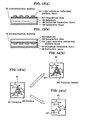
- Fig. 9 is illustrative of an example of application of the basic elements explained with reference to Fig. 8 to a hologram.
- a light selective reflecting layer A (43A) is stacked on one surface of a transparent substrate film 421, and a light selective reflecting layer B (43B), a hologram-formation layer 4 and a reflective layer 5 are stacked in this order on the side of the transparent substrate film 421 that faces away from the light selective reflecting layer A (43A), as depicted in Fig. 9(a) .
- the authentication medium 41 of the present invention may just as easily have a multilayer structure wherein a phase difference layer 42 and a light selective reflecting layer A (43A) are stacked in this order on one surface of a transparent substrate film 421, and a light selective reflecting layer B (43B), a hologram-formation layer 44 and a reflective layer 45 are stacked in this order on the side of the transparent substrate film 421 that faces away from the phase difference layer 42 and light selective reflecting layer A (43A).
- the transparent substrate film 421 has both a support function and a function as the phase difference layer 42.
- the multilayer here wherein there are the light selective reflecting layer A (43A), phase difference layer 42, transparent substrate film 421 and light selective reflecting layer B (43B) stacked in this order, too, is one variation of the basic multilayer structure of the authentication medium 41 of the present invention.
- the authentication medium 41 of the present invention may just as easily have a multilayer structure wherein a transparent substrate 421 and a phase difference layer 42 are stacked with an orientation film A (46A) interleaved between them, and the transparent substrate film 421 and a light selective reflecting layer B (43B) are stacked with an orientation film B (46B) interleaved between them.
- the multilayer structure here wherein there are a light selective reflecting layer A (43A), the phase difference layer 42, the orientation layer A (46A), the transparent substrate film 421, the orientation film B (46B) and a light selective reflecting layer B (43B) stacked in this order, too, is one variation of the basic multilayer structure of the authentication medium 41 of the present invention.
- the hologram-formation layer and reflective layer on the back surface side ensure the visibility of the hologram, because the already explained basic elements can be seen through. Further, when both light selective reflecting layers A and B (43A and 43B) are able to selectively reflect either one of left-handed or right-handed circularly polarized light of incident light and there is a difference in the center wavelength of reflected light, there is a different color observed upon viewing with a right-handed circularly polarizing sheet, and a left-handed circularly polarizing sheet.
- the authentication medium 41 when used for authentication purposes, not only does the appearance and characteristics of the hologram make sure difficulty of fabrication, but also authentication can be implemented with double check means relying on a right-handed and a left-handed circularly polarizing sheet, so that an article to which such an authentication medium is applied has an advantage of authentication being implemented with an ever higher reliability.
- the two light selective reflecting layers A and B (43A and 43B) in the authentication medium 41 are each a layer formed of a light selective reflecting material able to selectively reflect either one of left-handed and right-handed circularly polarized light of incident light, for instance, a cholesteric crystal layer.
- the two light selective reflecting layers A and B may be formed by the application and drying of a solution of cholesteric liquid crystals in a solvent by means of various printing techniques.
- they may be formed by preparing an ultraviolet polymerizable composition using polymerizable cholesteric liquid crystals, applying and drying the obtained ultraviolet polymerizable composition by means of various printing techniques, and thereafter irradiating that composition with ultraviolet radiation for polymerization.
- the center wavelength of reflected light differs for each layer.
- those layers are formed with different thicknesses, or they are formed using materials having different helical pitches.
- the light selective reflecting layer is formed of an ultraviolet polymerizable composition prepared using polymerizable chloresteric liquid crystals as mentioned above, polymerizable nematic liquid crystals are used in combination with a chiral agent. And then, if an ultraviolet polymerizable composition prepared using the polymerizable nematic liquid crystals and the chiral agent at varying blend ratios is used, it is then possible to form cholesteric liquid crystal layers having different helical pitches.
- the transparent substrate film 421 it is preferable to use a material that can be made thin, and has mechanical strength as well as solvent and heat resistance well capable of standing up to a processing operation for the fabrication of the authentication medium.
- a film or sheet form of plastic material preference is given to a film or sheet form of plastic material. Specific mention is made of various plastic films such as those based on polyethylene terephthalate (PET), polycarbonate, polyvinyl alcohol, polysulfone, polyethylene, polypropylene, polystyrene, polyarylate, triacetyl cellulose (TAC), diacetyl cellulose, and polyethylene/vinyl alcohol.
- an orientation film is stacked on one or each of the transparent substrate film 421.
- the orientation film may be formed of any desired material such as polyvinyl alcohol resins (PVA) and polyimide resins provided that it can be used as a general orientation film.
- PVA polyvinyl alcohol resins
- the orientation film is formed by coating a solution of these resins in a solvent on the transparent substrate film 421 by means of a suitable coating technique, followed by drying and rubbing with cloth, a brush or the like. It is here noted that when the transparent substrate film 421 is formed of a stretched plastic sheet, the orientation film may be dispensed with, because the surface of that film has orientation capability as its own surface property.
- the phase difference layer 42 may be formed using nematic liquid crystals. Specifically, it may be formed of an ink composition containing nematic liquid crystals, preferably, an ink composition comprising a solution of nematic liquid crystals in a solvent by means of various printing techniques.
- the phase difference layer 42 may be used just only alone, but also it may be stacked on the surface of the transparent substrate film 421 having orientation capability in itself optionally through the orientation film 46.
- the transparent substrate film 421 is a stretched plastic film itself, it can become the phase difference layer 42 too, and that a multilayer assembly wherein the phase difference layer 42 is stacked on the transparent substrate film 421, a multilayer assembly wherein the phase difference layer 42 is stacked on the transparent substrate film 421 through the orientation film 46 or the like may also generally function as the phase difference layer 42.
- the hologram-formation layer 44 has a fine relief pattern of relief hologram formed on one surface of a layer comprised of a transparent resin material.
- thermoplastic resins include acrylic ester resins, acrylamide resins, nitrocellulose resins, polystyrene resins or the like; and the thermosetting resins include unsaturated polyester resins, acrylic urethane resins, epoxy-modified acrylic resins, epoxy-modified unsaturated polyester resins, alkyd resins, phenol resins or the like. Those thermoplastic resins and thermosetting resins may be used alone or in combination of two or mores.
- One or two or more of such resins may be crosslinked by way of various isocyanate resins, or may be blended with various curing catalysts such as metal soaps, for instance, cobalt or zinc naphthenate, or thermal or ultraviolet polymerization initiators such as peroxides represented by benzoyl peroxide and methyl ethyl ketone peroxide, benzophenone, acetophenone, anthraquinone, naphthoquinone, azobisisobutyronitrile or diphenyl sulfide.
- the ionizing radiation curable resins include epoxy acrylate, urethane acrylate, acrylic-modified polyester or the like. It is acceptable to introduce a crosslinked structure in those ionizing radiation curable resins or blend with them mono- or poly-functional monomers, oligomers, etc. for the purpose of viscosity adjustment.
- the hologram-formation layer 44 may be formed directly from that resin material by subjecting a photosensitive resin material to holographic interference exposure, followed by development; however, it is preferable that a copying mold such as a previously formed relief hologram or its replica, or their plating mold is pressed at its surface against the aforesaid resin material for copying.
- a copying mold such as a previously formed relief hologram or its replica, or their plating mold is pressed at its surface against the aforesaid resin material for copying.
- the hologram-formation layer 44 here is understood to include a diffraction grating-formation layer having a pattern form of diffraction grating prepared in similar ways.
- the hologram-formation layer and the diffraction grating-formation layer will hereinafter be collectively called the light diffraction structure layer.
- the reflective layer 45 formed along the fine relief pattern of the relief hologram may be either a reflective metal thin film or a transparent layer having a refractive index different from that of the hologram-formation layer 44.
- the use of the former gives an opaque hologram, whereas the use of the latter gives a transparent hologram. In either case, there is a reflection hologram obtained, which is improved in visibility as viewed under illumination from the viewer side.
- the material for the formation of the reflective metal thin film includes metals such as Al, Cr, Ti, Fe, Co, Ni, Cu, Ag, Au, Ge, Mg, Sb, Pb, Cd, Bi, Sn, Se, In, Ga, and Rb, or their oxides or nitrides.
- the reflective metal thin film may also be formed of one or two or more of such materials. Among others, particular preference is given to Al, Cr, Ni, Ag, and Au, with a film thickness of preferably 1 nm to 10,000 nm, and more preferably 2 nm to 200 nm.
- the material for constituting the transparent layer having a refractive index different from that of the hologram-formation layer 44 there is a transparent material having a refractive index different from that of the resin material for the hologram-formation layer.
- the refractive index of that transparent material may be either larger or smaller than that of the resin of the hologram-formation layer; however, it is desired that there be a refractive index difference of preferably at least 0.1, more preferably at least 0.5, and even more preferably at least 1.0.
- titanium oxide (TiO 2 ) zinc sulfide (ZnS), a Cu ⁇ Al composite metal oxide and so on are preferred.
- a metal thin film of less than 20 nm in thickness may be used as the material for constituting the transparent layer having a refractive index different from that of the hologram-formation layer 44, because of having transparency.
- the reflective layer 45 may be provided by means of known techniques such as sublimation, vacuum vapor deposition, sputtering, reactive sputtering, ion plating, and electroplating.
- the authentication medium 41 described with reference to Figs. 8-10 is configured or otherwise processed into a label or transfer sheet form as explained with reference to Fig. 11 , whereby it may just as easily be applied to various articles.
- the authentication medium 41 ( Fig. 9(b) ) comprises a multilayer structure wherein a phase difference layer 42 and a light selective reflecting layer A (43A) are stacked in this order on one surface of a transparent substrate film 421, and a light selective reflecting layer B (43B), a hologram-formation layer 44 and a reflective layer 45 are stacked on the side of the transparent substrate film 421 that faces away from the phase difference layer 42 and light selective reflecting layer A (43A). Then, an adhesive layer 52 is stacked on the reflective layer 45 side of the authentication medium 41, thereby forming an authentication medium label 51.
- the authentication medium 41 that forms a part of the authentication medium label 42 not only the aforesaid multilayer structure but also other multilayer structures described with reference to Figs. 8-10 may be used.
- the authentication medium 41 ( Fig. 9(b) ) comprises a multilayer structure wherein a phase difference layer 42 and a light selective reflecting layer A (43A) are stacked on one surface of a transparent substrate film 421 and a light selective reflecting layer B (43B), a hologram-formation layer 44 and a reflective layer 45 are stacked on the side of the transparent substrate film 421 that faces away from the phase difference layer 42 and light selective reflecting layer A (43A).
- an adhesive layer 52 is stacked on the reflective layer 45 side of that medium 41 and the releasing surface 54a side of a releasable substrate 54 is stacked on the light selective reflecting A (43A) side of that medium 41, thereby forming an authentication medium transfer sheet 53.
- the authentication medium 41 that forms a part of the authentication medium transfer sheet 53 not only the aforesaid multilayer structure but also other multilayer structures described with reference to Figs. 8-10 may be used.
- a dark color layer such as a resin layer colored in black or like color is provided below each layer.
- a dark color layer may be interleaved between the reflective layer 45 and the adhesive layer 52 or, alternatively, a dark color adhesive layer colored in black or like color may be used to provide the adhesive layer 52 instead of using another dark color layer.
- the authentication medium 41 preferably in the form of the authentication medium label 51 or the authentication medium transfer sheet 53 as mentioned above, may be applied to various articles.
- the authentication medium label 51 may be applied at the adhesive layer 52 to an article that is an application side
- the authentication medium transfer sheet 53 may be applied at the adhesive layer 52 to an article that is an application member after the releasable substrate 54 is released off.
- Fig. 12 is illustrative of one exemplary application of the authentication medium 41 to be used primarily with a sheet form of article.
- What is illustrated in Fig. 12(a) is an authenticable information-recording medium 55 wherein the authentication medium 41 is stacked on a part of the surface of an information-recording medium 56.
- the information-recording medium 56 is configured in a sheet form that is made up of a paper, plastic sheet or other substrate.
- the information-recording medium 56 has information 57 recorded on it as by printing, said information including an amount of money available as a tradable coupon, the name of an issuer, instructions, patterns, etc.
- Fig. 12(b) What is depicted in Fig. 12(b) is an authentication medium 41 previously incorporated in a sheet form of article in a visible way.
- the sheet-like article made up of paper, a plastic sheet or the like is provided with a recess 59 that is not in a through-hole form, and through which the authentication medium 41 is seen.
- the authentication medium 41 is chopped into an elongate thread form having a very narrow width of about 0.5 mm to about 5 mm for the purpose of facilitating its application.
- the recess 59 is provided in the surface layer of some layers constituting paper, and the thread-like authentication medium 41 is interleaved or otherwise inserted between the remaining paper layers.
- one surface of the substrate, etc. is colored in a dark or like color, and to make sure adhesion between the thread-like authentication medium 41 and the sheet-like article in a state of the former being incorporated in the latter, it is preferable that an adhesive layer, preferably a heat-sensitive adhesive layer is stacked on one or each surface of the substrate.
- an adhesive layer preferably a heat-sensitive adhesive layer is stacked on one or each surface of the substrate.
- a polymerizable cholesteric liquid crystal solution (A) was gravure printed on the surface of a 50 ⁇ m thick PET film, then dried, and finally irradiated with ultraviolet radiation to form a 2.2 ⁇ m thick cholesteric liquid crystal layer (A) all over the surface.
- Another polymerizable cholesteric liquid crystal solution (B) was gravure printed on the surface of the PET film that faced away from the cholesteric liquid crystal layer (A), then dried, and finally irradiated with ultraviolet radiation to form a 2.2 ⁇ m thick cholesteric liquid crystal layer (B) all over the surface.
- the polymerizable cholesteric liquid crystal solution (A) used here was a 20% solution containing a polymerizable nematic liquid crystal ("Palio Color LC242" made by BASF), a chiral agent ("Palio Color LC756” made by BASF) and an ultraviolet polymerization initiator with toluene as a solvent.
- the polymerizable nematic liquid crystal/chiral agent blend ratio was 95.3/4.7, and the content of the ultraviolet polymerization initiator was 5% relative to the polymerizable nematic liquid crystal.
- the polymerizable cholesteric liquid crystal solution (B) was the same as the polymerizable cholesteric liquid crystal solution (A) with the exception that the polymerizable nematic liquid crystal/chiral agent blend ratio was 96.2/3.8.
- a transparent ultraviolet curable resin composition was coated on the cholesteric liquid crystal layer (B) side of the obtained composite film having a multilayer structure of cholesteric liquid crystal layer (A)/PET film/cholesteric liquid crystal layer (B), and brought into contact with the surface of a relief hologram-copying mold.
- the assembly was irradiated with ultraviolet radiation to cure the transparent ultraviolet curable resin composition to form a relief hologram.
- TiO 2 was vacuum vapor deposited on the surface with the relief hologram given to it to form a transparent reflective layer of 500 nm in thickness, thereby obtaining an authentication medium.
- the obtained authentication medium was viewed from the cholesteric liquid crystal layer (A) side at varying angles, it was found that there was a change in the color resulting from the cholesteric liquid crystal layer.
- a right-handed circularly polarizing sheet was put over the cholesteric liquid crystal layer (A) side of the authentication medium, the whole was seen in green, and upon changing from the right-handed to a left-handed circularly polarizing sheet, the whole was seen in red, indicating that authentication was well achievable.
- a polymerizable nematic liquid crystal solution was gravure coated on the surface of a 38 ⁇ m thick PET film, then dried, and finally irradiated with ultraviolet radiation to form a 1.0 ⁇ m thick nematic liquid crystal layer.
- the polymerizable nematic liquid crystal solution used here was a 15% solution containing a polymerizable nematic liquid crystal ("Palio Color LC242" made by BASF) and an ultraviolet polymerization initiator with toluene and cyclohexanone as solvents. The content of the ultraviolet polymerization initiator was 5% relative to the polymerizable nematic liquid crystal.
- Example 7 was repeated with the exception that the thus obtained nematic liquid crystal layer/PET film multilayer structure was used in place of the PET film in Example 7, thereby obtaining an authentication medium.
- the obtained authentication medium was viewed from the cholesteric liquid crystal layer (A) side at varying angles, it was found that there was a change in the color resulting from the cholesteric liquid crystal layer.
- a right-handed circularly polarizing sheet was put over the cholesteric liquid crystal layer (A) side of the authentication medium, the whole was seen in green, and upon changing from the right-handed to a left-handed circularly polarizing sheet, the whole was seen in red, indicating that authentication was well achievable.
- a PVA solution (a 5% aqueous solution (transparent) of PVA Resin made by Kuraray Co., Ltd.: Product No. 110) was coated and dried on the surface of a 75 ⁇ m thick TAC film, and then rubbed to form an orientation film.
- a 1.5 ⁇ m thick nematic liquid crystal layer was formed on the orientation film as in Example 8, and a 2.2 ⁇ m thick cholesteric liquid crystal layer (A) was formed all over the surface of the nematic liquid crystal layer as in Example 7.
- Example 7 a relief hologram and a 500 nm thick transparent reflective layer were formed in this order on an exposed surface side of the TAC film in the thus obtained composite film having a multilayer structure of cholesteric liquid crystal layer (A)/orientation film/TAC film, thereby obtaining an authentication medium with a relief hologram and a 500 nm thick transparent reflective layer formed in this order.
- the obtained authentication medium was viewed from the cholesteric liquid crystal layer (A) side at varying angles, it was found that there was a change in the color resulting from the cholesteric liquid crystal layer.
- a right-handed circularly polarizing sheet was put over the cholesteric liquid crystal layer (A) side of the authentication medium, the whole was seen in green, and upon changing from the right-handed to a left-handed circularly polarizing sheet, the whole was seen in red, indicating that authentication was well achievable.
- Yet another non-claimed authentication medium 61 comprises a multilayer structure wherein, as depicted in Fig. 13(a) , an orientation film 63 and a light selective reflecting pattern layer 64 are stacked in this order on the upper surface of a substrate 62 and a hologram-formation layer 65 as a light diffracting structure layer is stacked on the lower surface of the substrate 62, with a reflective layer (also called a light reflective layer) 66 stacked on the lower surface of the hologram-formation layer 65.
- the hologram-formation layer 66 has a fine relief hologram pattern along which the reflective layer 66 is stacked.
- the substrate 62 is located between the light selective reflecting pattern layer 64 and the hologram-formation layer 65 plus the reflective layer 66, so that the pattern layer 62 has no or little influence on the hologram-formation layer 65 and the reflective layer 66, and vice versa, at the time when they are formed.
- the authentication medium 61 may have a multilayer structure wherein on the lower surface of a substrate 62, there may be an orientation film 63, a light selective reflecting pattern layer 64, a hologram-formation layer 65 and a reflective layer 66 stacked in this order.
- the hologram-formation layer 65 has a fine relief hologram pattern on its lower surface side, along which the reflective layer 66 is formed. With the respective layers stacked on one side alone of the substrate, the substrate 62 with its upper surface remaining exposed may be used as a protective layer.
- each light selective reflecting pattern layer 64 is a layer made up of a material able to selectively reflect either one of left-handed or right-handed circularly polarized light of incident light, for instance, a cholesteric liquid crystal layer with a pattern formed depending on the presence or absence, or the thickness, of the layer.
- the reflective layer 66 for instance, is built up of a metal thin film or the like.
- each light selective reflecting pattern 64 may be constructed of two types of light selective reflecting pattern layers, an identical material having different thicknesses, or different materials. Further, one of the two types of light selective reflecting pattern layers may be in a uniform layer form.
- the orientation film 63 separate from the substrate 62 is needed; however, when a stretched plastic sheet is used as the substrate 62, it may be dispensed with because of its own orientation capability.
- the substrate 62 it is preferable to use a material that can be made thin, and has mechanical strength as well as solvent and heat resistance well capable of standing up to a processing operation for the fabrication of the authentication medium 61.
- a film or sheet form of plastic material preference is given to a film or sheet form of plastic material. Specific mention is made of various plastic films such as those based on polyethylene terephthalate (PET), polycarbonate, polyvinyl alcohol, polysulfone, polyethylene, polypropylene, polystyrene, polyarylate, triacetyl cellulose (TAC), diacetyl cellulose, and polyethylene/vinyl alcohol.
- the orientation film 63 may be formed of any desired material such as polyvinyl alcohol resins (PVA) and polyimide resins provided that it can be used as a general orientation film.
- the orientation film 63 is formed by coating a solution of these resins in a solvent on the surface of such a substrate 62 as mentioned above by means of a suitable coating technique, followed by drying, and rubbing with cloth, a brush or the like.
- PVA polyvinyl alcohol resins
- polyimide resins provided that it can be used as a general orientation film.
- the orientation film 63 is formed by coating a solution of these resins in a solvent on the surface of such a substrate 62 as mentioned above by means of a suitable coating technique, followed by drying, and rubbing with cloth, a brush or the like.
- an orientation film interleaved, if necessary, between the light selective reflecting pattern layers, too, may similarly be formed.
- the light selective reflecting pattern layer 64 is composed of a cholesteric liquid crystal layer.
- the cholesteric liquid crystal layer in an oriented state has the nature of reflecting only one of left-handed or right-handed circularly polarized light of incident light.
- the light selective reflecting pattern layer 64 may be formed by the application and drying in a pattern form of a solution of cholesteric liquid crystals in a solvent. Alternatively, it may be formed by the application and drying in a pattern form of an ultraviolet polymerizable composition comprising a polymerizable cholesteric liquid crystal, followed by irradiation with ultraviolet radiation for polymerization.
- the light selective reflecting pattern layer 64 is provided in a pattern form, it is preferable to make use of various printing techniques.
- two or more light selective reflecting pattern layers 64 are provided and at least one of them is formed as a uniform layer, it is preferable to make use of various coating techniques.
- the hologram-formation layer 65 has a fine relief pattern of relief hologram formed on one surface of a layer made up of a transparent resin material.
- thermoplastic resins include acrylic ester resins, acrylamide resins, nitrocellulose resins, polystyrene resins or the like; and the thermosetting resins include unsaturated polyester resins, acrylic urethane resins, epoxy-modified acrylic resins, epoxy-modified unsaturated polyester resins, alkyd resins, phenol resins or the like. Those thermoplastic resins and thermosetting resins may be used alone or in combination of two or mores.
- One or two or more of such resins may be crosslinked by way of various isocyanate resins, or may be blended with various curing catalysts such as metal soaps, for instance, cobalt or zinc naphthenate, or thermal or ultraviolet polymerization initiators such as peroxides represented by benzoyl peroxide and methyl ethyl ketone peroxide, benzophenone, acetophenone, anthraquinone, naphthoquinone, azobisisobutyronitrile or diphenyl sulfide.
- the ionizing radiation curable resins include epoxy acrylate, urethane acrylate, acrylic-modified polyester or the like. It is acceptable to introduce a crosslinked structure in those ionizing radiation curable resins or blend with them mono- or poly-functional monomers, oligomers, etc. for the purpose of viscosity adjustment.
- the hologram-formation layer 65 may be formed directly from that resin material by subjecting a photosensitive resin material to holographic interference exposure, followed by development; however, it is preferable that a copying mold such as a previously formed relief hologram or its replica, or their plating mold is pressed at its surface against the aforesaid resin material for copying.
- a copying mold such as a previously formed relief hologram or its replica, or their plating mold is pressed at its surface against the aforesaid resin material for copying.
- the reflective layer 66 formed along the fine relief pattern of relief hologram may be either a reflective metal thin film or a transparent layer having a refractive index different from that of the hologram-formation layer 65.
- the use of the former gives an opaque hologram, whereas the use of the latter gives a transparent hologram. In either case, there is a reflection hologram obtained, which is improved in visibility as viewed under illumination from the viewer side.
- the material for the formation of the reflective metal thin film includes metals such as Al, Cr, Ti, Fe, Co, Ni, Cu, Ag, Au, Ge, Mg, Sb, Pb, Cd, Bi, Sn, Se, In, Ga, and Rb, or their oxides or nitrides.
- the reflective metal thin film may also be formed of one or two or more of such materials. Among others, particular preference is given to Al, Cr, Ni, Ag, and Au, with a film thickness of preferably 1 nm to 10,000 nm, and more preferably 2 nm to 200 nm.
- the material for constituting the transparent layer having a refractive index different from that of the hologram-formation layer 65 there is a transparent material having a refractive index different from that of the resin material for the hologram-formation layer.
- the refractive index of that transparent material may be either larger or smaller than that of the resin of the hologram-formation layer; however, it is desired that there be a refractive index difference of preferably at least 0.1, more preferably at least 0.5, and even more preferably at least 1.0.
- titanium oxide (TiO 2 ) zinc sulfide (ZnS), a Cu ⁇ Al composite metal oxide and so on are preferred.
- a metal thin film of less than 20 nm in thickness may be used as the material for constituting the transparent layer having a refractive index different from that of the hologram-formation layer 65, because of having transparency.
- the reflective layer 66 may be provided by means of known techniques such as sublimation, vacuum vapor deposition, sputtering, reactive sputtering, ion plating, and electroplating.
- a hologram 67 recorded as a fine relief pattern on the lower surface of the hologram-formation layer 65 can be seen by way of the reflection of light off the reflective layer 66, as shown schematically in Fig. 14(a) .
- the light selective reflecting pattern layer 64 is transparent, but the authentication medium 61 is seen in different colors depending on the angle of viewing, say, it looks like a colored image 68' as depicted in Fig. 14(b) .
- the light selective reflecting pattern layer 64 is a layer made up of a material able to selectively reflect right-handed circularly polarized light. Then, as left-handed circularly polarized light enters the light selective reflecting pattern layer 64, left-handed circularly polarized light is not reflected, so the hologram 67 alone is seen without the image of a capital "A" being visualized, as depicted in Fig. 14(c) .
- authentication may be implemented as explained above.
- the authentication medium 61 having a multilayer structure comprising the light selective reflecting pattern 64 and the hologram-formation layer 65 differs in reflectance depending on the angle of viewing or by entering left-handed circularly polarized light in it, so that the viewer can see the authentication medium 61 in different ways. Therefore, by making sure how a genuine article is seen or entering left-handed circularly polarized light in both a genuine article and the article to be authenticated to compare them in terms of reflectance or what is seen, authentication may be implemented. It is here noted that to view the authentication medium with entrance of left-handed circularly polarized light in the light selective reflecting pattern layer 64, it is only needed to put a left-handed circularly polarizing sheet over the light selective reflecting pattern 64.
- the authentication medium 61 described with reference to Fig. 13 is configured or otherwise processed into a label or transfer sheet form, as will be explained with reference to Fig. 15 , then it can more easily be applied to various articles.
- Fig. 15(a) shows a label form.
- an authentication medium 71 is built up by stacking an adhesive layer 72 on the reflective layer 66 side of an authentication medium 61 having a multilayer structure wherein a substrate 62, a light selective reflecting pattern layer 64, a hologram-formation layer 65 and a reflective layer 66 are stacked together in this order.
- the authentication medium 61 for building up the authentication medium 71 not only the above multilayer structure but also each multilayer structure described with reference to Fig. 13 , with or without the orientation film 63, may be used.
- the stacking of the adhesive layer 72 on the reflective layer 66 side is more preferable for authentication purposes, as explained with reference to Fig. 15(a) ; however, it is sometime possible to stack the adhesive layer on the substrate 62 side.
- On which side of the authentication medium 61 the adhesive layer is to be stacked is determined depending on which of the reflective layer 66 side or the substrate 62 side defines an entrance surface when the label is applied to an article.
- the reflective layer 66 is made up of a reflective metal thin film (except a transparent one)
- the substrate 62 side defines the entrance surface.
- the authentication medium 61 is built up of a material that must have the orientation film 63, like a triacetyl cellulose film
- right-handed or left-handed circularly polarized light may be entered from either the reflective layer 66 side or the substrate 62 side.
- the authentication medium 62 is built up of a substrate that has its own surface orientation capability and so does not have to have any orientation film, like a polyethylene terephthalate or polycarbonate resin film, it is necessary to enter right-handed or left-handed circularly polarized light from the reflective layer 66 side.
- the adhesive layer 72 may be selected from various types of adhesive layers, but preference is given to a heat- or pressure-sensitive adhesive layer.
- Fig. 15(b) shows a transfer sheet form.
- an authentication medium transfer sheet 73 is built up by stacking an adhesive layer 72 on the reflective layer 66 side of an authentication medium 61 having a multilayer structure wherein a substrate 62, a light selective reflecting pattern layer 64, a hologram-formation layer 65 and a reflective layer 66 are stacked together in this order, and stacking the releasable surface 74a side of a releasable substrate 74 on the substrate 62 side.
- the authentication medium 61 for building up the authentication medium transfer sheet 73 just only the above multilayer structure but also each multilayer structure described with reference to Fig. 13 , with or without the orientation film 63, may be used.
- the adhesive layer 72 may be selected from various types of adhesive layers, but preference is given to a heat- or pressure-sensitive adhesive layer. Note here that the adhesive layer is applied to the surfaces of various articles to which the authentication medium 61 is to be applied, and there may be a transfer sheet built up with no adhesive layer.
- a dark color layer such as a resin layer colored in black or like color is provided below each layer.
- a dark color layer may be interleaved between the reflective layer 66 and the adhesive layer 72 or, alternatively, a dark color adhesive layer colored in black or like color may be used to provide the adhesive layer 72 instead of using another dark color layer.
- the authentication medium 61 preferably in the form of the authentication medium label 71 or the authentication medium transfer sheet 73 as mentioned above, may be applied to various articles.
- the authentication medium label 71 may be applied at the adhesive layer 72 to an article that is an application side, and the authentication medium transfer sheet 73 may be applied at the adhesive layer 72 to an article that is an application member after the releasable substrate 74 is released off.
- Fig. 16 is illustrative of one exemplary application of the authentication medium 61 to be used primarily with a sheet form of article.
- What is illustrated in Fig. 16(a) is an authenticable information-recording medium 75 wherein the authentication medium 61 is stacked on a part of the surface of an information-recording medium 76.
- the information-recording medium 76 is configured in a sheet form that is made up of a paper, plastic sheet or other substrate.
- the information-recording medium 76 has information 77 recorded on it as by printing, said information including an amount of money available as a tradable coupon, the name of an issuer, instructions, patterns, etc.
- FIG. 16(b) What is depicted in Fig. 16(b) is an authentication medium 61 previously incorporated in a sheet form of article in a visible way.
- the sheet-like article made up of paper, a plastic sheet or the like is provided with a recess 79 that is not in a through-hole form, and through which the authentication medium 61 is seen.
- the authentication medium 61 is chopped into an elongate thread form having a very narrow width of about 0.5 mm to about 5 mm for the purpose of facilitating its application.
- the recess 79 is provided in the surface layer of some layers constituting paper, and the thread-like authentication medium 61 is interleaved or otherwise inserted between the remaining paper layers.
- one surface of the substrate, etc. is colored in a dark or like color, and to make sure adhesion between the thread-like authentication medium 61 and the sheet-like article in a state of the former being incorporated in the latter, it is preferable that an adhesive layer, preferably a heat-sensitive adhesive layer is stacked on one or each surface of the substrate.
- an adhesive layer preferably a heat-sensitive adhesive layer is stacked on one or each surface of the substrate.
- a polymerizable cholesteric liquid crystal ink was gravure printed on the surface of a PET film, then dried, and finally irradiated with ultraviolet radiation to obtain a printed film with a character-and-pattern formed on it.
- the polymerizable cholesteric liquid crystal ink used here was a 40% solution containing a polymerizable nematic liquid crystal ("Palio Color LC242" made by BASF), a chiral agent (“Palio Color LC756" made by BASF) and an ultraviolet polymerization initiator with toluene as a solvent.
- the polymerizable nematic liquid crystal/chiral agent blend ratio was 95.5/4.5, and the content of the ultraviolet polymerization initiator was 5% relative to the polymerizable nematic liquid crystal.
- a transparent ultraviolet curable resin composition was coated on the unprinted surface of the printed film, and brought into contact with the surface of a relief hologram-copying mold. In that state, the assembly was irradiated with ultraviolet radiation to cure the transparent ultraviolet curable resin composition to form a relief hologram. Thereafter, ZnS was vacuum vapor deposited on the surface with the relief hologram given to it to form a transparent reflective layer of 400 nm in thickness, thereby obtaining an authentication medium.
- the obtained authentication medium was viewed from the reflective layer side, the hologram, and the printed character-and-pattern was seen, and the printed character-and-pattern varied in hue depending on the angle of viewing the authentication medium.
- the hologram alone was seen; the printed character-and-pattern was out of sight, indicating that authentication was well achievable.
- An authentication medium was obtained as in Example 10 with the exception that characters and a pattern, a relief hologram, and a reflective layer were formed on the same side of a PET film.
- the obtained authentication medium was viewed from the reflective layer side, the hologram, and the printed character-and-pattern was seen, and the printed character-and-pattern varied in hue depending on the angle of viewing the authentication medium.
- the hologram alone was seen; the printed character-and-pattern was out of sight, indicating that authentication was well achievable.
- Example 10 a character-and-pattern was formed on the surface of a PET film, after which another polymerizable cholesteric liquid crystal ink was applied on that surface to form another character-and-pattern, thereby obtaining a printed film with two character-and-pattern combinations formed on it.
- the aforesaid another polymerizable cholesteric liquid crystal ink was similar to the one used in Example 10 except that the polymerizable nametic liquid crystal/chiral agent blend ratio was 96.2/3.8.
- a relief hologram and a reflective layer were formed in this order on the unprinted surface of the resultant printed film as in Example 10, thereby obtaining an authentication medium.
- the obtained authentication medium was viewed from the reflective layer side, the hologram, and the two character-and-pattern combinations were seen, and the two character-and-pattern combinations varied in hue depending on the angle of viewing the authentication medium.
- the hologram alone was seen; the printed character-and-pattern combinations were out of sight, indicating that authentication was well achievable.
Claims (7)
- Support authentifiable comprenant une structure multicouche dans laquelle deux couches réfléchissant sélectivement la lumière (43A,43B) sont empilées l'une sur l'autre avec une couche de différence de phase (421) intercalée entre elles dans lequel lesdites deux couches réfléchissant la lumière sont formées chacune d'une matière pouvant réfléchir sélectivement la lumière de polarisation circulaire soit gauche soit droite d'une lumière incidente et centrer les longueurs d'onde de la lumière réfléchie par lesdites deux couches réfléchissant sélectivement la lumière qui diffèrent l'une de l'autre caractérisé en ce que une couche d'une structure diffractant la lumière (44,45) est empilée sur l'une des surfaces de ladite structure multicouche, dans laquelle ladite couche diffractant la lumière est un hologramme à réflexion, ou présente une couche réfléchissante.
- Support authentifiable selon la revendication 1, caractérisé en ce que la couche de différence de phase est un film de substrat transparent.
- Support authentifiable selon la revendication 1, caractérisé en ce que ladite couche de différence de phase est une structure multicouche comprenant un film transparent et couche de cristaux liquides nématiques.
- Etiquette authentifiable, caractérisée en ce que une couche adhésive est en outre empilée sur le support authentifiable selon l'une quelconque des revendications 1 à 3.
- Feuille de transfert authentifiable, caractérisée en ce que le support authentifiable selon l'une quelconque des revendications 1 à 3 est empilé sur une surface détachable ou un substrat détachable.
- Feuille authentifiable, caractérisée en qu'elle présente le support authentifiable selon l'une quelconque des revendications 1 à 3 sur une de ses parties d'une manière visible.
- Support authentifiable d'enregistrement d'information, caractérisé en ce que le support authentifiable selon l'une quelconque des revendications 1 à 3 est empilé sur une surface d'un support d'enregistrement d'information devant être authentifié, ou ledit support d'enregistrement d'information présente un support authentifiable selon l'une quelconque des revendications 1 à 3 sur une de ses parties d'une manière visible.
Priority Applications (1)
| Application Number | Priority Date | Filing Date | Title |
|---|---|---|---|
| EP14162505.3A EP2749430B1 (fr) | 2004-04-14 | 2005-04-11 | Support d'authentification |
Applications Claiming Priority (4)
| Application Number | Priority Date | Filing Date | Title |
|---|---|---|---|
| JP2004119442A JP4390265B2 (ja) | 2004-04-14 | 2004-04-14 | 真偽判定用媒体、真偽判定用媒体ラベル、真偽判定用媒体転写シート、真偽判定可能なシート、および真偽判定可能な情報記録体 |
| JP2004119844A JP2005301093A (ja) | 2004-04-15 | 2004-04-15 | 真偽判定用媒体、真偽判定用媒体ラベル、真偽判定用媒体転写シート、真偽判定可能なシート、および真偽判定可能な情報記録体 |
| JP2004237194A JP4437721B2 (ja) | 2004-08-17 | 2004-08-17 | 真偽判定用媒体、真偽判定可能な基材、真偽判定用媒体ラベル、および真偽判定用媒体転写シート |
| PCT/JP2005/007358 WO2005101069A1 (fr) | 2004-04-14 | 2005-04-11 | Support de jugement d’authenticité, matériau de base capable de juger de l’authenticité, étiquette de jugement d’authenticité, feuille transfert de jugement d’authenticité, feuille pouvant juger de l’authenticité et élément d’ |
Related Child Applications (2)
| Application Number | Title | Priority Date | Filing Date |
|---|---|---|---|
| EP14162505.3A Division EP2749430B1 (fr) | 2004-04-14 | 2005-04-11 | Support d'authentification |
| EP14162505.3A Division-Into EP2749430B1 (fr) | 2004-04-14 | 2005-04-11 | Support d'authentification |
Publications (3)
| Publication Number | Publication Date |
|---|---|
| EP1748306A1 EP1748306A1 (fr) | 2007-01-31 |
| EP1748306A4 EP1748306A4 (fr) | 2012-12-12 |
| EP1748306B1 true EP1748306B1 (fr) | 2015-03-25 |
Family
ID=35150136
Family Applications (2)
| Application Number | Title | Priority Date | Filing Date |
|---|---|---|---|
| EP05729183.3A Active EP1748306B1 (fr) | 2004-04-14 | 2005-04-11 | Support authentifiable, le même comme étiquette ou feuille de transfert, sur feuille ou support d'enregistrement d'informations |
| EP14162505.3A Active EP2749430B1 (fr) | 2004-04-14 | 2005-04-11 | Support d'authentification |
Family Applications After (1)
| Application Number | Title | Priority Date | Filing Date |
|---|---|---|---|
| EP14162505.3A Active EP2749430B1 (fr) | 2004-04-14 | 2005-04-11 | Support d'authentification |
Country Status (4)
| Country | Link |
|---|---|
| US (1) | US7818782B2 (fr) |
| EP (2) | EP1748306B1 (fr) |
| HK (1) | HK1104089A1 (fr) |
| WO (1) | WO2005101069A1 (fr) |
Families Citing this family (15)
| Publication number | Priority date | Publication date | Assignee | Title |
|---|---|---|---|---|
| DE102005021514B4 (de) * | 2005-05-10 | 2020-10-29 | Giesecke+Devrient Currency Technology Gmbh | Sicherheitselement und Verfahren zu seiner Herstellung |
| TWI408269B (zh) | 2005-07-12 | 2013-09-11 | Toppan Printing Co Ltd | 防偽用紙及防偽用紙之真假判定方法 |
| JP4740091B2 (ja) * | 2006-11-07 | 2011-08-03 | Jx日鉱日石エネルギー株式会社 | 潜像形成フィルム、潜像識別キット及び潜像識別方法 |
| FR2909024B1 (fr) * | 2006-11-23 | 2009-02-13 | Cogema | Boite a gant a enceinte etanche eclairee |
| DE102007034716A1 (de) * | 2007-07-23 | 2009-01-29 | Giesecke & Devrient Gmbh | Sicherheitselement |
| DE102007061838A1 (de) * | 2007-12-20 | 2009-06-25 | Giesecke & Devrient Gmbh | Sicherheitselement und Verfahren zu seiner Herstellung |
| JP5227623B2 (ja) * | 2008-03-18 | 2013-07-03 | 富士フイルム株式会社 | 複屈折パターンを有する物品の製造方法 |
| US8394487B2 (en) | 2008-05-21 | 2013-03-12 | Fujifilm Corporation | Birefringent pattern builder and laminated structure material for preventing forgery |
| JP5685824B2 (ja) * | 2010-03-23 | 2015-03-18 | セイコーエプソン株式会社 | インクジェット用光硬化型インク組成物、ならびにインクジェット記録方法および記録物 |
| EP2590031A1 (fr) * | 2011-11-03 | 2013-05-08 | Sony DADC Austria AG | Hologramme et dispositif comprenant un hologramme |
| JP6511742B2 (ja) * | 2014-07-17 | 2019-05-15 | 大日本印刷株式会社 | 真偽判定具 |
| EP3178660B2 (fr) * | 2015-12-07 | 2022-12-28 | Hueck Folien Ges.m.b.H | Élement de securite personnalisable |
| WO2017197061A1 (fr) * | 2016-05-11 | 2017-11-16 | Neenah Paper, Inc. | Document de sécurité ayant une durabilité de feuille améliorée |
| US20220326422A1 (en) * | 2019-06-26 | 2022-10-13 | Zeon Corporation | Display medium, authenticity determination method, and article including display medium |
| US20210103084A1 (en) | 2019-10-03 | 2021-04-08 | American Polarizers, Inc. | Multi-Axis Polarizer Film For Anti-Counterfeit Applications And Method Of Making The Same |
Family Cites Families (9)
| Publication number | Priority date | Publication date | Assignee | Title |
|---|---|---|---|---|
| DE3942663A1 (de) * | 1989-12-22 | 1991-06-27 | Gao Ges Automation Org | Datentraeger mit einem fluessigkristall-sicherheitselement |
| EP0911758B1 (fr) * | 1997-07-29 | 2005-11-30 | Nhk Spring Co.Ltd. | Système d'identification optique à cristaux liquides cholestériques |
| DE19737612A1 (de) * | 1997-08-28 | 1999-03-04 | Consortium Elektrochem Ind | Mit dem Auge nicht erkennbare, maschinendetektierbare Sicherheitsmarkierung, Herstellung der Sicherheitsmarkierung und Sicherheitssystem umfassend diese Sicherheitsmarkierung |
| WO2000013065A1 (fr) * | 1998-08-27 | 2000-03-09 | Nippon Mitsubishi Oil Corporation | Systeme de detection d'authenticite et procede d'utilisation d'un film de detection d'authenticite |
| DE19906589A1 (de) * | 1999-02-17 | 2000-08-24 | Basf Ag | Cholesterisches Schichtmaterial und Verfahren zu dessen Herstellung |
| JP4335352B2 (ja) | 1999-03-05 | 2009-09-30 | 大日本印刷株式会社 | 偽造防止体及び偽造判別方法 |
| JP2000310713A (ja) * | 1999-04-26 | 2000-11-07 | Nippon Mitsubishi Oil Corp | 光学積層体 |
| US7081282B2 (en) | 2001-07-02 | 2006-07-25 | Merck Patent Gmbh | Optically variable marking |
| JP4392826B2 (ja) * | 2003-05-16 | 2010-01-06 | 日本発條株式会社 | 対象物の識別媒体及び識別方法 |
-
2005
- 2005-04-11 EP EP05729183.3A patent/EP1748306B1/fr active Active
- 2005-04-11 US US10/599,984 patent/US7818782B2/en active Active
- 2005-04-11 WO PCT/JP2005/007358 patent/WO2005101069A1/fr not_active Application Discontinuation
- 2005-04-11 EP EP14162505.3A patent/EP2749430B1/fr active Active
-
2007
- 2007-08-06 HK HK07108553.5A patent/HK1104089A1/xx unknown
Also Published As
| Publication number | Publication date |
|---|---|
| EP1748306A1 (fr) | 2007-01-31 |
| WO2005101069A1 (fr) | 2005-10-27 |
| HK1104089A1 (en) | 2008-01-04 |
| US20080282322A1 (en) | 2008-11-13 |
| EP1748306A4 (fr) | 2012-12-12 |
| US7818782B2 (en) | 2010-10-19 |
| EP2749430A1 (fr) | 2014-07-02 |
| EP2749430B1 (fr) | 2016-02-17 |
Similar Documents
| Publication | Publication Date | Title |
|---|---|---|
| EP1748306B1 (fr) | Support authentifiable, le même comme étiquette ou feuille de transfert, sur feuille ou support d'enregistrement d'informations | |
| JP4390265B2 (ja) | 真偽判定用媒体、真偽判定用媒体ラベル、真偽判定用媒体転写シート、真偽判定可能なシート、および真偽判定可能な情報記録体 | |
| US9997090B2 (en) | Display and labeled article | |
| JP4924088B2 (ja) | 真偽判定用媒体およびそれを有する物品、真偽判定用媒体ラベル、真偽判定用媒体転写シートならびに真偽判定用媒体転写箔 | |
| TWI280198B (en) | Security article having diffractive surfaces with color shifting backgrounds and method of forming the same | |
| US8284468B2 (en) | Authenticating medium and authenticatable substrate | |
| JP4613344B2 (ja) | 真正性識別体および真正性識別可能な基材 | |
| WO2005063495A1 (fr) | Support d'identification et procede d'identification d'un support d'identification | |
| KR20020071955A (ko) | 가변적 광학 특성의 보안 장치 | |
| JP2010197798A (ja) | 偽造防止機能を有する光学素子及びそれを具備する偽造防止表示体 | |
| JP2003185835A (ja) | 真正性識別体、および真正性識別構造転写シート | |
| JP2006293729A (ja) | 認証用媒体 | |
| JP2008203735A (ja) | 中間転写記録媒体ならびにそれを用いる情報記録方法および情報記録体の製造方法 | |
| JP2005091786A (ja) | 真偽判定用媒体、真偽判定用媒体ラベル、真偽判定用媒体転写シート、真偽判定可能なシート、および真偽判定可能な情報記録体 | |
| JP5115206B2 (ja) | 中間転写記録媒体ならびにそれを用いる情報記録方法および情報記録体の製造方法 | |
| JP2006145688A (ja) | 真正性識別体および真正性識別可能な基材 | |
| JP2005088381A (ja) | 真偽判定用媒体、真偽判定用媒体ラベル、真偽判定用媒体転写シート、真偽判定可能なシート、および真偽判定可能な情報記録体 | |
| JP2005301093A (ja) | 真偽判定用媒体、真偽判定用媒体ラベル、真偽判定用媒体転写シート、真偽判定可能なシート、および真偽判定可能な情報記録体 | |
| JP4437721B2 (ja) | 真偽判定用媒体、真偽判定可能な基材、真偽判定用媒体ラベル、および真偽判定用媒体転写シート | |
| JP4984741B2 (ja) | 真偽判定用媒体およびそれを有する物品、真偽判定用媒体ラベル、真偽判定用媒体転写シートならびに真偽判定用媒体転写箔 | |
| JP2010079308A (ja) | 真偽判定用媒体、真偽判定用媒体ラベル、真偽判定用媒体転写シート、真偽判定可能なシート、および真偽判定可能な情報記録体 | |
| JP4019655B2 (ja) | 潜像形成可能な転写箔及び潜像を有する転写媒体 | |
| JP2010214670A (ja) | 真偽判定可能な記録媒体 | |
| JP6015168B2 (ja) | カラーシフト材を用いた真贋判定方法およびカラーシフト材 | |
| RU2403601C2 (ru) | Способ изготовления оптического двустороннего отражательного защитного средства и защитное средство, полученное этим способом |
Legal Events
| Date | Code | Title | Description |
|---|---|---|---|
| PUAI | Public reference made under article 153(3) epc to a published international application that has entered the european phase |
Free format text: ORIGINAL CODE: 0009012 |
|
| 17P | Request for examination filed |
Effective date: 20061012 |
|
| AK | Designated contracting states |
Kind code of ref document: A1 Designated state(s): GB NL |
|
| DAX | Request for extension of the european patent (deleted) | ||
| RBV | Designated contracting states (corrected) |
Designated state(s): GB NL |
|
| A4 | Supplementary search report drawn up and despatched |
Effective date: 20121109 |
|
| RIC1 | Information provided on ipc code assigned before grant |
Ipc: G03B 21/00 20060101ALN20121105BHEP Ipc: G02B 5/10 20060101AFI20121105BHEP Ipc: G02B 3/00 20060101ALI20121105BHEP |
|
| 17Q | First examination report despatched |
Effective date: 20130304 |
|
| GRAP | Despatch of communication of intention to grant a patent |
Free format text: ORIGINAL CODE: EPIDOSNIGR1 |
|
| RIC1 | Information provided on ipc code assigned before grant |
Ipc: G03B 21/00 20060101ALN20140916BHEP Ipc: G02B 5/10 20060101AFI20140916BHEP Ipc: G02B 3/00 20060101ALI20140916BHEP |
|
| INTG | Intention to grant announced |
Effective date: 20141013 |
|
| RIN1 | Information on inventor provided before grant (corrected) |
Inventor name: SAITO, TAE |
|
| GRAS | Grant fee paid |
Free format text: ORIGINAL CODE: EPIDOSNIGR3 |
|
| GRAA | (expected) grant |
Free format text: ORIGINAL CODE: 0009210 |
|
| AK | Designated contracting states |
Kind code of ref document: B1 Designated state(s): GB NL |
|
| REG | Reference to a national code |
Ref country code: GB Ref legal event code: FG4D |
|
| REG | Reference to a national code |
Ref country code: NL Ref legal event code: T3 |
|
| PLBE | No opposition filed within time limit |
Free format text: ORIGINAL CODE: 0009261 |
|
| STAA | Information on the status of an ep patent application or granted ep patent |
Free format text: STATUS: NO OPPOSITION FILED WITHIN TIME LIMIT |
|
| 26N | No opposition filed |
Effective date: 20160105 |
|
| P01 | Opt-out of the competence of the unified patent court (upc) registered |
Effective date: 20230524 |
|
| PGFP | Annual fee paid to national office [announced via postgrant information from national office to epo] |
Ref country code: NL Payment date: 20230419 Year of fee payment: 19 |
|
| PGFP | Annual fee paid to national office [announced via postgrant information from national office to epo] |
Ref country code: GB Payment date: 20230419 Year of fee payment: 19 |