EP1748271A1 - Fins and tubes for a heat exchanger core - Google Patents
Fins and tubes for a heat exchanger core Download PDFInfo
- Publication number
- EP1748271A1 EP1748271A1 EP06009625A EP06009625A EP1748271A1 EP 1748271 A1 EP1748271 A1 EP 1748271A1 EP 06009625 A EP06009625 A EP 06009625A EP 06009625 A EP06009625 A EP 06009625A EP 1748271 A1 EP1748271 A1 EP 1748271A1
- Authority
- EP
- European Patent Office
- Prior art keywords
- tube
- ribs
- tube block
- pipe
- block according
- Prior art date
- Legal status (The legal status is an assumption and is not a legal conclusion. Google has not performed a legal analysis and makes no representation as to the accuracy of the status listed.)
- Granted
Links
Images


Classifications
-
- F—MECHANICAL ENGINEERING; LIGHTING; HEATING; WEAPONS; BLASTING
- F28—HEAT EXCHANGE IN GENERAL
- F28F—DETAILS OF HEAT-EXCHANGE AND HEAT-TRANSFER APPARATUS, OF GENERAL APPLICATION
- F28F1/00—Tubular elements; Assemblies of tubular elements
- F28F1/02—Tubular elements of cross-section which is non-circular
- F28F1/025—Tubular elements of cross-section which is non-circular with variable shape, e.g. with modified tube ends, with different geometrical features
-
- F—MECHANICAL ENGINEERING; LIGHTING; HEATING; WEAPONS; BLASTING
- F28—HEAT EXCHANGE IN GENERAL
- F28D—HEAT-EXCHANGE APPARATUS, NOT PROVIDED FOR IN ANOTHER SUBCLASS, IN WHICH THE HEAT-EXCHANGE MEDIA DO NOT COME INTO DIRECT CONTACT
- F28D1/00—Heat-exchange apparatus having stationary conduit assemblies for one heat-exchange medium only, the media being in contact with different sides of the conduit wall, in which the other heat-exchange medium is a large body of fluid, e.g. domestic or motor car radiators
- F28D1/02—Heat-exchange apparatus having stationary conduit assemblies for one heat-exchange medium only, the media being in contact with different sides of the conduit wall, in which the other heat-exchange medium is a large body of fluid, e.g. domestic or motor car radiators with heat-exchange conduits immersed in the body of fluid
- F28D1/04—Heat-exchange apparatus having stationary conduit assemblies for one heat-exchange medium only, the media being in contact with different sides of the conduit wall, in which the other heat-exchange medium is a large body of fluid, e.g. domestic or motor car radiators with heat-exchange conduits immersed in the body of fluid with tubular conduits
- F28D1/053—Heat-exchange apparatus having stationary conduit assemblies for one heat-exchange medium only, the media being in contact with different sides of the conduit wall, in which the other heat-exchange medium is a large body of fluid, e.g. domestic or motor car radiators with heat-exchange conduits immersed in the body of fluid with tubular conduits the conduits being straight
- F28D1/0535—Heat-exchange apparatus having stationary conduit assemblies for one heat-exchange medium only, the media being in contact with different sides of the conduit wall, in which the other heat-exchange medium is a large body of fluid, e.g. domestic or motor car radiators with heat-exchange conduits immersed in the body of fluid with tubular conduits the conduits being straight the conduits having a non-circular cross-section
- F28D1/05366—Assemblies of conduits connected to common headers, e.g. core type radiators
-
- F—MECHANICAL ENGINEERING; LIGHTING; HEATING; WEAPONS; BLASTING
- F28—HEAT EXCHANGE IN GENERAL
- F28F—DETAILS OF HEAT-EXCHANGE AND HEAT-TRANSFER APPARATUS, OF GENERAL APPLICATION
- F28F1/00—Tubular elements; Assemblies of tubular elements
- F28F1/10—Tubular elements and assemblies thereof with means for increasing heat-transfer area, e.g. with fins, with projections, with recesses
- F28F1/12—Tubular elements and assemblies thereof with means for increasing heat-transfer area, e.g. with fins, with projections, with recesses the means being only outside the tubular element
- F28F1/126—Tubular elements and assemblies thereof with means for increasing heat-transfer area, e.g. with fins, with projections, with recesses the means being only outside the tubular element consisting of zig-zag shaped fins
-
- F—MECHANICAL ENGINEERING; LIGHTING; HEATING; WEAPONS; BLASTING
- F28—HEAT EXCHANGE IN GENERAL
- F28F—DETAILS OF HEAT-EXCHANGE AND HEAT-TRANSFER APPARATUS, OF GENERAL APPLICATION
- F28F9/00—Casings; Header boxes; Auxiliary supports for elements; Auxiliary members within casings
- F28F9/02—Header boxes; End plates
- F28F9/0219—Arrangements for sealing end plates into casing or header box; Header box sub-elements
- F28F9/0221—Header boxes or end plates formed by stacked elements
Definitions
- the present invention relates to a rib / tube block for a heat exchanger, in particular a motor vehicle, having the features of the preamble of claim 1.
- the invention also relates to a heat exchanger equipped with such a rib / tube block.
- a heat exchanger for a motor vehicle which has a rib / tube block.
- This rib / tube block is provided on two opposite edge sides each with a collecting box. At each of these edge sides, all the tube end regions are widened and joined to each other in a planar manner to form a tube end package.
- the Rohrend Symposiume extend parallel to the longitudinal direction of the respective tubes.
- Another heat exchanger is from the EP 0 881 447 B1 known, in which the Rohrend Societye are also joined together to Rohrend distributeden.
- the Rohrend Stude also extend in each case parallel to the respective pipe longitudinal direction.
- the adjoining wall sections at adjacent pipe end regions are shaped such that a positive connection between adjacent pipe end regions is formed in the width direction of the individual pipes or in the depth direction of the ribs / pipe block.
- the said wall sections are curved with respect to the respective pipe longitudinal direction.
- the present invention is concerned with the problem of providing for a rib / tube block of the type mentioned or for a heat exchanger equipped therewith an improved embodiment, which is characterized in particular by improved manufacturability and preferably by improved flow with a heat transfer medium.
- the present invention is based on the general idea to align the Rohrend Schemee inclined relative to the respective pipe longitudinal direction.
- the ribs / tube block can be handled more easily during the production because the tubes stacked in the width direction of the rib / tube block and in the depth direction of the individual tubes in the longitudinal direction of the rib / tube block parallel to the longitudinal directions of the individual tubes runs, at least unidirectionally form-fit in the Rohrend Schemeen abut each other.
- the flow resistance in the transition from the collecting box in the ribs / tube block or from the ribs / tube block in the collection box if the inclination of the Rohrend Schemee is oriented according to the respective flow deflection.
- the flow between the respective collection box and the tube longitudinal areas of the rib / tube block located between the pipe end areas must still be deflected by about 90 °, this deflection now takes place in two steps, each of which is less than 90 °.
- the first deflection takes place at the transition between collecting tank and pipe end area.
- the second transition then takes place at the transition between the pipe end region and the pipe longitudinal region. The same applies to the emerging from the ribs / tube block flow.
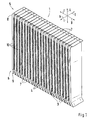
- a fin / tube block 1 of a heat exchanger 2 includes a plurality of tubes 3 stacked on each other in a width direction B of the fin / tube block 1.
- this width direction B of the ribs / tube block 1 corresponds to a depth direction t of the individual tubes 3.
- Corresponding corrugated ribs 4 are arranged between adjacent tubes 3, which flow through the ribs / tube block 1 in a depth direction T of the ribs / tube block 1 while flowing around the tubes 3 allows.
- the depth direction T of the ribs / tube block 1 extends parallel to the width directions b of the individual tubes 3.
- the individual tubes 3 are flat tubes, which preferably have a rectangular cross section but can also have a Arenenformquerites.
- the tubes 3 may be longitudinally welded or extruded.
- the ribs / tube block 1 In a longitudinal direction L of the ribs / tube block 1, which runs parallel to the longitudinal directions I of the individual tubes 3, the ribs / tube block 1 has two mutually remote edge sides 5 and 6.
- each tube 3 In these edge sides 5, 6, each tube 3 has a tube end region 7.
- At least at one of these edge sides 5, 6, preferably at both edge sides 5, 6, all Rohrend Schemee 7 are expanded and joined together flat to a Rohrendplex 8 or 9.
- the pipe end regions 7 are widened in the respective pipe depth direction t, in each case with respect to a pipe longitudinal region 10 of the respective pipe 3 lying between two pipe end regions 7, so that they adjoin one another in the block width direction B.
- all tube end regions 7 of the respective tube end package 8 or 9 are each inclined relative to the respective tube longitudinal direction I.
- all Rohrend Schemee 7 incline within the respective Rohrendvons 8 and 9 in the same direction and at right angles.
- the inclination of the Rohrend Gebe 7 takes place in each case to a non-illustrated bending axis, which is perpendicular to the ribs / tube block 1, that is parallel to the block depth direction T or parallel to the respective tube width direction b.
- the respective Rohrend Siemense 7 are widened in the tube depth direction t while they are retracted in the tube width direction b.
- the intake and the widening of the pipe end regions 7 can be coordinated with one another such that a free flow cross section in the respective pipe end region 7 is approximately the same as in the pipe longitudinal region 10 of the respective pipe 3. In this way, flow resistances can be reduced by changes in the cross section.
- the deformation of the pipe end regions 7 also takes place in such a way that the free ends of the pipe end regions 7 each lie approximately in a plane which runs parallel to the block width direction B and parallel to the block depth direction T.
- the respective level is indicated in FIGS. 3 and 4 by a dash-dotted line and denoted by 11.
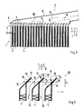
- the heat exchanger 2 comprises, in addition to the ribs / tube block 1, at least one collecting box 12 which is arranged on one of the edge sides 5 and 6, respectively.
- a collection box 12 is arranged on both edge sides 5 and 6, wherein the two header boxes 12 may be designed quite differently.
- the respective collection box 12 is placed on the associated Rohrendvers 8 or 9 and connected to this tight.
- a liquid or gaseous heat transfer medium is supplied to the fins / tube block 1 during operation of the heat exchanger 2.
- the inflow is symbolized in FIG. 5 by solid arrows and denoted by 13.
- the respective heat transfer medium from the fins / tube block 1 can be discharged in another flow direction through the collecting box 12.
- the corresponding outflow is indicated in Fig. 5 with broken arrows and designated 14.
- the inclination of the pipe end regions 7 takes place in the direction of a flow direction prevailing in the collecting box 12. This allows the flow resistance during deflection of the inflow 13 and the outflow 14 at the transition between the collection box 12 and ribs / tube block 1 can be reduced.
- the total deflection between the collection box 12 and ribs / tube block 1 is about 90 °.
- the deflection of the flow 13 is divided by the collection box 12 in the ribs / tube block 1 at the Rohrend Schemeen 7 in two partial deflections, both of which are each smaller than 90 °.
- the Rohrend Schemee 7 are inclined relative to the pipe longitudinal regions 10 in an angular range of about 30 ° to 60 ° relative to the associated pipe longitudinal regions 10.
- Preferred as in here shown representations is an inclination between Rohrend Schemeen 7 and associated pipe longitudinal portions 10 of about 45 °.
- each tube end region 7 has a first tube wall 15 and an opposite second tube wall 16 in the tube depth direction t.
- this pipe walls 15, 16 are the adjacent Rohrend Stude 7 to each other flat.
- the pipe end regions 7 are shaped such that an end edge 17 of the first pipe wall 15 with respect to the inflow 13 is arranged upstream of an end edge 18 of the second pipe wall 16.
- the end edge 18 of the second tube wall 16 is then arranged upstream of the end edge 17 of the first tube wall 15.
- the construction with respect to the flow direction 13, 14 staggered end edges 17, 18 leads to a sharp-edged separation between adjacent pipes 3.
- the transition between the collection box 12 and ribs / tube block 1 is then carried out for the heat transfer medium with a reduced resistance.
- the heat exchanger 2 is part of a cooling system, not shown here, preferably a motor vehicle.
- the heat exchanger 2 is a water cooler, oil cooler or intercooler through which cooling air can flow in the region of the corrugated fins 4.
- the heat exchanger 2 can be a heater or cooler through which fresh air and / or circulating air can flow in the region of the corrugated fins 4 for the temperature control of air fed into a vehicle interior.
Abstract
Description
Die vorliegende Erfindung betrifft einen Rippen/Rohrblock für einen Wärmeübertrager, insbesondere eines Kraftfahrzeugs, mit den Merkmalen des Oberbegriffs des Anspruchs 1. Die Erfindung betrifft außerdem einen mit einem derartigen Rippen/Rohrblock ausgestatteten Wärmeübertrager.The present invention relates to a rib / tube block for a heat exchanger, in particular a motor vehicle, having the features of the preamble of
Aus der
Ein weiterer Wärmeübertrager ist aus der
Die vorliegende Erfindung beschäftigt sich mit dem Problem, für einen Rippen/Rohrblock der eingangs genannten Art bzw. für einen damit ausgestatteten Wärmeübertrager eine verbesserte Ausführungsform anzugeben, die sich insbesondere durch eine verbesserte Herstellbarkeit und vorzugsweise durch eine verbesserte Durchströmung mit einem Wärmeübertragungsmedium auszeichnet.The present invention is concerned with the problem of providing for a rib / tube block of the type mentioned or for a heat exchanger equipped therewith an improved embodiment, which is characterized in particular by improved manufacturability and preferably by improved flow with a heat transfer medium.
Dieses Problem wird erfindungsgemäß durch die Gegenstände der unabhängigen Ansprüche gelöst. Vorteilhafte Ausführungsformen sind Gegenstand der abhängigen Ansprüche.This problem is solved according to the invention by the subject matters of the independent claims. Advantageous embodiments are the subject of the dependent claims.
Die vorliegende Erfindung beruht auf dem allgemeinen Gedanken, die Rohrendbereiche gegenüber der jeweiligen Rohrlängsrichtung geneigt auszurichten. Durch diese Bauweise kann der Rippen/Rohrblock während der Herstellung leichter gehandhabt werden, da die in der Breitenrichtung des Rippen/Rohrblocks bzw. in der Tiefenrichtung der einzelnen Rohre gestapelten Rohre in der Längsrichtung des Rippen/Rohrblocks, die parallel zu den Längsrichtungen der einzelnen Rohre verläuft, zumindest unidirektional formschlüssig in den Rohrendbereichen aneinander anliegen.The present invention is based on the general idea to align the Rohrendbereiche inclined relative to the respective pipe longitudinal direction. By this construction, the ribs / tube block can be handled more easily during the production because the tubes stacked in the width direction of the rib / tube block and in the depth direction of the individual tubes in the longitudinal direction of the rib / tube block parallel to the longitudinal directions of the individual tubes runs, at least unidirectionally form-fit in the Rohrendbereichen abut each other.
Gleichzeitig kann mit dieser Bauweise der Strömungswiderstand beim Übergang vom Sammelkasten in den Rippen/Rohrblock bzw. vom Rippen/Rohrblock in den Sammelkasten reduziert werden, wenn die Neigung der Rohrendbereiche entsprechend der jeweiligen Strömungsumlenkung orientiert ist. Zwar muss die Strömung zwischen dem jeweiligen Sammelkasten und den zwischen den Rohrendbereichen liegenden Rohrlängsbereichen des Rippen/Rohrblocks nach wie vor um etwa 90° umgelenkt werden, jedoch erfolgt diese Umlenkung nunmehr in zwei Schritten, die jeweils kleiner als 90° sind. Die erste Umlenkung erfolgt am Übergang zwischen Sammelkasten und Rohrendbereich. Der zweite Übergang erfolgt dann beim Übergang zwischen Rohrendbereich und Rohrlängsbereich. Entsprechendes gilt für die aus dem Rippen/Rohrblock austretende Strömung.At the same time can be reduced with this construction, the flow resistance in the transition from the collecting box in the ribs / tube block or from the ribs / tube block in the collection box, if the inclination of the Rohrendbereiche is oriented according to the respective flow deflection. Although the flow between the respective collection box and the tube longitudinal areas of the rib / tube block located between the pipe end areas must still be deflected by about 90 °, this deflection now takes place in two steps, each of which is less than 90 °. The first deflection takes place at the transition between collecting tank and pipe end area. The second transition then takes place at the transition between the pipe end region and the pipe longitudinal region. The same applies to the emerging from the ribs / tube block flow.
Entsprechend einer vorteilhaften Ausführungsform kann bei benachbarten Rohrendbereichen jeweils eine erste Rohrwand des einen Rohrendbereichs an eine zweite Rohrwand des anderen Rohrendbereichs flächig so anschließen, dass eine Endkante der einen Rohrwand stromauf einer Endkante der anderen Rohrwand angeordnet ist.According to an advantageous embodiment, in adjacent Rohrendbereichen each have a first pipe wall of a Rohrendbereichs to a second pipe wall of the other Rohrendbereichs area connect so that an end edge of a pipe wall upstream of an end edge of the other pipe wall is arranged.
Hierdurch ergibt sich eine scharfkantige Trennung am Einlauf bzw. am Auslauf benachbarter Rohre, was strömungstechnisch von Vorteil sein kann.This results in a sharp-edged separation at the inlet or at the outlet of adjacent tubes, which can be advantageous in terms of flow.
Weitere wichtige Merkmale und Vorteile der Erfindung ergeben sich aus den Unteransprüchen, aus den Zeichnungen und aus der zugehörigen Figurenbeschreibung anhand der Zeichnungen.Other important features and advantages of the invention will become apparent from the dependent claims, from the drawings and from the associated figure description with reference to the drawings.
Es versteht sich, dass die vorstehend genannten und die nachstehend noch zu erläuternden Merkmale nicht nur in der jeweils angegebenen Kombination, sondern auch in anderen Kombinationen oder in Alleinstellung verwendbar sind, ohne den Rahmen der vorliegenden Erfindung zu verlassen.It is understood that the features mentioned above and those yet to be explained below can be used not only in the particular combination given, but also in other combinations or in isolation, without departing from the scope of the present invention.
Bevorzugte Ausführungsbeispiele der Erfindung sind in den Zeichnungen dargestellt und werden in der nachfolgenden Beschreibung näher erläutert, wobei sich gleiche Bezugszeichen auf gleiche oder ähnliche oder funktional gleiche Bauteile beziehen.Preferred embodiments of the invention are illustrated in the drawings and will be described in more detail in the following description, wherein like reference numerals refer to the same or similar or functionally identical components.
Es zeigen, jeweils schematisch,
- Fig. 1
- eine perspektivische Ansicht auf einen Rippen/Rohrblock,
- Fig. 2
- eine vergrößerte perspektivische Ansicht auf einen Detail im Bereich einer Randseite des Rippen/Rohrblocks,
- Fig. 3
- eine Seitenansicht auf den Rippen/Rohrblock,
- Fig. 4
- eine Ansicht wie in Fig. 3, jedoch bei einer anderen Ausführungsform,
- Fig. 5
- eine vereinfachte Schnittansicht eines Wärmeübertragers im Bereich einer Randseite,
- Fig. 6
- ein vergrößertes Detail VI aus Fig. 5.
- Fig. 1
- a perspective view of a rib / tube block,
- Fig. 2
- an enlarged perspective view of a detail in the region of an edge side of the rib / tube block,
- Fig. 3
- a side view of the ribs / tube block,
- Fig. 4
- a view as in Fig. 3, but in another embodiment,
- Fig. 5
- a simplified sectional view of a heat exchanger in the region of an edge side,
- Fig. 6
- an enlarged detail VI of FIG. 5.
Entsprechend Fig. 1 umfasst ein Rippen/Rohrblock 1 eines Wärmeübertragers 2 (vgl. Fig. 5) mehrere Rohre 3, die in einer Breitenrichtung B des Rippen/Rohrblocks 1 aufeinander gestapelt sind. Dabei entspricht diese Breitenrichtung B des Rippen/Rohrblocks 1 einer Tiefenrichtung t der einzelnen Rohre 3. Zwischen benachbarten Rohren 3 sind jeweils Wellrippen 4 angeordnet, die eine Durchströmung des Rippen/Rohrblocks 1 in einer Tiefenrichtung T des Rippen/Rohrblocks 1 unter Umströmung der Rohre 3 ermöglicht. Dabei erstreckt sich die Tiefenrichtung T des Rippen/Rohrblocks 1 parallel zu den Breitenrichtungen b der einzelnen Rohre 3. Die einzelnen Rohre 3 sind dabei Flachrohre, die vorzugsweise einen Rechteckquerschnitt aufweisen aber auch einen Arenenformquerschnitt aufweisen können. Die Rohre 3 können längsnahtgeschweißt oder extrudiert sein.1, a fin /
In einer Längsrichtung L des Rippen/Rohrblocks 1, die parallel zu Längsrichtungen I der einzelnen Rohre 3 verläuft, besitzt der Rippen/Rohrblock 1 zwei voneinander entfernte Randseiten 5 bzw. 6. In diesen Randseiten 5, 6 besitzt jedes Rohr 3 einen Rohrendbereich 7. Zumindest an einer dieser Randseiten 5, 6, vorzugsweise an beiden Randseiten 5, 6, sind alle Rohrendbereiche 7 aufgeweitet und flächig aneinander anschließend zu einem Rohrendpaket 8 bzw. 9 zusammengefügt. Die Rohrendbereiche 7 sind dabei in der jeweiligen Rohrtiefenrichtung t jeweils bezüglich eines zwischen zwei Rohrendbereichen 7 liegenden Rohrlängsbereichs 10 des jeweiligen Rohrs 3 aufgeweitet, so dass sie in der Blockbreitenrichtung B aneinanderliegen. Entsprechend den Fig. 1 und 2 sind zumindest an einer Randseite 5 oder 6, vorzugsweise an beiden Randseiten 5 und 6, alle Rohrendbereiche 7 des jeweiligen Rohrendpakets 8 bzw. 9 jeweils gegenüber der jeweiligen Rohrlängsrichtung I geneigt. Dabei neigen sich sämtliche Rohrendbereiche 7 innerhalb des jeweiligen Rohrendpakets 8 bzw. 9 gleichsinnig und gleichwinklig. Die Neigung der Rohrendbereiche 7 erfolgt dabei jeweils um eine nicht eingezeichnete Biegeachse, die senkrecht auf dem Rippen/Rohrblock 1 steht, also parallel zur Blocktiefenrichtung T bzw. parallel zur jeweiligen Rohrbreitenrichtung b verläuft. Durch die Neigung der Rohrendbereiche 7 innerhalb des Rohrendpakets 8 bzw. 9 ergibt sich in der Blocklängsrichtung L bzw. in den Rohlängsrichtungen I eine formschlüssige Anlage benachbarter Rohrendbereiche 7 aneinander, zumindest unidirektional.In a longitudinal direction L of the ribs /
Sofern wie hier in beiden Rohrendpaketen 8, 9 die Rohrendbereiche 7 gegenüber den Rohrlängsbereichen 10 geneigt sind, ist es grundsätzlich entsprechend den Fig. 1 und 3 möglich, die Rohrendbereiche 7 des einen Rohrendpakets 8 und die Rohrendbereiche 7 des anderen Rohrendpakets 9 gleichsinnig gegenüber den Rohrlängsbereichen 10 zu neigen. Hierdurch ergibt sich für das jeweilige Rohr 3 in Rohrbreitenrichtung b eine C-Form. Bei dieser Ausführungsform sind die einzelnen Rohre 3 innerhalb des Rippen/Rohrblocks 1 in der Rohrlängsrichtung I an den Rohrendbereichen 7 bidirektional formschlüssig aneinander angeordnet, was die Handhabung des Rippen/Rohrblocks 1 während seiner Herstellung zusätzlich vereinfacht.If, as here in both Rohrendpaketen 8, 9, the
Im Unterschied dazu können entsprechend Fig. 4 die Rohrendbereiche 7 des einen Rohrendpakets 8 und die Rohrendbereiche 7 des anderen Rohrendpakets 9 gegensinnig gegenüber den Rohrlängsbereichen 10 geneigt sein, wodurch sich für das jeweilige Rohr 3 in der Rohrbreitenrichtung b eine S-Form ergibt.In contrast, according to Fig. 4, the
Entsprechend Fig. 2 sind die jeweiligen Rohrendbereiche 7 in der Rohrtiefenrichtung t aufgeweitet, während sie gleichzeitig in der Rohrbreitenrichtung b eingezogen sind. Der Einzug und die Aufweitung der Rohrendbereiche 7 können dabei so aufeinander abgestimmt sein, dass ein freier Strömungsquerschnitt im jeweiligen Rohrendbereich 7 etwa gleich groß ist wie im Rohrlängsbereich 10 des jeweiligen Rohrs 3. Hierdurch können Strömungswiderstände durch Querschnittsänderungen reduziert werden.According to Fig. 2, the
Die Umformung der Rohrendbereiche 7 erfolgt außerdem so, dass die freien Enden der Rohrendbereiche 7 jeweils etwa in einer Ebene liegen, die parallel zur Blockbreitenrichtung B und parallel zur Blocktiefenrichtung T verläuft. Die jeweilige Ebene ist in den Fig. 3 und 4 durch eine strichpunktierte Linie angedeutet und mit 11 bezeichnet.The deformation of the
Entsprechend Fig. 5 umfasst der Wärmeübertrager 2 neben dem Rippen/Rohrblock 1 zumindest einen Sammelkasten 12, der an einer der Randseiten 5 bzw. 6 angeordnet ist. Vorzugsweise ist an beiden Randseiten 5 und 6 ein derartiger Sammelkasten 12 angeordnet, wobei die beiden Sammelkästen 12 durchaus unterschiedlich ausgestaltet sein können. Dabei ist der jeweilige Sammelkasten 12 auf das zugeordnete Rohrendpaket 8 bzw. 9 aufgesetzt und mit diesem dicht verbunden. Durch den jeweiligen Sammelkasten 12 wird im Betrieb des Wärmeübertragers 2 dem Rippen/Rohrblock 1 ein flüssiges oder gasförmiges Wärmeübertragungsmedium zugeführt. Die Zuströmung ist in Fig. 5 mit durchgezogenen Pfeilen symbolisiert und mit 13 bezeichnet. In gleicher Weise ist bei anderer Strömungsrichtung durch den Sammelkasten 12 das jeweilige Wärmeübertragungsmedium vom Rippen/Rohrblock 1 abführbar. Die entsprechende Abströmung ist in Fig. 5 mit unterbrochenen Pfeilen angedeutet und mit 14 bezeichnet. Vorzugsweise erfolgt die Neigung der Rohrendbereiche 7 in Richtung einer im Sammelkasten 12 vorherrschenden Strömungsrichtung. Hierdurch kann der Strömungswiderstand beim Umlenken der Zuströmung 13 bzw. der Abströmung 14 beim Übergang zwischen Sammelkasten 12 und Rippen/Rohrblock 1 reduziert werden.According to FIG. 5, the
Bei einer Zuströmung 13 bzw. bei einer Abströmung 14, die jeweils im wesentlichen parallel zur Blockbreitenrichtung B erfolgt, beträgt die Gesamtumlenkung zwischen Sammelkasten 12 und Rippen/Rohrblock 1 etwa 90°. Entsprechend Fig. 6 wird die Umlenkung der Strömung 13 vom Sammelkasten 12 in den Rippen/Rohrblock 1 an den Rohrendbereichen 7 in zwei Teilumlenkungen unterteilt, die beide jeweils kleiner als 90° sind. Entsprechendes gilt auch für die Umlenkung der Abströmung 14 beim Übergang vom Rippen/Rohrblock 1 zum Sammelkasten 12. Zweckmäßig sind die Rohrendbereiche 7 gegenüber den Rohrlängsbereichen 10 in einem Winkelbereich von etwa 30° bis 60° gegenüber den zugehörigen Rohrlängsbereichen 10 geneigt. Bevorzugt wie in den hier gezeigten Darstellungen ist eine Neigung zwischen Rohrendbereichen 7 und zugehörigen Rohrlängsbereichen 10 von etwa 45°.In an
Entsprechend Fig. 6 weist jeder Rohrendbereich 7 in der Rohrtiefenrichtung t jeweils eine erste Rohrwand 15 und eine gegenüberliegende zweite Rohrwand 16 auf. Über diese Rohrwände 15, 16 liegen die benachbarten Rohrendbereiche 7 aneinander flächig an. Bei der hier gezeigten, bevorzugten Ausführungsform sind die Rohrendbereiche 7 so geformt, dass eine Endkante 17 der ersten Rohrwand 15 bezüglich der Zuströmung 13 stromauf einer Endkante 18 der zweiten Rohrwand 16 angeordnet ist. Bei der Abströmung 14 ist dann die Endkante 18 der zweiten Rohrwand 16 stromauf der Endkante 17 der ersten Rohrwand 15 angeordnet. Die Bauweise mit bezüglich der Strömungsrichtung 13, 14 zueinander versetzt angeordneten Endkanten 17, 18 führt zu einer scharfkantigen Abtrennung zwischen benachbarten Rohren 3. Der Übergang zwischen Sammelkasten 12 und Rippen/Rohrblock 1 erfolgt für das Wärmeübertragungsmedium dann mit einem reduzierten Widerstand.According to FIG. 6, each
Der Wärmeübertrager 2 ist Bestandteil eines hier nicht gezeigten Kühlsystems, vorzugsweise eines Kraftfahrzeugs. Beispielsweise handelt es sich beim Wärmeübertrager 2 um einen im Bereich der Wellrippen 4 mit Kühlluft durchströmbaren Wasserkühler, Ölkühler oder Ladeluftkühler. Ebenso kann es sich beim Wärmeübertrager 2 um einen im Bereich der Wellrippen 4 mit Frischluft und/oder Umluft durchströmbaren Heizer oder Kühler zum Temperieren von einem Fahrzeuginnenraum zugeführter Luft handeln.The
Claims (9)
dadurch gekennzeichnet,
dass alle Rohrendbereiche (7) des Rohrendpakets (8, 9) jeweils gegenüber der jeweiligen Rohrlängsrichtung (I) geneigt sind.Ribs / tube block for a heat exchanger (2), in particular of a motor vehicle, in which at least at one edge side (5, 6) all the tube end regions (7) are widened and joined together flatly to form a tube end packet (8, 9),
characterized,
that all Rohrendbereiche (7) of the Rohrendpakets (8, 9) are each inclined relative to the respective pipe longitudinal direction (I).
dadurch gekennzeichnet,
dass bei benachbarten Rohrendbereichen (7) jeweils eine erste Rohrwand (15) des einen Rohrendbereichs (7) an eine zweite Rohrwand (16) des anderen Rohrendbereichs (7) flächig anschließt, derart, dass eine Endkante (17 oder 18) der einen Rohrwand (15 oder 16) stromauf einer Endkante (18 oder 17) der anderen Rohrwand (16 oder 15) angeordnet ist.Ribs / tube block according to claim 1,
characterized,
that at adjacent pipe end (7) in each case a first tube wall (15) of connecting a pipe end (7) to a second tube wall (16) of the other pipe end (7) surface, such that an end edge (17 or 18) of (a tube wall 15 or 16) upstream of one end edge (18 or 17) of the other tube wall (16 or 15).
dadurch gekennzeichnet,
dass das jeweilige Rohrendpaket (8, 9) in einem Sammelkasten (12) angeordnet ist, durch den ein flüssiges oder gasförmiges Wärmeübertragungsmedium dem Rippen/Rohrblock (1) zuführbar oder vom Rippen/Rohrblock (1) abführbar ist.Ribs / tube block according to claim 1,
characterized,
that the respective Rohrendpaket (8, 9) is arranged in a collecting box (12) through which is discharged a liquid or gaseous heat transfer medium to the fin / tube block (1) supplied to or from the fin / tube block (1).
dadurch gekennzeichnet,
dass die Rohrendbereiche (7) in Richtung einer im Sammelkasten (12) vorherrschenden Strömungsrichtung (13, 14) des Wärmeübertragungsmedium gegenüber der jeweiligen Rohrlängsrichtung (I) geneigt sind.Ribs / tube block according to claim 3,
characterized,
in that the pipe end regions (7) are inclined in the direction of a flow direction (13, 14) of the heat transfer medium prevailing in the collecting box (12) with respect to the respective pipe longitudinal direction (I).
dadurch gekennzeichnet,
dass die Rohrendbereiche (7) gegenüber der jeweiligen Rohrlängsrichtung (I) um etwa 30° bis 60° oder um etwa 45° geneigt sind.Ribs / tube block according to one of claims 1 to 4,
characterized,
that the tube end (7) opposite to the respective tube longitudinal direction (I) are inclined by about 30 ° to 60 ° or approximately 45 °.
dadurch gekennzeichnet,
dass der Rippen/Rohrblock (1) an beiden gegenüberliegenden oder an mindestens einer Randseite (5, 6) jeweils ein solches Rohrendpaket (8, 9) aufweist.Ribs / tube block according to one of claims 1 to 5,
characterized,
that the ribs / tube block (1) at both opposite or at least one edge side (5, 6) in each case such a Rohrendpaket (8, 9).
dadurch gekennzeichnet,
dass die Rohrendbereiche (7) des einen Rohrendpakets (8) und die Rohrendbereiche (7) des anderen Rohrendpakets (9) gleichsinnig oder gegensinnig gegenüber der jeweiligen Rohrlängsrichtung (I) geneigt sind.Ribs / tube block according to claim 6,
characterized,
that the tube end (7) of a Rohrendpakets (8) and the tube end (7) of the other Rohrendpakets (9) (I) are the same direction or in opposite directions relative to the respective tube longitudinal direction inclined.
dadurch gekennzeichnet,
dass die Rohrendbereiche (7) in einer Tiefenrichtung (t) zugehöriger Rohre (3) aufgeweitet sind und in einer Breitenrichtung (b) der Rohre (3) eingezogen sind, derart, dass ein freier Strömungsquerschnitt im jeweiligen Rohrendbereich (7) und im zugehörigen Rohr (3) etwa gleich groß ist.Ribs / tube block according to one of claims 1 to 7,
characterized,
in that the tube end regions (7) are widened in a depth direction (t) of associated tubes (3) and retracted in a width direction (b) of the tubes (3), such that a free flow cross-section in the respective tube end region (7) and in the associated tube (3) is about the same size.
Applications Claiming Priority (1)
| Application Number | Priority Date | Filing Date | Title |
|---|---|---|---|
| DE102005038510A DE102005038510A1 (en) | 2005-07-30 | 2005-07-30 | Ribs / tube block for a heat exchanger |
Publications (2)
| Publication Number | Publication Date |
|---|---|
| EP1748271A1 true EP1748271A1 (en) | 2007-01-31 |
| EP1748271B1 EP1748271B1 (en) | 2008-01-23 |
Family
ID=37441775
Family Applications (1)
| Application Number | Title | Priority Date | Filing Date |
|---|---|---|---|
| EP06009625A Expired - Fee Related EP1748271B1 (en) | 2005-07-30 | 2006-05-10 | Fins and tubes for a heat exchanger core |
Country Status (3)
| Country | Link |
|---|---|
| EP (1) | EP1748271B1 (en) |
| AT (1) | ATE384926T1 (en) |
| DE (2) | DE102005038510A1 (en) |
Cited By (3)
| Publication number | Priority date | Publication date | Assignee | Title |
|---|---|---|---|---|
| WO2011154241A1 (en) | 2010-06-10 | 2011-12-15 | Rolls-Royce Plc | A heat exchanger |
| FR2992713A1 (en) * | 2012-06-29 | 2014-01-03 | Valeo Systemes Thermiques | Beam for heat exchanger of car, has tubes stacked in stacking direction, where tubes include raised portions that are in contact with each other by stack of tubes, so as to form partition wall of fluids for manifold of heat exchanger |
| EP2906896A4 (en) * | 2012-06-28 | 2016-07-27 | Cooper Standard Automotive Inc | Heat exchanger |
Families Citing this family (1)
| Publication number | Priority date | Publication date | Assignee | Title |
|---|---|---|---|---|
| DE102017107134A1 (en) | 2017-04-03 | 2018-10-04 | Dr. Ing. H.C. F. Porsche Aktiengesellschaft | Heat exchanger for high temperature application, in particular intercooler |
Citations (4)
| Publication number | Priority date | Publication date | Assignee | Title |
|---|---|---|---|---|
| JPH09250894A (en) * | 1996-03-14 | 1997-09-22 | Calsonic Corp | Heat exchanger |
| DE19722099A1 (en) | 1997-03-11 | 1998-09-17 | Behr Gmbh & Co | Heat exchanger for a motor vehicle |
| EP0881447A2 (en) * | 1997-05-27 | 1998-12-02 | Behr GmbH & Co. | Heat exchanger and heat exchanging apparatus for vehicle |
| EP1574802A2 (en) * | 2004-03-13 | 2005-09-14 | Dr.Ing. h.c.F. Porsche Aktiengesellschaft | Heat exchanger, more particularly charged air cooler for automotive vehicle |
Family Cites Families (5)
| Publication number | Priority date | Publication date | Assignee | Title |
|---|---|---|---|---|
| DE19743427B4 (en) * | 1997-10-01 | 2007-05-03 | Behr Gmbh & Co. Kg | Heat exchanger |
| DE19820937A1 (en) * | 1998-05-09 | 1999-11-11 | Behr Gmbh & Co | Flat tube for heat exchanger in vehicle cooling system |
| DE10033070A1 (en) * | 2000-03-31 | 2002-01-17 | Modine Mfg Co | Radiators for motor vehicles and manufacturing processes |
| DE10132153A1 (en) * | 2001-07-03 | 2003-01-23 | Modine Mfg Co | Heat exchanger for motor vehicles comprises a block consisting of flat tubes arranged in a row which are directly connected on a narrow side to the narrow side of the flat tubes of a second adjacent row |
| DE102004003047A1 (en) * | 2004-01-20 | 2005-08-11 | Behr Gmbh & Co. Kg | Heat exchanger, in particular coolant or intercooler for motor vehicles |
-
2005
- 2005-07-30 DE DE102005038510A patent/DE102005038510A1/en not_active Withdrawn
-
2006
- 2006-05-10 DE DE502006000310T patent/DE502006000310D1/en active Active
- 2006-05-10 EP EP06009625A patent/EP1748271B1/en not_active Expired - Fee Related
- 2006-05-10 AT AT06009625T patent/ATE384926T1/en not_active IP Right Cessation
Patent Citations (5)
| Publication number | Priority date | Publication date | Assignee | Title |
|---|---|---|---|---|
| JPH09250894A (en) * | 1996-03-14 | 1997-09-22 | Calsonic Corp | Heat exchanger |
| DE19722099A1 (en) | 1997-03-11 | 1998-09-17 | Behr Gmbh & Co | Heat exchanger for a motor vehicle |
| EP0881447A2 (en) * | 1997-05-27 | 1998-12-02 | Behr GmbH & Co. | Heat exchanger and heat exchanging apparatus for vehicle |
| EP0881447B1 (en) | 1997-05-27 | 2004-08-18 | Behr GmbH & Co. | Heat exchanger and heat exchanging apparatus for vehicle |
| EP1574802A2 (en) * | 2004-03-13 | 2005-09-14 | Dr.Ing. h.c.F. Porsche Aktiengesellschaft | Heat exchanger, more particularly charged air cooler for automotive vehicle |
Cited By (4)
| Publication number | Priority date | Publication date | Assignee | Title |
|---|---|---|---|---|
| WO2011154241A1 (en) | 2010-06-10 | 2011-12-15 | Rolls-Royce Plc | A heat exchanger |
| US9733026B2 (en) | 2010-06-10 | 2017-08-15 | Rolls Royce Plc | Heat exchanger with fluid guiding members |
| EP2906896A4 (en) * | 2012-06-28 | 2016-07-27 | Cooper Standard Automotive Inc | Heat exchanger |
| FR2992713A1 (en) * | 2012-06-29 | 2014-01-03 | Valeo Systemes Thermiques | Beam for heat exchanger of car, has tubes stacked in stacking direction, where tubes include raised portions that are in contact with each other by stack of tubes, so as to form partition wall of fluids for manifold of heat exchanger |
Also Published As
| Publication number | Publication date |
|---|---|
| ATE384926T1 (en) | 2008-02-15 |
| DE502006000310D1 (en) | 2008-03-13 |
| EP1748271B1 (en) | 2008-01-23 |
| DE102005038510A1 (en) | 2007-02-01 |
Similar Documents
| Publication | Publication Date | Title |
|---|---|---|
| DE60011616T2 (en) | HEAT EXCHANGER WITH MULTICHANNEL TUBES | |
| DE69911131T2 (en) | heat exchangers | |
| EP1279805B1 (en) | Air-cooled intake air cooler | |
| EP0964218B1 (en) | Heat exchanger with flat finned tubes, more particularly radiator,cooler,condenser or evaporator for automotive vehicle | |
| DE102005010493A1 (en) | Heat exchanger with flat tubes and flat heat exchanger tube | |
| EP0881447A2 (en) | Heat exchanger and heat exchanging apparatus for vehicle | |
| DE102007028792A1 (en) | heat exchangers | |
| DE2952736C2 (en) | ||
| DE4432972A1 (en) | Heat exchanger having two rows of tubes (pipes), in particular for motor vehicles | |
| EP1203922A2 (en) | Condenser and tube therefor | |
| EP1657512B1 (en) | Heat exchanger with open profile as housing | |
| EP1411310B1 (en) | Heat exhanger with serpentine structure | |
| EP1640684A1 (en) | heat exchanger with flat tubes and corrugated fins | |
| EP1748271B1 (en) | Fins and tubes for a heat exchanger core | |
| DE102015209130A1 (en) | Heat exchanger | |
| WO2012159958A1 (en) | Multiplate heat exchanger | |
| DE10342241A1 (en) | heat exchangers | |
| DE19547928C2 (en) | Plate heat exchanger | |
| EP1923654B1 (en) | Heat exchanger | |
| EP1934545A1 (en) | Heating body, cooling circuit, air conditioning unit for a motor vehicle air conditioning system, and air conditioning system for a motor vehicle | |
| EP0177904B1 (en) | Device for exchange of heat between two gases conducted in cross-flow to each other | |
| DE19814028A1 (en) | Integrated double heat exchanger | |
| EP2049859B1 (en) | Motor vehicle air conditioning system | |
| EP1923653B1 (en) | Heat exchanger | |
| EP1593536A2 (en) | Method of and arrangement for separating fluid streams in a heating device |
Legal Events
| Date | Code | Title | Description |
|---|---|---|---|
| PUAI | Public reference made under article 153(3) epc to a published international application that has entered the european phase |
Free format text: ORIGINAL CODE: 0009012 |
|
| AK | Designated contracting states |
Kind code of ref document: A1 Designated state(s): AT BE BG CH CY CZ DE DK EE ES FI FR GB GR HU IE IS IT LI LT LU LV MC NL PL PT RO SE SI SK TR |
|
| AX | Request for extension of the european patent |
Extension state: AL BA HR MK YU |
|
| 17P | Request for examination filed |
Effective date: 20070731 |
|
| GRAP | Despatch of communication of intention to grant a patent |
Free format text: ORIGINAL CODE: EPIDOSNIGR1 |
|
| AKX | Designation fees paid |
Designated state(s): AT DE ES FR GB IT |
|
| GRAS | Grant fee paid |
Free format text: ORIGINAL CODE: EPIDOSNIGR3 |
|
| GRAA | (expected) grant |
Free format text: ORIGINAL CODE: 0009210 |
|
| AK | Designated contracting states |
Kind code of ref document: B1 Designated state(s): AT DE ES FR GB IT |
|
| REG | Reference to a national code |
Ref country code: GB Ref legal event code: FG4D Free format text: NOT ENGLISH |
|
| REF | Corresponds to: |
Ref document number: 502006000310 Country of ref document: DE Date of ref document: 20080313 Kind code of ref document: P |
|
| GBT | Gb: translation of ep patent filed (gb section 77(6)(a)/1977) |
Effective date: 20080418 |
|
| RAP2 | Party data changed (patent owner data changed or rights of a patent transferred) |
Owner name: DR. ING. H.C. F. PORSCHE AKTIENGESELLSCHAFT |
|
| RAP2 | Party data changed (patent owner data changed or rights of a patent transferred) |
Owner name: DR. ING. H.C. F. PORSCHE AKTIENGESELLSCHAFT |
|
| PG25 | Lapsed in a contracting state [announced via postgrant information from national office to epo] |
Ref country code: ES Free format text: LAPSE BECAUSE OF FAILURE TO SUBMIT A TRANSLATION OF THE DESCRIPTION OR TO PAY THE FEE WITHIN THE PRESCRIBED TIME-LIMIT Effective date: 20080504 |
|
| ET | Fr: translation filed | ||
| PLBE | No opposition filed within time limit |
Free format text: ORIGINAL CODE: 0009261 |
|
| STAA | Information on the status of an ep patent application or granted ep patent |
Free format text: STATUS: NO OPPOSITION FILED WITHIN TIME LIMIT |
|
| 26N | No opposition filed |
Effective date: 20081024 |
|
| REG | Reference to a national code |
Ref country code: FR Ref legal event code: TP |
|
| PG25 | Lapsed in a contracting state [announced via postgrant information from national office to epo] |
Ref country code: AT Free format text: LAPSE BECAUSE OF NON-PAYMENT OF DUE FEES Effective date: 20080510 |
|
| REG | Reference to a national code |
Ref country code: FR Ref legal event code: CD |
|
| REG | Reference to a national code |
Ref country code: FR Ref legal event code: TP |
|
| REG | Reference to a national code |
Ref country code: GB Ref legal event code: 732E Free format text: REGISTERED BETWEEN 20110310 AND 20110316 |
|
| REG | Reference to a national code |
Ref country code: GB Ref legal event code: 732E Free format text: REGISTERED BETWEEN 20110331 AND 20110406 |
|
| PGFP | Annual fee paid to national office [announced via postgrant information from national office to epo] |
Ref country code: FR Payment date: 20110607 Year of fee payment: 6 |
|
| PGFP | Annual fee paid to national office [announced via postgrant information from national office to epo] |
Ref country code: GB Payment date: 20110520 Year of fee payment: 6 |
|
| PGFP | Annual fee paid to national office [announced via postgrant information from national office to epo] |
Ref country code: IT Payment date: 20110523 Year of fee payment: 6 |
|
| GBPC | Gb: european patent ceased through non-payment of renewal fee |
Effective date: 20120510 |
|
| PG25 | Lapsed in a contracting state [announced via postgrant information from national office to epo] |
Ref country code: IT Free format text: LAPSE BECAUSE OF NON-PAYMENT OF DUE FEES Effective date: 20120510 |
|
| REG | Reference to a national code |
Ref country code: FR Ref legal event code: ST Effective date: 20130131 |
|
| PG25 | Lapsed in a contracting state [announced via postgrant information from national office to epo] |
Ref country code: FR Free format text: LAPSE BECAUSE OF NON-PAYMENT OF DUE FEES Effective date: 20120531 Ref country code: GB Free format text: LAPSE BECAUSE OF NON-PAYMENT OF DUE FEES Effective date: 20120510 |
|
| PGFP | Annual fee paid to national office [announced via postgrant information from national office to epo] |
Ref country code: DE Payment date: 20190510 Year of fee payment: 14 |
|
| REG | Reference to a national code |
Ref country code: DE Ref legal event code: R119 Ref document number: 502006000310 Country of ref document: DE |
|
| PG25 | Lapsed in a contracting state [announced via postgrant information from national office to epo] |
Ref country code: DE Free format text: LAPSE BECAUSE OF NON-PAYMENT OF DUE FEES Effective date: 20201201 |