EP1746956B1 - Schwungphasensteuervorrichtung - Google Patents
Schwungphasensteuervorrichtung Download PDFInfo
- Publication number
- EP1746956B1 EP1746956B1 EP05736345A EP05736345A EP1746956B1 EP 1746956 B1 EP1746956 B1 EP 1746956B1 EP 05736345 A EP05736345 A EP 05736345A EP 05736345 A EP05736345 A EP 05736345A EP 1746956 B1 EP1746956 B1 EP 1746956B1
- Authority
- EP
- European Patent Office
- Prior art keywords
- chamber
- piston
- throttle
- phase control
- swing phase
- Prior art date
- Legal status (The legal status is an assumption and is not a legal conclusion. Google has not performed a legal analysis and makes no representation as to the accuracy of the status listed.)
- Expired - Lifetime
Links
- 239000012530 fluid Substances 0.000 claims abstract description 24
- 210000000629 knee joint Anatomy 0.000 claims abstract description 20
- 239000003570 air Substances 0.000 claims description 21
- 239000012080 ambient air Substances 0.000 claims description 8
- 230000033001 locomotion Effects 0.000 description 30
- 230000006835 compression Effects 0.000 description 9
- 238000007906 compression Methods 0.000 description 9
- 238000005452 bending Methods 0.000 description 6
- 238000013016 damping Methods 0.000 description 3
- 230000001419 dependent effect Effects 0.000 description 2
- 230000000694 effects Effects 0.000 description 2
- 210000003127 knee Anatomy 0.000 description 2
- 210000002414 leg Anatomy 0.000 description 2
- 239000007788 liquid Substances 0.000 description 2
- 210000000689 upper leg Anatomy 0.000 description 2
- 230000006978 adaptation Effects 0.000 description 1
- 238000011161 development Methods 0.000 description 1
- 230000018109 developmental process Effects 0.000 description 1
- 239000000428 dust Substances 0.000 description 1
- 238000007654 immersion Methods 0.000 description 1
- 238000000034 method Methods 0.000 description 1
- 238000007789 sealing Methods 0.000 description 1
- 230000007306 turnover Effects 0.000 description 1
Images




Classifications
-
- A—HUMAN NECESSITIES
- A61—MEDICAL OR VETERINARY SCIENCE; HYGIENE
- A61F—FILTERS IMPLANTABLE INTO BLOOD VESSELS; PROSTHESES; DEVICES PROVIDING PATENCY TO, OR PREVENTING COLLAPSING OF, TUBULAR STRUCTURES OF THE BODY, e.g. STENTS; ORTHOPAEDIC, NURSING OR CONTRACEPTIVE DEVICES; FOMENTATION; TREATMENT OR PROTECTION OF EYES OR EARS; BANDAGES, DRESSINGS OR ABSORBENT PADS; FIRST-AID KITS
- A61F2/00—Filters implantable into blood vessels; Prostheses, i.e. artificial substitutes or replacements for parts of the body; Appliances for connecting them with the body; Devices providing patency to, or preventing collapsing of, tubular structures of the body, e.g. stents
- A61F2/50—Prostheses not implantable in the body
- A61F2/68—Operating or control means
-
- A—HUMAN NECESSITIES
- A61—MEDICAL OR VETERINARY SCIENCE; HYGIENE
- A61F—FILTERS IMPLANTABLE INTO BLOOD VESSELS; PROSTHESES; DEVICES PROVIDING PATENCY TO, OR PREVENTING COLLAPSING OF, TUBULAR STRUCTURES OF THE BODY, e.g. STENTS; ORTHOPAEDIC, NURSING OR CONTRACEPTIVE DEVICES; FOMENTATION; TREATMENT OR PROTECTION OF EYES OR EARS; BANDAGES, DRESSINGS OR ABSORBENT PADS; FIRST-AID KITS
- A61F2/00—Filters implantable into blood vessels; Prostheses, i.e. artificial substitutes or replacements for parts of the body; Appliances for connecting them with the body; Devices providing patency to, or preventing collapsing of, tubular structures of the body, e.g. stents
- A61F2/50—Prostheses not implantable in the body
- A61F2/60—Artificial legs or feet or parts thereof
- A61F2/64—Knee joints
-
- A—HUMAN NECESSITIES
- A61—MEDICAL OR VETERINARY SCIENCE; HYGIENE
- A61F—FILTERS IMPLANTABLE INTO BLOOD VESSELS; PROSTHESES; DEVICES PROVIDING PATENCY TO, OR PREVENTING COLLAPSING OF, TUBULAR STRUCTURES OF THE BODY, e.g. STENTS; ORTHOPAEDIC, NURSING OR CONTRACEPTIVE DEVICES; FOMENTATION; TREATMENT OR PROTECTION OF EYES OR EARS; BANDAGES, DRESSINGS OR ABSORBENT PADS; FIRST-AID KITS
- A61F2/00—Filters implantable into blood vessels; Prostheses, i.e. artificial substitutes or replacements for parts of the body; Appliances for connecting them with the body; Devices providing patency to, or preventing collapsing of, tubular structures of the body, e.g. stents
- A61F2/50—Prostheses not implantable in the body
- A61F2/68—Operating or control means
- A61F2/74—Operating or control means fluid, i.e. hydraulic or pneumatic
-
- A—HUMAN NECESSITIES
- A61—MEDICAL OR VETERINARY SCIENCE; HYGIENE
- A61F—FILTERS IMPLANTABLE INTO BLOOD VESSELS; PROSTHESES; DEVICES PROVIDING PATENCY TO, OR PREVENTING COLLAPSING OF, TUBULAR STRUCTURES OF THE BODY, e.g. STENTS; ORTHOPAEDIC, NURSING OR CONTRACEPTIVE DEVICES; FOMENTATION; TREATMENT OR PROTECTION OF EYES OR EARS; BANDAGES, DRESSINGS OR ABSORBENT PADS; FIRST-AID KITS
- A61F2/00—Filters implantable into blood vessels; Prostheses, i.e. artificial substitutes or replacements for parts of the body; Appliances for connecting them with the body; Devices providing patency to, or preventing collapsing of, tubular structures of the body, e.g. stents
- A61F2/50—Prostheses not implantable in the body
- A61F2/68—Operating or control means
- A61F2/74—Operating or control means fluid, i.e. hydraulic or pneumatic
- A61F2/748—Valve systems
-
- A—HUMAN NECESSITIES
- A61—MEDICAL OR VETERINARY SCIENCE; HYGIENE
- A61F—FILTERS IMPLANTABLE INTO BLOOD VESSELS; PROSTHESES; DEVICES PROVIDING PATENCY TO, OR PREVENTING COLLAPSING OF, TUBULAR STRUCTURES OF THE BODY, e.g. STENTS; ORTHOPAEDIC, NURSING OR CONTRACEPTIVE DEVICES; FOMENTATION; TREATMENT OR PROTECTION OF EYES OR EARS; BANDAGES, DRESSINGS OR ABSORBENT PADS; FIRST-AID KITS
- A61F2/00—Filters implantable into blood vessels; Prostheses, i.e. artificial substitutes or replacements for parts of the body; Appliances for connecting them with the body; Devices providing patency to, or preventing collapsing of, tubular structures of the body, e.g. stents
- A61F2/50—Prostheses not implantable in the body
- A61F2002/5016—Prostheses not implantable in the body adjustable
- A61F2002/5021—Prostheses not implantable in the body adjustable for adjusting a position by translation along an axis
-
- A—HUMAN NECESSITIES
- A61—MEDICAL OR VETERINARY SCIENCE; HYGIENE
- A61F—FILTERS IMPLANTABLE INTO BLOOD VESSELS; PROSTHESES; DEVICES PROVIDING PATENCY TO, OR PREVENTING COLLAPSING OF, TUBULAR STRUCTURES OF THE BODY, e.g. STENTS; ORTHOPAEDIC, NURSING OR CONTRACEPTIVE DEVICES; FOMENTATION; TREATMENT OR PROTECTION OF EYES OR EARS; BANDAGES, DRESSINGS OR ABSORBENT PADS; FIRST-AID KITS
- A61F2/00—Filters implantable into blood vessels; Prostheses, i.e. artificial substitutes or replacements for parts of the body; Appliances for connecting them with the body; Devices providing patency to, or preventing collapsing of, tubular structures of the body, e.g. stents
- A61F2/50—Prostheses not implantable in the body
- A61F2002/5016—Prostheses not implantable in the body adjustable
- A61F2002/5032—Prostheses not implantable in the body adjustable for adjusting fluid pressure
-
- A—HUMAN NECESSITIES
- A61—MEDICAL OR VETERINARY SCIENCE; HYGIENE
- A61F—FILTERS IMPLANTABLE INTO BLOOD VESSELS; PROSTHESES; DEVICES PROVIDING PATENCY TO, OR PREVENTING COLLAPSING OF, TUBULAR STRUCTURES OF THE BODY, e.g. STENTS; ORTHOPAEDIC, NURSING OR CONTRACEPTIVE DEVICES; FOMENTATION; TREATMENT OR PROTECTION OF EYES OR EARS; BANDAGES, DRESSINGS OR ABSORBENT PADS; FIRST-AID KITS
- A61F2/00—Filters implantable into blood vessels; Prostheses, i.e. artificial substitutes or replacements for parts of the body; Appliances for connecting them with the body; Devices providing patency to, or preventing collapsing of, tubular structures of the body, e.g. stents
- A61F2/50—Prostheses not implantable in the body
- A61F2002/5016—Prostheses not implantable in the body adjustable
- A61F2002/5033—Prostheses not implantable in the body adjustable for adjusting damping
-
- A—HUMAN NECESSITIES
- A61—MEDICAL OR VETERINARY SCIENCE; HYGIENE
- A61F—FILTERS IMPLANTABLE INTO BLOOD VESSELS; PROSTHESES; DEVICES PROVIDING PATENCY TO, OR PREVENTING COLLAPSING OF, TUBULAR STRUCTURES OF THE BODY, e.g. STENTS; ORTHOPAEDIC, NURSING OR CONTRACEPTIVE DEVICES; FOMENTATION; TREATMENT OR PROTECTION OF EYES OR EARS; BANDAGES, DRESSINGS OR ABSORBENT PADS; FIRST-AID KITS
- A61F2/00—Filters implantable into blood vessels; Prostheses, i.e. artificial substitutes or replacements for parts of the body; Appliances for connecting them with the body; Devices providing patency to, or preventing collapsing of, tubular structures of the body, e.g. stents
- A61F2/50—Prostheses not implantable in the body
- A61F2002/5072—Prostheses not implantable in the body having spring elements
- A61F2002/5073—Helical springs, e.g. having at least one helical spring
- A61F2002/5075—Multiple spring systems including two or more helical springs
-
- A—HUMAN NECESSITIES
- A61—MEDICAL OR VETERINARY SCIENCE; HYGIENE
- A61F—FILTERS IMPLANTABLE INTO BLOOD VESSELS; PROSTHESES; DEVICES PROVIDING PATENCY TO, OR PREVENTING COLLAPSING OF, TUBULAR STRUCTURES OF THE BODY, e.g. STENTS; ORTHOPAEDIC, NURSING OR CONTRACEPTIVE DEVICES; FOMENTATION; TREATMENT OR PROTECTION OF EYES OR EARS; BANDAGES, DRESSINGS OR ABSORBENT PADS; FIRST-AID KITS
- A61F2/00—Filters implantable into blood vessels; Prostheses, i.e. artificial substitutes or replacements for parts of the body; Appliances for connecting them with the body; Devices providing patency to, or preventing collapsing of, tubular structures of the body, e.g. stents
- A61F2/50—Prostheses not implantable in the body
- A61F2002/5081—Additional features
- A61F2002/5087—Sound-damping or noise-reducing means
-
- A—HUMAN NECESSITIES
- A61—MEDICAL OR VETERINARY SCIENCE; HYGIENE
- A61F—FILTERS IMPLANTABLE INTO BLOOD VESSELS; PROSTHESES; DEVICES PROVIDING PATENCY TO, OR PREVENTING COLLAPSING OF, TUBULAR STRUCTURES OF THE BODY, e.g. STENTS; ORTHOPAEDIC, NURSING OR CONTRACEPTIVE DEVICES; FOMENTATION; TREATMENT OR PROTECTION OF EYES OR EARS; BANDAGES, DRESSINGS OR ABSORBENT PADS; FIRST-AID KITS
- A61F2250/00—Special features of prostheses classified in groups A61F2/00 - A61F2/26 or A61F2/82 or A61F9/00 or A61F11/00 or subgroups thereof
- A61F2250/0058—Additional features; Implant or prostheses properties not otherwise provided for
- A61F2250/0075—Sound-damping or noise-reducing means
Definitions
- the present invention relates to a swing phase control device for an artificial knee joint with a piston-cylinder device.
- Such a piston-cylinder device is for example from the EP 0 615 430 B1 known.
- the swing phase control device described therein has a first chamber on one side of the piston and a second chamber on the opposite side of the piston, wherein the two chambers are connectable to each other via a first throttle.
- a second throttle is provided for connecting the second chamber to a fluid reservoir, wherein a device is designed such that it closes when reaching or exceeding a predetermined pressure in the second chamber, the second throttle.
- the person using the artificial knee joint must swing the lower leg forward again and bring it into extension with the thigh.
- a predetermined throttling effect occurs, in which the throttling takes place via the first throttle and does not depend on the stretching speed of the artificial knee joint.
- the stretching process is dependent on the walking speed, such throttling leads to an unnatural movement.
- the first throttle is adjustable and can thus be adapted to the respective running style, but it has no dynamic adaptation to different movements of the person. So the first throttle only works optimally for either slow or fast movements.
- the momentum phase control according to the invention has the particular advantage that it also provides a throttling for the stretching movement, which is dependent on the speed of movement and can be set separately from the throttling of the bending movement. It is thus possible a movement sequence, the natural effect.
- a rapid stretching movement takes place, the piston moving out of the cylinder very rapidly reduces the volume of the first chamber and compresses the fluid contained therein.
- the first throttle is closed and damping by the compressed fluid occurs.
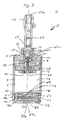
- the swing phase control device 1 has a cylinder piston device 2 with a cylinder 3 and a piston 12.
- the cylinder 3 comprises a tubular portion 5 with a lid part 4 at one end and a bottom part 6 at the opposite end.
- the cover part 4 has an inlet opening 7, which allows a connection between the ambient air and an inlet-side first chamber 8 formed in the cylinder 3.
- the inlet opening 7 is provided with a check valve 9 which opens to the first chamber 8 and which may be formed, for example, as a flutter valve.
- a bore 10 is provided in a socket in the cover part 4.
- a piston rod 11 which is connected to the piston 12 of the piston-cylinder device 2.
- a filter 13 On the outside of the inlet port 7 there is provided a filter 13 for protection against the ingress of undesired components from outside air and for damping of noise by the passage of air.
- a ring seal 14 is provided for sealing the space between the concentric bore 10 and the piston rod 11.
- the lid part 4 is connected to the tubular portion 5 and the connection between the tubular portion 5 and the lid part 4 is sealed, for example by a ring seal 15.
- the bottom part 6 closes the tubular section 5 at its end opposite the cover part 4 and is formed integrally with the tubular section 5.
- the bottom part 6 may also be formed separately and bolted or otherwise connected to the tubular portion 5.
- a second chamber 17 is formed in the tubular portion 5. On the piston 12 opposite side, the second chamber 17 is bounded by the bottom part 6.
- the bottom part 6 a concentric opening into the second chamber 17 bore 18 is provided.
- the bottom part 6 has a radial bore 50, which connects the outside of the cylinder 3, with the bore 18 and is provided with a closure element 51.
- the bore 50 continuing to the opposite outside of the cylinder 3, a radial outlet bore 19 is provided, which connects the outside of the cylinder 3 and thus the ambient air with the bore 18.
- the outside facing portion 19a of the outlet hole 19 is provided with a filter 20 for preventing the entry of dust from the ambient air and for damping noise by the passage of air through the outlet hole 19.
- the radial outlet bore 19 has a tapered cross section in the portion 19b adjacent to the portion 19a in the direction of the bore 18, and in the portion 19c immediately adjacent to the bore 50 again has a larger cross section, which is slightly smaller than the cross section of the bore 50.
- the passage from the bore 18 to the portion 19 c is partially closed by the closure member 51, so that a throttle 32 is formed, which throttles an outflow of air from the second chamber 17 via the bores 18, 50 and 19.
- the closure element 51 is designed such that it closes the region of the bore 50 facing away from the bore 19 and protrudes with a hollow cylindrical extension 51a into the passage from the bore 18 to the section 19c.
- a control member 27 is held, which is coaxially displaceable in the closure member 51.
- the control element 27 is cup-shaped and the bottom surface 27a of the cup forms a side wall of a space 51c in the hollow cylindrical interior of the closure element 51.
- This space 51c is in contact with the bore 18 via a lateral bore 51b in the hollow cylindrical extension 51a.
- this control element 27 In a first end position, this control element 27 completely closes the throttle 32 and, in the direction of a second end position, the throttle 32 is released successively.
- This control element 27 is biased by a compression spring 30, which engages in the interior of the cup-shaped control element 27, in the second end position against a stop 25 which projects into the space 51c.
- the position of the stop 25 can be adjusted via an externally accessible adjustment screw 23.
- the piston 12 also has a concentric bore 35 which opens into the second chamber 17. On a side facing away from the second chamber 17, the concentric bore 35 communicates with the first chamber via a transverse bore 36.
- the concentric bore 35 has a non-return valve 37 which opens toward the second chamber, which in turn can be designed as a flutter valve, for example.
- the piston 12 has an annular seal 39, which rests against the tubular portion 5.
- the concentric bore 35 of the piston 12 continues in the piston rod 11 connected to the piston 12 on the side facing the cover part 4. The piston rod 11 is thus formed in a subsequent to the concentric bore 35 portion hollow with a cylindrical cross-section.
- a coaxially arranged to this second control element 60 is arranged in the piston rod 11, a coaxially arranged to this second control element 60 is arranged.
- the second control element 60 has an outer diameter which is selected in accordance with the inner diameter of the hollow piston rod 11 such that the second control element 60 fills the cross section of the piston rod 11 and is displaceable therein along the rod axis.
- the second control element 60 is arranged in the piston rod 11 so that it completely closes the transverse bore 36 in a first end position, which forms a throttle for air flowing from the first chamber 8 in the direction of the second chamber 17, and when moving in the direction a second end position, the transverse bore 36 successively releases.
- a second compression spring 61 is provided in the piston rod 11, which biases the second control element 60 in the direction of the second end position against a provided in the piston rod 11 stop 62.
- a second transverse bore 63 is provided on the side facing away from the piston 12 of the second control element 60, which connects the interior of the hollow piston rod 11 with the first chamber 8.
- the interior of the hollow piston rod 11 is bounded by a second closure element 64.
- the pressure in the first chamber 8 acts on the upper side 60a of the second control element 60 facing away from the second compression spring 61.
- the second closure element 64 can be adjusted in its position in the direction of the piston rod axis.
- an adjustable throttle is formed, whose cross section depends is tapered from the pressure in the first chamber and thus from the extension speed of the piston from the cylinder.
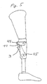
- the swing phase control device 1 When used in an artificial knee joint, which is shown in Fig. 5, the swing phase control device 1 is connected to a connected to the free end 11a of the piston rod 11 fastening member 44 with the prosthetic upper leg part.
- the cylinder 3 is connected in its bottom region by means formed therein recesses 45 with the prosthesis base.
- the operation of the swing phase control apparatus will be described below.
- the piston 12 When the artificial knee joint is extended (extension), the piston 12 is in its retracted upper, the cover part 4 adjacent position.
- the first chamber 8 has its minimum size. This situation is shown in Figs. 1, 3 and 4, respectively.
- the second chamber 17 has its maximum size.
- the knee When the artificial leg of the person using the swing phase control device is flexed, the knee flexes (flexion).
- the piston 12 moves from its upper position to the lower position and ambient air flows through the check valve 9 in the increasing first chamber 8 after.
- the compression spring 30 and the diameter of the throttle 32 are dimensioned so that during normal operation, the pressure in the second chamber 17, the control element 27 can not yet press into a position closing the throttle 32. Therefore, the throttle 32 is free and the piston 12 going down displaces the air present in the second chamber 17 through the bores 18, 50 and 19 to the outside.
- the piston 12 moves quickly to the lower position.
- a high pressure since the air through the throttle 32 is not fast enough from the second chamber 17 via the bore 18 and the throttle 32 can flow to the outlet hole 19. If the bending movement persists long enough, the pressure in the second chamber 17 rises so high that the pressure acting on the control element 27 sufficient to move the control member 27 against the action of the compression spring 30 in a throttle 32 something occlusive position.
- the pressure in the second chamber 17 increases even faster and the control element 27 closes the throttle 32 even faster, so that it is finally completely closed. Then the second chamber acts as an air spring, because the air is only compressed, and can no longer flow.
- the air spring formed by the second chamber 17 causes the submerged movement of the piston 12 is reversed in the cylinder 3 and the piston 12 is pushed out of the cylinder 3 again. Since the upward movement of the piston 12 means an extension of the knee joint, so the stretching movement of the knee joint is actively supported by reversing the movement of the piston 12 which is caused by the air spring in the second chamber 17.
- the person wearing the prosthesis again moves quickly and stretches the knee joint, it moves the piston 12 quickly to the upper position.
- a high pressure since the air through the transverse bore 36 can not drain fast enough over the transverse bore 36 and the bore 35 into the second chamber 17.
- the pressure in the first chamber 8 rises so high that the pressure acting on the second control element 60 sufficient to the second control element 60 against the action of the second compression spring 61 in a transverse bore 36 something occlusive position to move.
- the pressure in the first chamber 8 increases even faster and the second control element 60 closes the transverse bore 36 even faster, so that it is finally completely closed. Then the first chamber acts as an air spring.
- the air spring formed by the first chamber 8 causes the sliding out movement of the piston 12 is reversed from the cylinder 3 and the piston 12 is immersed in the cylinder 3 again. Since the downward movement of the piston 12 means a flexion of the knee joint, therefore, the bending movement of the knee joint is also actively supported by reversing the movement of the piston 12 caused by the air spring in the first chamber 8.
- the first chamber 8 and the second chamber 17 are connected to the ambient air via the inlet opening 7 and the outlet hole 19, respectively. It is therefore an open system in which air is used as the medium. But it can also be a closed system be provided, in which the swing phase control is surrounded by a hermetically sealed outer housing. In the case of such an alternative embodiment, another gas or liquid may also be used as the moving medium. With such an embodiment, the characteristic of the swing phase control can be influenced. However, the use of a liquid does not have the rebounding property previously described due to the low compressibility.
- throttle device 36, 63, 60, 61 provided in the piston 12 and the piston rod 11 so that it serves as a throttle device for a fluid flowing from the second chamber 17 into the first chamber 8, and to provide the other throttle device 18, 19, 32, 30, 27 in the first chamber 8 between the first chamber and the outside of the cylinder 3 so as to serve as throttle means for a fluid flowing from the first chamber 8 to the outside.
- the inlet opening 7 with check valve 9 is arranged in this case in the second chamber 17.
- FIG. 6 arrows schematically show the flow paths of the fluid during a flexion movement of the artificial knee joint.
- the piston 12 moves downwardly compressing the fluid in the second chamber 17.
- the check valve 9 "locks at the second chamber, so that there is no passage for the fluid from the second chamber 17 forms to the outside of the cylinder 3. Consequently, the fluid flows from the second chamber 17 via the throttle 36 'to the outside of the cylinder 3.
- the throttle 36 ' is provided as in the first embodiment with a control 27' which closes the throttle 36 'at a high pressure in the second chamber 17.
- the piston 12 moves upward and the fluid in the first chamber 8 is compressed. Fluid flows from the outside of the cylinder 3 into the second chamber 17 through the check valve 9 "on the second chamber 17, so that no negative pressure is created in the latter
- the check valve 9 'on the first chamber 8 prevents a simple outflow of the fluid from the first chamber 8, so that it flows to the outside of the cylinder via the throttle 32 'from the first chamber 8.
- the throttle 32' on the first chamber 8 is provided, like the throttle 36 ', with a control element 60' which feeds the throttle 32 ' a occurring high pressure in the first chamber 8 closes.
Landscapes
- Health & Medical Sciences (AREA)
- Transplantation (AREA)
- Vascular Medicine (AREA)
- Life Sciences & Earth Sciences (AREA)
- Oral & Maxillofacial Surgery (AREA)
- Engineering & Computer Science (AREA)
- Biomedical Technology (AREA)
- Heart & Thoracic Surgery (AREA)
- Veterinary Medicine (AREA)
- Cardiology (AREA)
- Animal Behavior & Ethology (AREA)
- General Health & Medical Sciences (AREA)
- Public Health (AREA)
- Orthopedic Medicine & Surgery (AREA)
- Prostheses (AREA)
- Paper (AREA)
- Vehicle Body Suspensions (AREA)
Description
- Die vorliegende Erfindung bezieht sich auf eine Schwungphasensteuervorrichtung für ein künstliches Kniegelenk mit einer Kolbenzylindereinrichtung.
- Eine solche Kolbenzylindereinrichtung ist z.B. aus der
EP 0 615 430 B1 bekannt. Die dort beschriebene Schwungphasensteuervorrichtung weist eine erste Kammer auf der einen Seite des Kolbens auf und eine zweite Kammer auf der gegenüberliegenden Seite des Kolbens, wobei die beiden Kammern über eine erste Drossel miteinander verbindbar sind. Eine zweite Drossel ist zum Verbinden der zweiten Kammer mit einem Fluidreservoir vorgesehen, wobei eine Einrichtung so ausgebildet ist, dass sie bei Erreichen bzw. Überschreiten eines vorbestimmten Drucks in der zweiten Kammer die zweite Drossel schließt. - Mit dieser Schwungphasensteuerung wird erreicht, dass das Eintauchen des Kolbens der Kolbenzylindereinrichtung und damit das Beugen des künstlichen Kniegelenks durch die zweite Drossel gesteuert werden kann und die Drosselung abhängig von der Eintauchgeschwindigkeit des Kolbens erfolgt. Damit können unterschiedliche Steuerungen für das Beugen des Kniegelenks realisiert werden und somit wird ein natürlicherer Bewegungsablauf ermöglicht.
- Wenn das Kniegelenk wieder gestreckt werden soll, muss die Person, die das künstliche Kniegelenk benutzt, den Unterschenkel wieder nach vorne schwingen und in die Streckung mit dem Oberschenkel bringen. Hierbei tritt bei der bekannten Schwungphasensteuerung eine vorbestimmte Drosselwirkung auf, bei der die Drosselung über die erste Drossel erfolgt und nicht von der Streckgeschwindigkeit des künstlichen Kniegelenks abhängt.
- Da bei einem natürlichen Bewegungsablauf jedoch auch der Streckvorgang abhängig von der Schrittgeschwindigkeit erfolgt, führt eine solche Drosselung zu einem unnatürlichen Bewegungsablauf. Zwar ist die erste Drossel einstellbar und kann damit an den jeweiligen Laufstil angepasst werden, jedoch weist sie keine dynamische Anpassung an unterschiedliche Bewegungsabläufe der Person auf. Die erste Drossel wirkt also nur optimal entweder für langsame oder für schnelle Bewegungen.
- Es ist Aufgabe der Erfindung, eine Schwungphasensteuerung der eingangs beschriebenen Art zu schaffen, die einen natürlichen Bewegungsablauf ermöglicht und die insbesondere auch für unterschiedlich schnelle Streckbewegungen des künstlichen Kniegelenks geeignet ist.
- Die Aufgabe wird gelöst durch eine Schwungphasensteuerung gemäß Anspruch 1. Weiterbildungen der Erfindung sind in den Unteransprüchen gekennzeichnet.
- Die erfindungsgemäße Schwungphasensteuerung weist den besonderen Vorteil auf, dass sie auch für die Streckbewegung eine Drosselung bereitstellt, die abhängig von der Bewegungsgeschwindigkeit ist und getrennt von der Drosselung der Beugebewegung einstellbar ist. Es wird somit ein Bewegungsablauf ermöglicht, der natürlicher wirkt. Wenn eine schnelle Streckbewegung erfolgt, verkleinert der sich aus dem Zylinder bewegende Kolben sehr schnell das Volumen der ersten Kammer und komprimiert das darin enthaltene Fluid. Überschreitet der Druck einen vorbestimmten Wert, wird die erste Drossel geschlossen und es tritt eine Dämpfung durch das komprimierte Fluid auf.
- Mit der erfindungsgemäßen Schwungphasensteuerung ist folglich ein natürliches und schwungvolles Gehen mit der Prothese möglich.
- Weitere Merkmale und Zweckmäßigkeiten der Erfindung ergeben sich aus der Beschreibung von Ausführungsbeispielen anhand der beigefügten Zeichnungen. Von den Figuren zeigen:
- Fig. 1
- eine Seitenansicht einer Schwungphasensteuereinrichtung einer Ausführungsform der vorliegenden Erfindung;
- Fig. 2
- eine Draufsicht auf die Schwungphasensteuereinrichtung aus Fig. 1;
- Fig. 3
- einen Schnitt entlang der Linie A-A in Fig. 2;
- Fig. 4
- einen Schnitt entlang der Linie B-B in Fig. 1;
- Fig. 5
- eine Darstellung, die die Verwendung der Schwungphasensteuereinrichtung in einem künstlichen Knie einer Beinprothese zeigt;
- Fig. 6
- eine schematische Darstellung einer Schwungphasensteuereinrichtung gemäß einer weiteren Ausführungsform der vorliegenden Erfindung bei einer Flexionsbewegung;
- Fig. 7
- eine schematische Darstellung der in Fig. 6 gezeigten Schwungphasensteuereinrichtung bei einer Extensionsbewegung.
- Im Folgenden wird mit Bezug auf die Fig. 1 bis 4 eine erste Ausführungsform der vorliegenden Erfindung beschrieben.
- Die Schwungphasensteuervorrichtung 1 weist eine Zylinderkolbeneinrichtung 2 mit einem Zylinder 3 und einem Kolben 12 auf. Der Zylinder 3 umfasst einen rohrförmigen Abschnitt 5 mit einem Deckelteil 4 an seinem einen Ende und einem Bodenteil 6 an dem gegenüberliegenden Ende.
- Das Deckelteil 4 weist eine Einlassöffnung 7 auf, die eine Verbindung zwischen der Umgebungsluft und einer in dem Zylinder 3 gebildeten eingangsseitigen ersten Kammer 8 ermöglicht. Die Einlassöffnung 7 ist mit einem Rückschlagventil 9 versehen, das sich zu der ersten Kammer 8 hin öffnet und das beispielsweise als Flatterventil ausgebildet sein kann. Konzentrisch zu dem Zylinder 3 ist eine Bohrung 10 in einer Buchse in dem Deckelteil 4 vorgesehen. In der Bohrung 10 befindet sich ein Gleitlager für eine Kolbenstange 11, die mit dem Kolben 12 der Kolbenzylindereinrichtung 2 verbunden ist. Auf der Außenseite der Einlassöffnung 7 ist ein Filter 13 zum Schutz gegen das Eindringen unerwünschter Bestandteile aus der Außenluft und zum Dämpfen von Geräuschen durch das Hindurchströmen von Luft vorgesehen. Zum Abdichten des Raumes zwischen der konzentrischen Bohrung 10 und der Kolbenstange 11 ist eine Ringdichtung 14 vorgesehen.
- Das Deckelteil 4 ist mit dem rohrförmigen Abschnitt 5 verbunden und die Verbindung zwischen dem rohrförmigen Abschnitt 5 und dem Deckelteil 4 ist beispielsweise durch eine Ringdichtung 15 abgedichtet. Das Bodenteil 6 verschließt den rohrförmigen Abschnitt 5 an seinem dem Deckelteil 4 entgegengesetzten Ende und ist einstückig mit dem rohrförmigen Abschnitt 5 ausgebildet. Das Bodenteil 6 kann auch separat ausgebildet sein und mit dem rohrförmigen Abschnitt 5 verschraubt oder anderweitig verbunden sein.
- Auf der der ersten Kammer 8 abgewandten Seite des Kolbens 12 ist eine zweite Kammer 17 in dem rohrförmigen Abschnitt 5 gebildet. Auf der dem Kolben 12 entgegengesetzten Seite ist die zweite Kammer 17 von dem Bodenteil 6 begrenzt.
- In dem Bodenteil 6 ist konzentrisch eine in die zweite Kammer 17 mündende Bohrung 18 vorgesehen. Das Bodenteil 6 weist eine radiale Bohrung 50 auf, die die Außenseite des Zylinders 3, mit der Bohrung 18 verbindet und mit einem Verschlusselement 51 versehen ist. Die Bohrung 50 zu der entgegengesetzten Außenseite des Zylinders 3 fortsetzend ist eine radiale Auslassbohrung 19 vorgesehen, die die Außenseite des Zylinders 3 und damit die Umgebungsluft mit der Bohrung 18 verbindet. Der der Außenseite zugewandte Abschnitt 19a der Auslassbohrung 19 ist mit einem Filter 20 zum Verhindern des Eintretens von Staub aus der Umgebungsluft und zum Dämpfen von Geräuschen durch das Hindurchströmen von Luft durch die Auslassbohrung 19 versehen. Die radiale Auslassbohrung 19 weist in dem an den Abschnitt 19a in Richtung der Bohrung 18 angrenzenden Abschnitt 19b einen verjüngten Querschnitt auf und in dem direkt an die Bohrung 50 angrenzenden Abschnitt 19c wieder einen größeren Querschnitt, der etwas kleiner ist als der Querschnitt der Bohrung 50.
- Der Durchgang von der Bohrung 18 zu dem Abschnitt 19c ist teilweise von dem Verschlusselement 51 verschlossen, so dass eine Drossel 32 gebildet ist, die ein Ausströmen der Luft aus der zweiten Kammer 17 über die Bohrungen 18, 50 und 19 drosselt. Das Verschlusselement 51 ist derart ausgebildet, dass es den der Bohrung 19 abgewandten Bereich der Bohrung 50 verschließt und mit einem hohlzylinderförmigen Fortsatz 51a in den Durchgang von der Bohrung 18 zu dem Abschnitt 19c ragt.
- In dem hohlzylindrischen Innenraum des Verschlusselements 51 ist ein Steuerelement 27 gehalten, das in dem Verschlusselement 51 koaxial verschiebbar ist. Das Steuerelement 27 ist becherförmig ausgebildet und die Bodenfläche 27a des Bechers bildet eine Seitenwand eines Raums 51c in dem hohlzylindrischen Innenraum des Verschlusselements 51. Dieser Raum 51c steht über eine seitliche Bohrung 51b in dem hohlzylindrischen Fortsatz 51a mit der Bohrung 18 in Kontakt. In einer ersten Endstellung verschließt dieses Steuerelement 27 die Drossel 32 vollständig und in Richtung einer zweiten Endstellung gibt es die Drossel 32 sukzessiv frei. Dieses Steuerelement 27 wird von einer Druckfeder 30, die in den Innenraum des becherförmigen Steuerelements 27 eingreift, in die zweite Endstellung gegen einen Anschlag 25 vorgespannt, der in den Raum 51c ragt. Die Position des Anschlags 25 kann über eine von außen zugängliche Einstellschraube 23 eingestellt werden.
- Wenn von der zweiten Kammer 17 Luft durch die Bohrung 18 in die Bohrung 50 strömt, drückt diese auf die der Druckfeder 30 abgewandten Seite gegen das Steuerelement 27 und bewegt dieses bei Überschreiten der Federkraft in Richtung der die Drossel 32 verschließenden Stellung.
- Der Kolben 12 weist ferner eine konzentrische Bohrung 35 auf, die in die zweite Kammer 17 mündet. An einer der zweiten Kammer 17 abgewandten Seite steht die konzentrische Bohrung 35 über eine Querbohrung 36 mit der ersten Kammer in Verbindung. Die konzentrische Bohrung 35 weist ein sich zur zweiten Kammer hin öffnendes Rückschlagventil 37 auf, das wiederum beispielsweise als Flatterventil ausgebildet sein kann. Der Kolben 12 weist eine Ringdichtung 39 auf, die an den rohrförmigen Abschnitt 5 anliegt. Die konzentrische Bohrung 35 des Kolbens 12 setzt sich in der mit dem Kolben 12 an der dem Deckelteil 4 zugewandten Seite verbundenen Kolbenstange 11 fort. Die Kolbenstange 11 ist also in einem an die konzentrische Bohrung 35 anschließenden Abschnitt hohl mit einem zylindrischen Querschnitt ausgebildet.
- In der Kolbenstange 11 ist ein koaxial zu dieser angeordnetes zweites Steuerelement 60 angeordnet. Das zweite Steuerelement 60 weist einen Außendurchmesser auf, der derart dem Innendurchmesser der hohlen Kolbenstange 11 entsprechend gewählt ist, dass das zweite Steuerelement 60 den Querschnitt der Kolbenstange 11 ausfüllt und in dieser entlang der Stangenachse verschiebbar ist. Das zweite Steuerelement 60 ist in der Kolbenstange 11 derart angeordnet, dass es in einer ersten Endstellung die Querbohrung 36 vollständig verschließt, die eine Drossel für Luft bildet, die von der ersten Kammer 8 in Richtung der zweiten Kammer 17 strömt, und bei Bewegung in Richtung einer zweiten Endstellung die Querbohrung 36 sukzessiv freigibt.
- Auf der dem Kolben 12 zugewandten Seite des zweiten Steuerelements 60 ist in der Kolbenstange 11 eine zweite Druckfeder 61 vorgesehen, die das zweite Steuerelement 60 in Richtung der zweiten Endstellung gegen einen in der Kolbenstange 11 vorgesehenen Anschlag 62 vorspannt.
- In der Kolbenstange 11 ist auf der dem Kolben 12 abgewandten Seite des zweiten Steuerelements 60 eine zweite Querbohrung 63 vorgesehen, die den Innenraum der hohlen Kolbenstange 11 mit der ersten Kammer 8 verbindet. In Richtung des freien Endes 11a der Kolbenstange 11 ist der Innenraum der hohlen Kolbenstange 11 durch ein zweites Verschlusselement 64 begrenzt. Über die zweite Querbohrung 63 wirkt der Druck in der ersten Kammer 8 auf die der zweiten Druckfeder 61 abgewandte Oberseite 60a des zweiten Steuerelements 60. Über eine vom freien Ende 11a zugängliche Schraube kann das zweite Verschlusselement 64 in seiner Position in Richtung der Kolbenstangenachse verstellt werden, sodass mit dem zweiten Steuerelement 60 über den Anschlag 62 die Querbohrung 36 entgegen dem Druck der zweiten Druckfeder 61 teilweise vorverschlossen werden kann. Mit dieser Anordnung ist eine einstellbare Drossel ausgebildet, deren Querschnitt abhängig von dem Druck in der ersten Kammer und damit von der Ausfahrgeschwindigkeit des Kolbens aus dem Zylinder verjüngt wird.
- Bei der Benutzung in einem künstlichen Kniegelenk, die in Fig. 5 dargestellt ist, wird die Schwungphasensteuervorrichtung 1 mit einem mit dem freien Ende 11a der Kolbenstange 11 verbundenen Befestigungsteil 44 mit dem Prothesenoberschenkelteil verbunden. Der Zylinder 3 wird in seinem Bodenbereich durch darin ausgebildete Ausnehmungen 45 mit dem Prothesenunterteil verbunden.
- Im Folgenden wird der Betrieb der Schwungphasensteuerungsvorrichtung beschrieben. Wenn das künstliche Kniegelenk gestreckt ist (Extension), befindet sich der Kolben 12 in seiner zurückgezogenen oberen, dem Deckelteil 4 benachbarten Stellung. Die erste Kammer 8 hat ihre minimale Größe. Diese Situation ist in den Fig. 1, 3 und 4 jeweils dargestellt. Die zweite Kammer 17 hat ihre maximale Größe. Wenn das künstliche Bein der Person, die die Schwungphasensteuervorrichtung verwendet, gebeugt wird, knickt das Kniegelenk ein (Flexion). Der Kolben 12 bewegt sich von seiner oberen Stellung in die untere Stellung und Umgebungsluft strömt durch das Rückschlagventil 9 in die sich vergrößernde erste Kammer 8 nach. Die Druckfeder 30 und der Durchmesser der Drossel 32 sind so bemessen, dass bei normaler Betätigung der Druck in der zweiten Kammer 17 das Steuerelement 27 noch nicht in eine die Drossel 32 verschließende Stellung drücken kann. Daher ist die Drossel 32 frei und der nach unten gehende Kolben 12 verdrängt die in der zweiten Kammer 17 vorhandene Luft durch die Bohrungen 18, 50 und 19 nach außen.
- Wenn sich dagegen die die Prothese tragende Person schnell bewegt und dabei das Kniegelenk beugt, bewegt sich der Kolben 12 schnell in die untere Position. Dabei baut sich in der zweiten Kammer 17 schnell ein hoher Druck auf, da die Luft durch die Drossel 32 nicht schnell genug von der zweiten Kammer 17 über die Bohrung 18 und die Drossel 32 zu der Auslassbohrung 19 abfließen kann. Falls die Beugebewegung lange genug anhält, steigt der Druck in der zweiten Kammer 17 so hoch an, dass der auf das Steuerelement 27 wirkende Druck ausreicht, um das Steuerelement 27 gegen die Wirkung der Druckfeder 30 in eine die Drossel 32 etwas verschließende Stellung zu bewegen. Durch das Verschließen der Drossel 32 steigt der Druck in der zweiten Kammer 17 noch rascher an und das Steuerelement 27 verschließt die Drossel 32 noch schneller, sodass sie schließlich ganz verschlossen ist. Dann wirkt die zweite Kammer als Luftfeder, da die Luft nur noch komprimiert wird, und nicht mehr abfließen kann.
- Die durch die zweite Kammer 17 gebildete Luftfeder bewirkt, dass die eintauchende Bewegung des Kolbens 12 in dem Zylinder 3 umgekehrt wird und der Kolben 12 wieder aus dem Zylinder 3 herausgeschoben wird. Da die Aufwärtsbewegung des Kolbens 12 eine Streckung des Kniegelenks bedeutet, wird also die Streckbewegung des Kniegelenks durch das Umkehren der Bewegung des Kolbens 12 das durch die Luftfeder in der zweiten Kammer 17 verursacht wird, aktiv unterstützt.
- Bei der Streckbewegung des Kniegelenks, wenn der Kolben 12 wieder aus dem Zylinder 3 herausgeschoben wird, strömt Luft aus der ersten Kammer 8 durch die Querbohrung 36, die Bohrung 35 und das in dieser Richtung durchlässige Rückschlagventil 37 in die sich vergrößernde zweite Kammer 17. Die zweite Druckfeder 61 und der Durchmesser der Querbohrung 36 sind so bemessen, dass bei normaler Betätigung der Druck in der ersten Kammer 8 das zweite Steuerelement 60 noch nicht in eine die Querbohrung 36 verschließende Stellung drücken kann. Daher ist die Querbohrung 36 frei und der nach oben gehende Kolben 12 verdrängt die in der ersten Kammer 8 vorhandene Luft in die zweite Kammer 17.
- Wenn sich dagegen die die Prothese tragende Person wiederum schnell bewegt und dabei das Kniegelenk streckt, bewegt sich der Kolben 12 schnell in die obere Position. Dabei baut sich in der ersten Kammer 8 schnell ein hoher Druck auf, da die Luft durch die Querbohrung 36 nicht schnell genug über die Querbohrung 36 und die Bohrung 35 in die zweite Kammer 17 abfließen kann. Falls die Streckbewegung lange genug anhält, steigt der Druck in der ersten Kammer 8 so hoch an, dass der auf das zweite Steuerelement 60 wirkende Druck ausreicht, um das zweite Steuerelement 60 gegen die Wirkung der zweiten Druckfeder 61 in eine die Querbohrung 36 etwas verschließende Stellung zu bewegen. Durch das Verschließen der Querbohrung 36 steigt der Druck in der ersten Kammer 8 noch rascher an und das zweite Steuerelement 60 verschließt die Querbohrung 36 noch schneller, sodass sie schließlich ganz verschlossen ist. Dann wirkt die erste Kammer als Luftfeder.
- Die durch die erste Kammer 8 gebildete Luftfeder bewirkt, dass die herausschiebende Bewegung des Kolbens 12 aus dem Zylinder 3 umgekehrt wird und der Kolben 12 wieder in den Zylinder 3 eingetaucht wird. Da die Abwärtsbewegung des Kolbens 12 eine Beugung des Kniegelenks bedeutet, wird also die Beugebewegung des Kniegelenks durch das Umkehren der Bewegung des Kolbens 12, das durch die Luftfeder in der ersten Kammer 8 verursacht wird, ebenfalls aktiv unterstützt.
- Also werden die Beuge- und die Streckbewegung des Kniegelenks abhängig von der Bewegungsgeschwindigkeit aktiv unterstützt, sodass sich die Person viel schneller und sicherer bewegen kann. Die Zeitpunkte der jeweiligen durch die Luftfedern bedingten Umkehrbewegungen können durch Einstellen der jeweiligen Drosselungen durch Verstellen der Anschläge 25, 62 an die individuellen Gegebenheiten angepasst werden.
- Bei der oben beschriebenen Ausführungsform sind die erste Kammer 8 und die zweite Kammer 17 über die Einlassöffnung 7 bzw. die Auslassbohrung 19 mit der Umgebungsluft verbunden. Es handelt sich also um ein offenes System, bei dem als Medium Luft verwendet wird. Es kann aber auch ein geschlossenes System vorgesehen sein, bei dem die Schwungphasensteuerung von einem hermetisch abgeschlossenen Außengehäuse umgeben ist. Im Fall einer solchen alternativen Ausführungsform kann auch ein anderes Gas oder eine Flüssigkeit als bewegtes Medium verwendet werden. Mit einer solchen Ausführungsform kann die Kennlinie der Schwungphasensteuerung beeinflusst werden. Die Verwendung einer Flüssigkeit weist aber aufgrund der geringen Kompressibilität nicht die rückfedernde Eigenschaft auf, die zuvor beschrieben wurde.
- Es ist in einer weiteren Ausführungsform ebenfalls möglich, die in dem Kolben 12 und der Kolbenstange 11 vorgesehene Drosseleinrichtung 36, 63, 60, 61 umzudrehen, sodass sie als Drosseleinrichtung für ein aus der zweiten Kammer 17 in die erste Kammer 8 strömendes Fluid dient, und die andere Drosseleinrichtung 18, 19, 32, 30, 27 in der ersten Kammer 8 zwischen der ersten Kammer und der Außenseite des Zylinders 3 vorzusehen, sodass sie als Drosseleinrichtung für ein von der ersten Kammer 8 zu der Außenseite strömendes Fluid dient. Die Einlassöffnung 7 mit Rückschlagventil 9 ist in diesem Fall in der zweiten Kammer 17 angeordnet.
- In einer weiteren Ausführungsform ,die in den Fig. 6 und 7 gezeigt ist, ist keine der Drosseln in dem Kolben 12 vorgesehen, sondern beide Drosseln 32', 36' sind jeweils in einem Durchgang zur Umgebungsluft ausgebildet. In jeder der Kammern 8, 17 ist ein Rückschlagventil 9', 9" vorgesehen, das die jeweilige Kammer 8, 17 mit der Außenseite des Zylinders 3 verbindet und in Richtung der Kammer 8, 17 öffnet.
- In der Fig. 6 sind mit Pfeilen schematisch die Strömungswege des Fluids bei einer Flexionsbewegung des künstlichen Kniegelenks dargestellt. Bei der Flexionsbewegung bewegt sich, wie bei der zuvor beschriebenen Ausführungsform, der Kolben 12 nach unten und komprimiert das Fluid in der zweiten Kammer 17. Dabei sperrt das Rückschlagventil 9" an der zweiten Kammer, sodass es für das Fluid keinen Durchgang von der zweiten Kammer 17 zu der Außenseite des Zylinders 3 bildet. Folglich fließt das Fluid von der zweiten Kammer 17 über die Drossel 36' zu der Außenseite des Zylinders 3. Durch das geöffnete Rückschlagventil 9' an der ersten Kammer 8 strömt das Fluid von der Außenseite des Zylinders 3 in die erste Kammer 8. Die Drossel 36' ist wie bei der ersten Ausführungsform mit einem Steuerelement 27' versehen, das die Drossel 36' bei einem hohen Druck in der zweiten Kammer 17 verschließt.
- Bei der in Fig. 7 dargestellten Extensionsbewegung bewegt sich der Kolben 12 nach oben und das Fluid in der ersten Kammer 8 wird komprimiert. Durch das Rückschlagventil 9" an der zweiten Kammer 17 strömt Fluid von der Außenseite des Zylinders 3 in die zweite Kammer 17, sodass in dieser kein Unterdruck entsteht. Das Rückschlagventil 9' an der ersten Kammer 8 verhindert ein einfaches Ausströmen des Fluids aus der ersten Kammer 8, sodass dieses über die Drossel 32' von der ersten Kammer 8 zu der Außenseite des Zylinders strömt. Die Drossel 32' an der ersten Kammer 8 ist so wie die Drossel 36' mit einem Steuerelement 60' versehen, das die Drossel 32' bei einem auftretenden hohen Druck in der ersten Kammer 8 verschließt.
- Als weitere Alternative ist denkbar, beide Drosseln in dem Kolben 12 oder dem Kolben 12 und der Kolbenstange 11 anzuordnen und die Drosseln jeweils in Reihe mit Rückschlagventilen angeordnet in zwei Kanälen anzuordnen. Mit einer solchen Ausführung ist auch ein geschlossenes System, das ein anderes Fluid als die Umgebungsluft verwendet zu realisieren.
Claims (11)
- Schwungphasensteuervorrichtung für ein künstliches Kniegelenk mit einer Kolbenzylindereinrichtung (2) mit einer ersten Kammer (8) auf der einen Seite des Kolbens (12) und einer zweiten Kammer (17) auf der gegenüberliegenden Seite des Kolbens (12),
und mit einer ersten Drossel (36), die das Austreten eines Fluids aus der ersten Kammer (8) drosselt, und einer ersten Einrichtung (63, 60, 61), die so ausgebildet ist, dass sie bei Erreichen bzw. Überschreiten eines vorbestimmten Drucks in der ersten Kammer (8) die erste Drossel (36) schließt,
und mit einer zweiten Drossel (32), die das Austreten des Fluids aus der zweiten Kammer (17) drosselt, und einer zweiten Einrichtung (27, 30, 51b), die so ausgebildet ist, dass sie bei Erreichen bzw. Überschreiten eines vorbestimmten Drucks in der zweiten Kammer (17) die zweite Drossel (32) schließt. - Schwungphasensteuervorrichtung nach Anspruch 1, bei der die erste Drossel (36) in dem Kolben (12, 11) angeordnet ist.
- Schwungphasensteuervorrichtung nach Anspruch 1 oder 2, bei der die erste Kammer (8) und die zweite Kammer (17) über die erste Drossel (36) verbindbar sind.
- Schwungphasensteuervorrichtung nach einem der Ansprüche 1 bis 3, bei der die erste Kammer (8) mit einem Fluidreservoir verbindbar ist.
- Schwungphasensteuervorrichtung nach einem der Ansprüche 1 bis 4, bei der die zweite Drossel (32) auf der dem Kolben (12) abgewandten Ausgangsseite der zweiten Kammer angeordnet ist.
- Schwungphasensteuervorrichtung nach einem der Ansprüche 1 bis 5, bei der die zweite Kammer (17) über die zweite Drossel (32) mit einem Fluidreservoir verbindbar ist.
- Schwungphasensteuervorrichtung nach einem der Ansprüche 1 bis 6, bei der das Fluid Luft ist.
- Schwungphasensteuervorrichtung nach Anspruch 7, bei der das Fluidreservoir aus der Umgebungsluft gebildet ist.
- Schwungphasensteuervorrichtung nach einem der Ansprüche 1 bis 8, bei der das Fluid ein Hydraulikmedium oder ein Pneumatikmedium ist und das Fluidreservoir mit der Umgebung in Druckausgleich steht.
- Schwungphasensteuervorrichtung nach einem der Ansprüche 1 bis 9, bei der die erste Einrichtung (60) und/oder die zweite Einrichtung (27) als ein Steuerkolben (60, 27) ausgebildet sind, der entlang eines Weges hin und her bewegbar ist.
- Schwungphasensteuervorrichtung nach einem der Ansprüche 1 bis 10, bei der die erste Einrichtung (60) und/oder die zweite Einrichtung (27) mit einem eine Rückstellkraft aufbringenden Element (61, 30) versehen sind, das bei Unterschreiten des vorbestimmten Drucks die erste bzw. zweite Drossel (36, 32) wieder freigibt.
Applications Claiming Priority (2)
| Application Number | Priority Date | Filing Date | Title |
|---|---|---|---|
| DE202004008014U DE202004008014U1 (de) | 2004-05-18 | 2004-05-18 | Schwungphasensteuervorrichtung |
| PCT/EP2005/004520 WO2005115279A1 (de) | 2004-05-18 | 2005-04-27 | Schwungphasensteuervorrichtung |
Publications (2)
| Publication Number | Publication Date |
|---|---|
| EP1746956A1 EP1746956A1 (de) | 2007-01-31 |
| EP1746956B1 true EP1746956B1 (de) | 2007-10-03 |
Family
ID=32981496
Family Applications (1)
| Application Number | Title | Priority Date | Filing Date |
|---|---|---|---|
| EP05736345A Expired - Lifetime EP1746956B1 (de) | 2004-05-18 | 2005-04-27 | Schwungphasensteuervorrichtung |
Country Status (5)
| Country | Link |
|---|---|
| US (1) | US20070208431A1 (de) |
| EP (1) | EP1746956B1 (de) |
| AT (1) | ATE374585T1 (de) |
| DE (2) | DE202004008014U1 (de) |
| WO (1) | WO2005115279A1 (de) |
Families Citing this family (13)
| Publication number | Priority date | Publication date | Assignee | Title |
|---|---|---|---|---|
| DE202004008157U1 (de) | 2004-05-19 | 2004-11-04 | medi Bayreuth Weihermüller & Voigtmann GmbH & Co. KG | Prothesengelenk |
| GB0819554D0 (en) * | 2008-10-27 | 2008-12-03 | Orthomobility Ltd | A prosthetic hydraulic joint |
| TWI444176B (zh) | 2012-04-05 | 2014-07-11 | Pro Limb Internat Corp | 免調整之緩衝氣壓缸 |
| TWI477264B (zh) | 2012-11-07 | 2015-03-21 | Pro Limb Internat Corp | 具有緩降功能的膝關節義肢 |
| DE102013016800B4 (de) | 2013-10-10 | 2017-09-14 | Otto Bock Healthcare Gmbh | Dämpfereinrichtung |
| DE102014010254B4 (de) | 2014-07-11 | 2023-06-22 | Ottobock Se & Co. Kgaa | Orthopädietechnische Gelenkeinrichtung |
| EP3034044B1 (de) * | 2014-12-16 | 2017-10-25 | Össur Iceland EHF | Hydraulischer dämpfungszylinder, insbesondere für ein prothesenkniegelenk |
| DE102015100876B4 (de) | 2014-12-16 | 2016-08-11 | medi prosthetics GmbH | Hydraulischer Dämpfungszylinder, insbesondere für ein Prothesenkniegelenk |
| GB201502504D0 (en) | 2015-02-13 | 2015-04-01 | Boender Jonah A B And Boender Jacob Q L | A hydraulic prosthetic joint |
| DE102015116149A1 (de) | 2015-09-24 | 2017-03-30 | Otto Bock Healthcare Gmbh | Orthopädische Gelenkeinrichtung |
| JP6762576B2 (ja) * | 2016-11-10 | 2020-09-30 | 国立大学法人 東京大学 | 膝継手 |
| CN114206272B (zh) | 2019-07-30 | 2025-04-01 | 科里居帕克工业有限公司 | 在过度伸展处具有阻力变化机构的液压假肢膝关节 |
| WO2021102625A1 (zh) * | 2019-11-25 | 2021-06-03 | 苏州西捷克缓冲科技有限公司 | 可调整式旋转阻尼器 |
Family Cites Families (26)
| Publication number | Priority date | Publication date | Assignee | Title |
|---|---|---|---|---|
| US2342578A (en) * | 1941-05-03 | 1944-02-22 | Cons Vultee Aircraft Corp | Damping device for airplane control surfaces |
| US2568051A (en) * | 1947-10-10 | 1951-09-18 | John G Catranis | Artificial leg |
| US2592656A (en) * | 1948-11-19 | 1952-04-15 | John G Catranis | Piston and valve assembly for hydraulic control devices |
| US3007550A (en) * | 1959-11-27 | 1961-11-07 | Gen Motors Corp | Hydraulic shock absorber with rebound cut-off |
| GB1319577A (en) * | 1969-07-08 | 1973-06-06 | Taylor Zwicky Ltd C F | Air operated hydraulic pump |
| DE2721890C3 (de) * | 1977-05-14 | 1980-06-12 | Metallschlauch-Fabrik Pforzheim (Vorm. Hch. Witzenmann) Gmbh, 7530 Pforzheim | Hydraulische Stoßbremse fur Rohrleitungssysteme |
| SE458945B (sv) * | 1985-02-18 | 1989-05-22 | Vaexjoe Protes Ab | Hydraulanordning,speciellt foer benprotes |
| US4702105A (en) * | 1986-03-28 | 1987-10-27 | Paul-Munroe Hydraulics, Inc. | Snubbers and methods and apparatus for the in-place testing thereof |
| US5092902A (en) * | 1990-08-16 | 1992-03-03 | Mauch Laboratories, Inc. | Hydraulic control unit for prosthetic leg |
| CA2057108C (en) * | 1991-12-05 | 1996-12-31 | Kelvin B. James | System for controlling artificial knee joint action in an above knee prosthesis |
| FR2688404B1 (fr) * | 1992-03-11 | 1995-07-13 | Proteor Sa | Dispositif de regulation hydraulique de la marche des amputes femoraux. |
| DE4233247A1 (de) * | 1992-10-02 | 1994-04-07 | Biedermann Motech Gmbh | Schwungphasensteuervorrichtung |
| US5376135A (en) * | 1993-02-25 | 1994-12-27 | Aulie; Alan L. | Adjustable hydraulic damper |
| GB9317634D0 (en) * | 1993-08-25 | 1993-10-13 | Blatchford & Sons Ltd | Antificial limb component |
| DE4338946C1 (de) * | 1993-11-15 | 1995-05-24 | Bock Orthopaed Ind | Prothesengelenk |
| DE9405545U1 (de) * | 1994-03-31 | 1994-06-30 | Biedermann Motech GmbH, 78054 Villingen-Schwenningen | Schwungphasensteuerung für ein künstliches Kniegelenk |
| FR2735018B1 (fr) * | 1995-06-09 | 1997-07-11 | Proteval | Piece prothetique pneumatique pour l'articulation du genou |
| US5779735A (en) * | 1996-05-17 | 1998-07-14 | Molino; Joseph L. | Knee unit for above-knee prosthetic leg |
| GB9813904D0 (en) * | 1997-08-15 | 1998-08-26 | Blatchford & Sons Ltd | A lower limb prosthesis |
| US6117177A (en) * | 1999-03-12 | 2000-09-12 | Teh Lin Prosthetic & Orthopaedic Inc. | Artificial knee joint having a swing phase control member |
| JP3570619B2 (ja) * | 1999-11-15 | 2004-09-29 | 株式会社ナブコ | 義足用エアシリンダ装置 |
| DE10047433C1 (de) * | 2000-09-26 | 2002-01-03 | Stabilus Gmbh | Kolben-Zylinderaggregat mit Bremseinrichtung |
| US6911050B2 (en) * | 2002-10-23 | 2005-06-28 | Joseph L. Molino | Prosthetic knee unit |
| US7374028B2 (en) * | 2003-07-08 | 2008-05-20 | Fox Factory, Inc. | Damper with pressure-sensitive compression damping |
| DE20313999U1 (de) * | 2003-09-09 | 2003-11-20 | Chen Chien Chuan | Multifunktionales künstliches Kniegelenk, das zum schnellen und langsamen Gehen auf Wegen mit Steigung/Gefälle geeignet ist |
| JP4311752B2 (ja) * | 2004-03-29 | 2009-08-12 | ナブテスコ株式会社 | 閉位置を維持可能な切換え弁、ならびにそれを用いたひざトルク装置および義足 |
-
2004
- 2004-05-18 DE DE202004008014U patent/DE202004008014U1/de not_active Expired - Lifetime
-
2005
- 2005-04-27 EP EP05736345A patent/EP1746956B1/de not_active Expired - Lifetime
- 2005-04-27 US US11/569,240 patent/US20070208431A1/en not_active Abandoned
- 2005-04-27 AT AT05736345T patent/ATE374585T1/de active
- 2005-04-27 WO PCT/EP2005/004520 patent/WO2005115279A1/de not_active Ceased
- 2005-04-27 DE DE502005001635T patent/DE502005001635D1/de not_active Expired - Lifetime
Also Published As
| Publication number | Publication date |
|---|---|
| ATE374585T1 (de) | 2007-10-15 |
| US20070208431A1 (en) | 2007-09-06 |
| DE502005001635D1 (de) | 2007-11-15 |
| WO2005115279A1 (de) | 2005-12-08 |
| DE202004008014U1 (de) | 2004-09-09 |
| EP1746956A1 (de) | 2007-01-31 |
Similar Documents
| Publication | Publication Date | Title |
|---|---|---|
| EP0615430B1 (de) | Schwungphasensteuervorrichtung | |
| EP2751364B1 (de) | Dämpfvorrichtung für bewegbare möbelteile | |
| DE3434033C2 (de) | ||
| DE10115162C1 (de) | Druckbegrenzungsventil für Kraftstoff-Einspritzeinrichtungen | |
| DE602004007356T2 (de) | Ventil und verfahren zur bereitstellung eines fluidimpulses | |
| EP3519686B1 (de) | Längenverstellbares pleuel mit steuerungseinrichtung | |
| EP1746956A1 (de) | Schwungphasensteuervorrichtung | |
| DE102017200212A1 (de) | Zweistufenpumpe mit Umschaltventil | |
| EP1851098B9 (de) | Kombinierter federspeicher- und betriebsbremszylinder mit einer beatmungseinrichtung | |
| EP3770445B1 (de) | Anordnung mit einem pneumatischen oder hydraulischen kolbenstangenzylinder | |
| DE2544507C3 (de) | Überlastschutzeinrichtung für Pressen o.dgl | |
| DE19637291C2 (de) | Vorrichtung zur Endlagendämpfung | |
| DE102011013176A1 (de) | Mechanisch entsperrbares Sperrventil mit Druckentlastung | |
| DE202009012627U1 (de) | Kniegelenk | |
| EP0222858B2 (de) | Rohrtrenner | |
| DE10158123B4 (de) | Endlagengedämpfter Druckmittelzylinder | |
| DE2052211A1 (de) | Ventil fur Kompressoranlagen | |
| EP3034044A1 (de) | Hydraulischer dämpfungszylinder, insbesondere für ein prothesenkniegelenk | |
| EP0637711B1 (de) | Ventilvorrichtung für fluide Medien | |
| DE10259314B4 (de) | Elektromagnet | |
| DE19605557A1 (de) | Ventilpatrone | |
| DE102004037316A1 (de) | Handabschaltpistole mit druckentlastetem Handhebel | |
| EP0684383B1 (de) | Flüssigkeitsdosierpumpe | |
| DE2949434A1 (de) | Druckregler | |
| DE1204034B (de) | Steuereinrichtung fuer einen hydraulischen Arbeitskreis |
Legal Events
| Date | Code | Title | Description |
|---|---|---|---|
| PUAI | Public reference made under article 153(3) epc to a published international application that has entered the european phase |
Free format text: ORIGINAL CODE: 0009012 |
|
| 17P | Request for examination filed |
Effective date: 20061206 |
|
| AK | Designated contracting states |
Kind code of ref document: A1 Designated state(s): AT BE BG CH CY CZ DE DK EE ES FI FR GB GR HU IE IS IT LI LT LU MC NL PL PT RO SE SI SK TR |
|
| GRAP | Despatch of communication of intention to grant a patent |
Free format text: ORIGINAL CODE: EPIDOSNIGR1 |
|
| GRAS | Grant fee paid |
Free format text: ORIGINAL CODE: EPIDOSNIGR3 |
|
| DAX | Request for extension of the european patent (deleted) | ||
| GRAA | (expected) grant |
Free format text: ORIGINAL CODE: 0009210 |
|
| AK | Designated contracting states |
Kind code of ref document: B1 Designated state(s): AT BE BG CH CY CZ DE DK EE ES FI FR GB GR HU IE IS IT LI LT LU MC NL PL PT RO SE SI SK TR |
|
| REG | Reference to a national code |
Ref country code: GB Ref legal event code: FG4D Free format text: NOT ENGLISH |
|
| REG | Reference to a national code |
Ref country code: CH Ref legal event code: EP |
|
| REG | Reference to a national code |
Ref country code: IE Ref legal event code: FG4D Free format text: LANGUAGE OF EP DOCUMENT: GERMAN |
|
| REF | Corresponds to: |
Ref document number: 502005001635 Country of ref document: DE Date of ref document: 20071115 Kind code of ref document: P |
|
| REG | Reference to a national code |
Ref country code: CH Ref legal event code: NV Representative=s name: NOVAGRAAF INTERNATIONAL SA |
|
| GBT | Gb: translation of ep patent filed (gb section 77(6)(a)/1977) |
Effective date: 20080113 |
|
| ET | Fr: translation filed | ||
| PG25 | Lapsed in a contracting state [announced via postgrant information from national office to epo] |
Ref country code: SE Free format text: LAPSE BECAUSE OF FAILURE TO SUBMIT A TRANSLATION OF THE DESCRIPTION OR TO PAY THE FEE WITHIN THE PRESCRIBED TIME-LIMIT Effective date: 20080103 Ref country code: ES Free format text: LAPSE BECAUSE OF FAILURE TO SUBMIT A TRANSLATION OF THE DESCRIPTION OR TO PAY THE FEE WITHIN THE PRESCRIBED TIME-LIMIT Effective date: 20080114 |
|
| PG25 | Lapsed in a contracting state [announced via postgrant information from national office to epo] |
Ref country code: BG Free format text: LAPSE BECAUSE OF FAILURE TO SUBMIT A TRANSLATION OF THE DESCRIPTION OR TO PAY THE FEE WITHIN THE PRESCRIBED TIME-LIMIT Effective date: 20080103 Ref country code: LT Free format text: LAPSE BECAUSE OF FAILURE TO SUBMIT A TRANSLATION OF THE DESCRIPTION OR TO PAY THE FEE WITHIN THE PRESCRIBED TIME-LIMIT Effective date: 20071003 Ref country code: PT Free format text: LAPSE BECAUSE OF FAILURE TO SUBMIT A TRANSLATION OF THE DESCRIPTION OR TO PAY THE FEE WITHIN THE PRESCRIBED TIME-LIMIT Effective date: 20080303 Ref country code: PL Free format text: LAPSE BECAUSE OF FAILURE TO SUBMIT A TRANSLATION OF THE DESCRIPTION OR TO PAY THE FEE WITHIN THE PRESCRIBED TIME-LIMIT Effective date: 20071003 Ref country code: IS Free format text: LAPSE BECAUSE OF FAILURE TO SUBMIT A TRANSLATION OF THE DESCRIPTION OR TO PAY THE FEE WITHIN THE PRESCRIBED TIME-LIMIT Effective date: 20080203 |
|
| REG | Reference to a national code |
Ref country code: IE Ref legal event code: FD4D |
|
| PG25 | Lapsed in a contracting state [announced via postgrant information from national office to epo] |
Ref country code: CZ Free format text: LAPSE BECAUSE OF FAILURE TO SUBMIT A TRANSLATION OF THE DESCRIPTION OR TO PAY THE FEE WITHIN THE PRESCRIBED TIME-LIMIT Effective date: 20071003 Ref country code: DK Free format text: LAPSE BECAUSE OF FAILURE TO SUBMIT A TRANSLATION OF THE DESCRIPTION OR TO PAY THE FEE WITHIN THE PRESCRIBED TIME-LIMIT Effective date: 20071003 |
|
| PLBE | No opposition filed within time limit |
Free format text: ORIGINAL CODE: 0009261 |
|
| STAA | Information on the status of an ep patent application or granted ep patent |
Free format text: STATUS: NO OPPOSITION FILED WITHIN TIME LIMIT |
|
| PG25 | Lapsed in a contracting state [announced via postgrant information from national office to epo] |
Ref country code: SK Free format text: LAPSE BECAUSE OF FAILURE TO SUBMIT A TRANSLATION OF THE DESCRIPTION OR TO PAY THE FEE WITHIN THE PRESCRIBED TIME-LIMIT Effective date: 20071003 Ref country code: RO Free format text: LAPSE BECAUSE OF FAILURE TO SUBMIT A TRANSLATION OF THE DESCRIPTION OR TO PAY THE FEE WITHIN THE PRESCRIBED TIME-LIMIT Effective date: 20071003 |
|
| 26N | No opposition filed |
Effective date: 20080704 |
|
| PG25 | Lapsed in a contracting state [announced via postgrant information from national office to epo] |
Ref country code: IE Free format text: LAPSE BECAUSE OF FAILURE TO SUBMIT A TRANSLATION OF THE DESCRIPTION OR TO PAY THE FEE WITHIN THE PRESCRIBED TIME-LIMIT Effective date: 20071003 |
|
| PG25 | Lapsed in a contracting state [announced via postgrant information from national office to epo] |
Ref country code: MC Free format text: LAPSE BECAUSE OF NON-PAYMENT OF DUE FEES Effective date: 20080430 |
|
| PG25 | Lapsed in a contracting state [announced via postgrant information from national office to epo] |
Ref country code: GR Free format text: LAPSE BECAUSE OF FAILURE TO SUBMIT A TRANSLATION OF THE DESCRIPTION OR TO PAY THE FEE WITHIN THE PRESCRIBED TIME-LIMIT Effective date: 20080104 Ref country code: EE Free format text: LAPSE BECAUSE OF FAILURE TO SUBMIT A TRANSLATION OF THE DESCRIPTION OR TO PAY THE FEE WITHIN THE PRESCRIBED TIME-LIMIT Effective date: 20071003 |
|
| PG25 | Lapsed in a contracting state [announced via postgrant information from national office to epo] |
Ref country code: SI Free format text: LAPSE BECAUSE OF FAILURE TO SUBMIT A TRANSLATION OF THE DESCRIPTION OR TO PAY THE FEE WITHIN THE PRESCRIBED TIME-LIMIT Effective date: 20071003 |
|
| PG25 | Lapsed in a contracting state [announced via postgrant information from national office to epo] |
Ref country code: CY Free format text: LAPSE BECAUSE OF FAILURE TO SUBMIT A TRANSLATION OF THE DESCRIPTION OR TO PAY THE FEE WITHIN THE PRESCRIBED TIME-LIMIT Effective date: 20071003 |
|
| PG25 | Lapsed in a contracting state [announced via postgrant information from national office to epo] |
Ref country code: FI Free format text: LAPSE BECAUSE OF FAILURE TO SUBMIT A TRANSLATION OF THE DESCRIPTION OR TO PAY THE FEE WITHIN THE PRESCRIBED TIME-LIMIT Effective date: 20071003 |
|
| PG25 | Lapsed in a contracting state [announced via postgrant information from national office to epo] |
Ref country code: LU Free format text: LAPSE BECAUSE OF NON-PAYMENT OF DUE FEES Effective date: 20080427 Ref country code: HU Free format text: LAPSE BECAUSE OF FAILURE TO SUBMIT A TRANSLATION OF THE DESCRIPTION OR TO PAY THE FEE WITHIN THE PRESCRIBED TIME-LIMIT Effective date: 20080404 |
|
| PG25 | Lapsed in a contracting state [announced via postgrant information from national office to epo] |
Ref country code: TR Free format text: LAPSE BECAUSE OF FAILURE TO SUBMIT A TRANSLATION OF THE DESCRIPTION OR TO PAY THE FEE WITHIN THE PRESCRIBED TIME-LIMIT Effective date: 20071003 |
|
| REG | Reference to a national code |
Ref country code: CH Ref legal event code: PFA Owner name: TEKO AUTOMATION, MENSCH UND TECHNIK GMBH Free format text: TEKO AUTOMATION, MENSCH UND TECHNIK GMBH#HIRSCHBERGSTRASSE 25/1#78054 VS-SCHWENNINGEN (DE) -TRANSFER TO- TEKO AUTOMATION, MENSCH UND TECHNIK GMBH#HIRSCHBERGSTRASSE 25/1#78054 VS-SCHWENNINGEN (DE) |
|
| REG | Reference to a national code |
Ref country code: CH Ref legal event code: PUE Owner name: BIEDERMANN TECHNOLOGIES GMBH & CO.KG Free format text: TEKO AUTOMATION, MENSCH UND TECHNIK GMBH#HIRSCHBERGSTRASSE 25/1#78054 VS-SCHWENNINGEN (DE) -TRANSFER TO- BIEDERMANN TECHNOLOGIES GMBH & CO.KG#JOSEFSTRASSE 5#78166 DONAUESCHINGEN (DE) |
|
| REG | Reference to a national code |
Ref country code: DE Ref legal event code: R082 Ref document number: 502005001635 Country of ref document: DE Representative=s name: PRUEFER & PARTNER GBR, DE |
|
| REG | Reference to a national code |
Ref country code: FR Ref legal event code: TP Owner name: BIEDERMANN TECHNOLOGIES GMBH & CO. KG, DE Effective date: 20120412 |
|
| REG | Reference to a national code |
Ref country code: GB Ref legal event code: 732E Free format text: REGISTERED BETWEEN 20120531 AND 20120606 |
|
| REG | Reference to a national code |
Ref country code: DE Ref legal event code: R081 Ref document number: 502005001635 Country of ref document: DE Owner name: BIEDERMANN TECHNOLOGIES GMBH & CO. KG, DE Free format text: FORMER OWNER: TEKO AUTOMATION, MENSCH UND TECHNIK GMBH, 78054 VILLINGEN-SCHWENNINGEN, DE Effective date: 20120509 Ref country code: DE Ref legal event code: R082 Ref document number: 502005001635 Country of ref document: DE Representative=s name: PRUEFER & PARTNER GBR, DE Effective date: 20120509 Ref country code: DE Ref legal event code: R082 Ref document number: 502005001635 Country of ref document: DE Representative=s name: PRUEFER & PARTNER MBB PATENTANWAELTE RECHTSANW, DE Effective date: 20120509 |
|
| REG | Reference to a national code |
Ref country code: NL Ref legal event code: SD Effective date: 20130131 |
|
| REG | Reference to a national code |
Ref country code: AT Ref legal event code: PC Ref document number: 374585 Country of ref document: AT Kind code of ref document: T Owner name: BIEDERMANN TECHNOLOGIES GMBH & CO. KG, DE Effective date: 20130920 |
|
| REG | Reference to a national code |
Ref country code: FR Ref legal event code: PLFP Year of fee payment: 12 |
|
| REG | Reference to a national code |
Ref country code: FR Ref legal event code: PLFP Year of fee payment: 13 |
|
| PGFP | Annual fee paid to national office [announced via postgrant information from national office to epo] |
Ref country code: NL Payment date: 20170424 Year of fee payment: 13 |
|
| PGFP | Annual fee paid to national office [announced via postgrant information from national office to epo] |
Ref country code: AT Payment date: 20170424 Year of fee payment: 13 Ref country code: IT Payment date: 20170426 Year of fee payment: 13 Ref country code: BE Payment date: 20170424 Year of fee payment: 13 |
|
| REG | Reference to a national code |
Ref country code: NL Ref legal event code: MM Effective date: 20180501 |
|
| REG | Reference to a national code |
Ref country code: AT Ref legal event code: MM01 Ref document number: 374585 Country of ref document: AT Kind code of ref document: T Effective date: 20180427 |
|
| REG | Reference to a national code |
Ref country code: BE Ref legal event code: MM Effective date: 20180430 |
|
| PG25 | Lapsed in a contracting state [announced via postgrant information from national office to epo] |
Ref country code: NL Free format text: LAPSE BECAUSE OF NON-PAYMENT OF DUE FEES Effective date: 20180501 Ref country code: AT Free format text: LAPSE BECAUSE OF NON-PAYMENT OF DUE FEES Effective date: 20180427 |
|
| PG25 | Lapsed in a contracting state [announced via postgrant information from national office to epo] |
Ref country code: BE Free format text: LAPSE BECAUSE OF NON-PAYMENT OF DUE FEES Effective date: 20180430 |
|
| PG25 | Lapsed in a contracting state [announced via postgrant information from national office to epo] |
Ref country code: FR Free format text: LAPSE BECAUSE OF NON-PAYMENT OF DUE FEES Effective date: 20180430 Ref country code: IT Free format text: LAPSE BECAUSE OF NON-PAYMENT OF DUE FEES Effective date: 20180427 |
|
| PGFP | Annual fee paid to national office [announced via postgrant information from national office to epo] |
Ref country code: GB Payment date: 20220425 Year of fee payment: 18 Ref country code: DE Payment date: 20220427 Year of fee payment: 18 |
|
| PGFP | Annual fee paid to national office [announced via postgrant information from national office to epo] |
Ref country code: CH Payment date: 20220425 Year of fee payment: 18 |
|
| REG | Reference to a national code |
Ref country code: DE Ref legal event code: R119 Ref document number: 502005001635 Country of ref document: DE |
|
| REG | Reference to a national code |
Ref country code: CH Ref legal event code: PL |
|
| GBPC | Gb: european patent ceased through non-payment of renewal fee |
Effective date: 20230427 |
|
| PG25 | Lapsed in a contracting state [announced via postgrant information from national office to epo] |
Ref country code: GB Free format text: LAPSE BECAUSE OF NON-PAYMENT OF DUE FEES Effective date: 20230427 |
|
| PG25 | Lapsed in a contracting state [announced via postgrant information from national office to epo] |
Ref country code: LI Free format text: LAPSE BECAUSE OF NON-PAYMENT OF DUE FEES Effective date: 20230430 Ref country code: GB Free format text: LAPSE BECAUSE OF NON-PAYMENT OF DUE FEES Effective date: 20230427 Ref country code: DE Free format text: LAPSE BECAUSE OF NON-PAYMENT OF DUE FEES Effective date: 20231103 Ref country code: CH Free format text: LAPSE BECAUSE OF NON-PAYMENT OF DUE FEES Effective date: 20230430 |