EP1746479A1 - Mechanisch betriebene Flüssigkeitspumpe - Google Patents
Mechanisch betriebene Flüssigkeitspumpe Download PDFInfo
- Publication number
- EP1746479A1 EP1746479A1 EP05015965A EP05015965A EP1746479A1 EP 1746479 A1 EP1746479 A1 EP 1746479A1 EP 05015965 A EP05015965 A EP 05015965A EP 05015965 A EP05015965 A EP 05015965A EP 1746479 A1 EP1746479 A1 EP 1746479A1
- Authority
- EP
- European Patent Office
- Prior art keywords
- housing
- liquid
- pump according
- balloon
- pump
- Prior art date
- Legal status (The legal status is an assumption and is not a legal conclusion. Google has not performed a legal analysis and makes no representation as to the accuracy of the status listed.)
- Ceased
Links
Images


Classifications
-
- A—HUMAN NECESSITIES
- A61—MEDICAL OR VETERINARY SCIENCE; HYGIENE
- A61M—DEVICES FOR INTRODUCING MEDIA INTO, OR ONTO, THE BODY; DEVICES FOR TRANSDUCING BODY MEDIA OR FOR TAKING MEDIA FROM THE BODY; DEVICES FOR PRODUCING OR ENDING SLEEP OR STUPOR
- A61M5/00—Devices for bringing media into the body in a subcutaneous, intra-vascular or intramuscular way; Accessories therefor, e.g. filling or cleaning devices, arm-rests
- A61M5/14—Infusion devices, e.g. infusing by gravity; Blood infusion; Accessories therefor
- A61M5/142—Pressure infusion, e.g. using pumps
- A61M5/14244—Pressure infusion, e.g. using pumps adapted to be carried by the patient, e.g. portable on the body
-
- A—HUMAN NECESSITIES
- A61—MEDICAL OR VETERINARY SCIENCE; HYGIENE
- A61M—DEVICES FOR INTRODUCING MEDIA INTO, OR ONTO, THE BODY; DEVICES FOR TRANSDUCING BODY MEDIA OR FOR TAKING MEDIA FROM THE BODY; DEVICES FOR PRODUCING OR ENDING SLEEP OR STUPOR
- A61M5/00—Devices for bringing media into the body in a subcutaneous, intra-vascular or intramuscular way; Accessories therefor, e.g. filling or cleaning devices, arm-rests
- A61M5/14—Infusion devices, e.g. infusing by gravity; Blood infusion; Accessories therefor
- A61M5/142—Pressure infusion, e.g. using pumps
- A61M5/145—Pressure infusion, e.g. using pumps using pressurised reservoirs, e.g. pressurised by means of pistons
- A61M5/148—Pressure infusion, e.g. using pumps using pressurised reservoirs, e.g. pressurised by means of pistons flexible, e.g. independent bags
- A61M5/152—Pressure infusion, e.g. using pumps using pressurised reservoirs, e.g. pressurised by means of pistons flexible, e.g. independent bags pressurised by contraction of elastic reservoirs
-
- F—MECHANICAL ENGINEERING; LIGHTING; HEATING; WEAPONS; BLASTING
- F04—POSITIVE - DISPLACEMENT MACHINES FOR LIQUIDS; PUMPS FOR LIQUIDS OR ELASTIC FLUIDS
- F04B—POSITIVE-DISPLACEMENT MACHINES FOR LIQUIDS; PUMPS
- F04B13/00—Pumps specially modified to deliver fixed or variable measured quantities
-
- F—MECHANICAL ENGINEERING; LIGHTING; HEATING; WEAPONS; BLASTING
- F04—POSITIVE - DISPLACEMENT MACHINES FOR LIQUIDS; PUMPS FOR LIQUIDS OR ELASTIC FLUIDS
- F04B—POSITIVE-DISPLACEMENT MACHINES FOR LIQUIDS; PUMPS
- F04B43/00—Machines, pumps, or pumping installations having flexible working members
- F04B43/0009—Special features
- F04B43/0054—Special features particularities of the flexible members
- F04B43/0063—Special features particularities of the flexible members bell-shaped flexible members
-
- G—PHYSICS
- G05—CONTROLLING; REGULATING
- G05D—SYSTEMS FOR CONTROLLING OR REGULATING NON-ELECTRIC VARIABLES
- G05D16/00—Control of fluid pressure
- G05D16/04—Control of fluid pressure without auxiliary power
- G05D16/06—Control of fluid pressure without auxiliary power the sensing element being a flexible membrane, yielding to pressure, e.g. diaphragm, bellows, capsule
- G05D16/063—Control of fluid pressure without auxiliary power the sensing element being a flexible membrane, yielding to pressure, e.g. diaphragm, bellows, capsule the sensing element being a membrane
- G05D16/0638—Control of fluid pressure without auxiliary power the sensing element being a flexible membrane, yielding to pressure, e.g. diaphragm, bellows, capsule the sensing element being a membrane characterised by the form of the obturator
- G05D16/0641—Control of fluid pressure without auxiliary power the sensing element being a flexible membrane, yielding to pressure, e.g. diaphragm, bellows, capsule the sensing element being a membrane characterised by the form of the obturator the obturator is a membrane
-
- A—HUMAN NECESSITIES
- A61—MEDICAL OR VETERINARY SCIENCE; HYGIENE
- A61M—DEVICES FOR INTRODUCING MEDIA INTO, OR ONTO, THE BODY; DEVICES FOR TRANSDUCING BODY MEDIA OR FOR TAKING MEDIA FROM THE BODY; DEVICES FOR PRODUCING OR ENDING SLEEP OR STUPOR
- A61M2205/00—General characteristics of the apparatus
- A61M2205/33—Controlling, regulating or measuring
- A61M2205/3331—Pressure; Flow
-
- A—HUMAN NECESSITIES
- A61—MEDICAL OR VETERINARY SCIENCE; HYGIENE
- A61M—DEVICES FOR INTRODUCING MEDIA INTO, OR ONTO, THE BODY; DEVICES FOR TRANSDUCING BODY MEDIA OR FOR TAKING MEDIA FROM THE BODY; DEVICES FOR PRODUCING OR ENDING SLEEP OR STUPOR
- A61M5/00—Devices for bringing media into the body in a subcutaneous, intra-vascular or intramuscular way; Accessories therefor, e.g. filling or cleaning devices, arm-rests
- A61M5/14—Infusion devices, e.g. infusing by gravity; Blood infusion; Accessories therefor
- A61M5/141—Infusion devices, e.g. infusing by gravity; Blood infusion; Accessories therefor with capillaries for restricting fluid flow
-
- A—HUMAN NECESSITIES
- A61—MEDICAL OR VETERINARY SCIENCE; HYGIENE
- A61M—DEVICES FOR INTRODUCING MEDIA INTO, OR ONTO, THE BODY; DEVICES FOR TRANSDUCING BODY MEDIA OR FOR TAKING MEDIA FROM THE BODY; DEVICES FOR PRODUCING OR ENDING SLEEP OR STUPOR
- A61M5/00—Devices for bringing media into the body in a subcutaneous, intra-vascular or intramuscular way; Accessories therefor, e.g. filling or cleaning devices, arm-rests
- A61M5/14—Infusion devices, e.g. infusing by gravity; Blood infusion; Accessories therefor
- A61M5/168—Means for controlling media flow to the body or for metering media to the body, e.g. drip meters, counters ; Monitoring media flow to the body
- A61M5/16877—Adjusting flow; Devices for setting a flow rate
- A61M5/16881—Regulating valves
Definitions
- the invention relates to a mechanically operated liquid pump, in particular for medical or nutritional physiological fluids, as well as liquids in the biological and laboratory field.
- liquid pumps To be associated with the promotion of medical, nutritional or biological fluids or laboratory fluids used the most varied types of liquid pumps.
- electro-energetic, electrochemical, gaseous, mechanical, electromechanical and mechanically-physically operated pumps As a rule, many of these pumps can only be used after a longer start-up period and often offer the user and consumer only insufficient dosing accuracy.
- the known pump systems are quite costly and not very advantageous from an ecological point of view. They are often not portable by the user.
- a mechanically operated liquid pump, in particular for medical or nutritional physiological fluids is known from EP 0 944 405 B1 known.
- This has a housing which is designed as a tube.
- an expandable elastic member for storing and dispensing the liquid is arranged, which is formed as a hose.
- This has openings in the region of its ends.
- the hose is connected in the region of the one opening a conduit for supplying the liquid to the hose.
- In the other opening is connected to the hose another line, which serves to discharge the liquid from the hose.
- This line is led out of the housing.
- the tube end remote from the line is provided with a means for limiting the output from the elastic member liquid volume flow.
- a mechanically operated liquid pump in particular for medical and nutritional physiological fluids known. It has a bag for holding the liquid and a discharge line for the liquid. The bag is placed in a housing of the pump.
- the housing has a first housing part with hinges on both sides for receiving a second housing part and a closing cover for the second housing part. Both housing parts is associated with a device for exerting a compressive force on the bag for dispensing the liquid from the bag.
- This device has an elastic element for acting on a bag side and the second housing part for acting on the opposite side of the bag.
- the bags used in the pump or the pump itself can be used once or used several times.
- the elastic element is designed in the return case so that the liquid is expressed as long from the bag until the elastic member rests against the second housing part for acting on the opposite side of the bag and is emptied in this state, the bag.
- valve In the EP 1 321 156 A1 is a valve, especially for medical and nutritional fluids described.
- This valve allows a largely constant holding of the valve passing liquid flow.
- Part of the valve forms a valve body which has the function of an active control element whose function depends on the pressure acting in a chamber of the valve fluid pressure. Increases the pressure in the liquid chamber, this leads to an adjusting movement of the valve body, which throttles the exit of the liquid from the inlet channel of the valve, while a decrease in the liquid pressure in the chamber causes the valve body performs a movement that the throttling of reduces the liquid emerging from the inlet channel.
- a flow restrictor is inserted in the outlet of the valve.
- a device for dispensing a fluid to an outlet wherein the fluid is in particular a medical Liquid acts.
- This fluid is delivered by an expandable elastic member for storing and dispensing the fluid to a tube that connects to a patient-side cannula.
- the hose is associated with a means for limiting the output by the elastic element liquid volume flow. This lead forms the main line.
- a secondary line which opens behind the limiting device back into the main line.
- the secondary line is provided with a bolus dose device.
- the object of the present invention is to provide a mechanically operated liquid pump, in particular for medical or nutritional physiological fluids, in which all functional parts required for the function of the liquid pump are accommodated in a unit, which is particularly compact, whereby this arrangement of the functional parts should be ensured that a malfunction of the pump is excluded and therefore when using the pump in the field of medicine, this only needs to be connected to the patient.
- all essential for the function of the liquid pump functional parts are thus arranged within the housing of the liquid pump.
- the outlet is thus provided in this case for connection to a device connectable to the patient.
- the operation of the liquid pump is thus very simple. Incorrect operations are excluded, in case of application of the pump in the field of medicine, the patient is only connected.
- the inventive design of the liquid pump with the stored inside the housing functional parts it is possible to make the pump small and compact.
- the functional parts are calibrated.
- the functional parts are thus in their physical behavior to each other matched, so that from the pump, regardless of the pressure state in the expandable elastic element, a substantially constant liquid volume flow is output.
- the housing is at least in an area which the access, the means for substantially keeping constant and / or limiting the output of the elastic element liquid volume flow and the outlet, in particular the housing as a whole, non-destructive disassembled. Accordingly, if the housing as a whole is intact in the area located with respect to the aforementioned functional parts, i. not destroyed, this is for the user of the pump a guarantee that was not tampered with the pump.
- the access and / or the outlet are preferably designed as LuerLock valve or LuerLock connection. These are therefore standardized valves or connections, which allow an uncomplicated feeding or discharging the liquid.
- the expandable elastic member is formed as a balloon which is provided with an opening, wherein the balloon is sealed mounted in a housing mounted in the core core and the core at least one channel for access and exit the liquid in the balloon or from the balloon interspersed.
- It is thus an elastic element provided with a single opening, as opposed to a tube with two openings. As a result, this opening serves both as access for the liquid and as a discharge for the liquid.
- the balloon is preferably in a relatively relaxed state at the core. This is to be understood that the balloon can certainly be present with a certain bias to the core, since the complete emptying of the balloon is desirable.
- the balloon is fastened and sealed exclusively in the area of its end having the opening.
- the balloon can basically be made from any Material may be formed, which has the necessary elasticity for storing and dispensing the liquid. As a preferred material is considered silicone. It is especially intended for a capacity of the balloon of 10 ml to 150 ml.
- the balloon in a first extension direction perpendicular to the longitudinal axis of the core relatively thick wall sections and in a second extension direction perpendicular to the longitudinal axis of the core and perpendicular to the first direction of extension relative having thin wall sections. This means that the balloon deforms more in the region of the thin wall sections, which results in an elongated cross-sectional configuration substantially similar to the shape of an ellipse when the element is stretched.
- the balloon is manufactured in particular by injection molding.
- the means for limiting the output from the elastic element liquid volume flow is designed as a valve, in particular as a pressure control valve.
- the device for largely keeping constant the liquid volume flow output by the elastic element is preferably designed as a flow restrictor, in particular as a glass capillary or meander chip.
- a filter element for the liquid is preferably arranged within the housing, in particular upstream of the device for keeping substantially constant the volume flow of liquid discharged from the elastic element.
- the housing is advantageously designed in several parts. It has, in particular, a middle part, a top part and a bottom part, wherein the designation upper part and lower part has been selected above only to make a linguistic distinction to cause these parts with respect to the middle part. Since the orientation of the pump is arbitrary, the upper part of the lower part and the lower part can represent the upper part.
- the housing is designed in several parts, it is possible to assign the individual parts of the housing and the parting planes of the individual housing parts, for example, the space between the middle part and upper part defined functions:
- the housing expedient one with the upper part and the lower part connectable, in particular insoluble clipped hood, within which the balloon and the core is arranged on.
- the core for the balloon and / or the outlet and / or the filter element and / or the device for limiting the liquid element emanating from the elastic element is / are suitable.
- the device for limiting the volume flow output by the elastic element and / or a bolus device is advantageously mounted.
- the upper part or lower part of the access is preferably stored.
- an upper housing part for covering the upper part and a lower housing part for covering the lower part is provided.
- the individual parts of the housing are preferably made of plastic. This makes it possible to shape the parts almost arbitrarily and produce inexpensive and with low weight. Parts are joined together in particular by laser welding.
- a special function comes with the housing to the middle part.
- this not only serves to accommodate functional parts, but also has the middle part and the flow connections between the functional parts, which are designed in particular as embossed into the central part channels.
- These channels are covered by connecting the middle part with the upper part or lower part, a liquid-tightness of the channels between the middle part and upper part or lower part is achieved in particular by laser welding.
- this or the housing is formed relatively flat. In the area of the balloon this is achieved by the special cross-sectional design of the balloon and the formation of the housing as a hood.
- the remaining region of the housing is formed flat and takes the functional parts arranged there next to each other, on different levels, on the one hand in the region of middle part and upper part, on the other hand in the region of middle part and lower part.
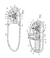
- the mechanically operated liquid pump 1 illustrated in FIG. 1 serves, in particular, for the administration of medicinal or nutritional-physiological fluids, for example the administration of a liquid medicament.
- the pump 1 has a multi-part housing 2, which is formed by a central part 3, cooperating with this upper part 4 and lower part 5, cooperating with the upper part of the upper shell 6 and cooperating with the lower part 5 lower shell 7.
- the middle part 3 is provided on its upper side with a recess 8 which is open to the free edge of the central part 3 and has a semicircular cross-section, and the upper part 4 is provided with a corresponding semicircular recess 9 in the corresponding edge region on its underside.
- the two recesses 8 and 9 form a circular cross-section for receiving a cone-shaped widened end portion 10 of a core 11. This has, except for the end portion 10, a constant outer diameter.
- This cylindrical portion of the core 11 is designated by the reference numeral 12.
- the core 11 passes through in its longitudinal central axis a channel 13 (see FIG.
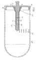
- the core 11 cooperates with an elastic element which is designed as a balloon 16 made of silicone. This is manufactured by injection molding.
- the balloon has, corresponding to the end region 10 of the core 11, a conically widened end region 17 with an opening 17a and one of the outer ones Shape of the portion 12 of the core 11 corresponding portion 18, which opens into the balloon conditionally, closed end portion 19, which faces away from the end portion 17.
- core 11 and balloon 16 are dimensioned so that, as can be seen in Figure 2, the plugged onto the core 11 balloon completely rests against the core 11, thus the end portion 17 of the balloon contacted the end portion 10 of the core and the Section 18 of the balloon 16, the portion 12 of the core 11 contacted, finally, the end portion 19 of the balloon 16 at the front-side free end of the core 11 is applied.
- the dimensions of the balloon 16 with respect to the core 11 are in this case selected so that the balloon 16 with relatively low bias voltage, thus in a relatively relaxed state on the core 11 is applied.
- a clamping ring 20 is provided, which is externally attached to the balloon 16 in the region of its end region 17.
- the thus created structure is inserted with the clamping ring 20 in the recess 8 of the middle part 3, then the upper part 4 connected to the central part 3, whereby the clamping ring 20 and thus the core 11 and the balloon 16 fixed in the recesses 8 and 9 of the middle part 3 and upper part 4 are held.
- the recesses 8 and 9 have a tapering away from the respective free edge of the central part 3 and upper part 4 tapered conical receptacle for the clamping ring 20 in order to ensure a secure fit of the clamping ring 20.
- the middle part 3, the upper part 4 and the lower part 5 serve to receive further functional elements of the pump 1:
- LuerLock valve 21 Connected to the upper part 4 is a LuerLock valve 21, which passes through an opening 22 in the upper part 4 and, as can be seen from the description of FIG. 2 referred to below, has a LuerLock valve housing 23 and a LuerLock valve core 24. Via a channel 25 is the LuerLock valve 21 with a channel 26 in connection, which is formed between the upper part 4 and the central part 3 and which is in communication with the core 11 passing through channel 13.
- the pump is filled with liquid.
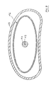
- the balloon 16 expands in that region which is not clamped by the clamping ring 20 and assumes the final shape illustrated in Figure 3 when fully filled.
- the space occupied by the liquid is denoted by the reference numeral 27 there.
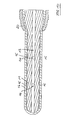
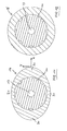
- Figures 2, 3 and 6 to 12 it can be seen that the balloon 16, starting from its voltage applied to the core 11 initial state when filled with liquid its shape both in the longitudinal direction of the core and in its transverse directions changed, d. H. in a first transverse direction and a perpendicular thereto seen second transverse direction.
- the upper part 4 and the lower part 5 are provided with latching projections 28 which serve to receive a hood 29 which is approximately kidney shaped in cross section. As can be seen in FIG. 9, this hood has an extension in the width direction, which is substantially larger than that in the vertical direction.
- the width / height ratio is for example 2: 1.
- the length / height ratio of the hood 29 is, as can be seen for example in FIG. 2, approximately 2.5: 1.
- the hood 29 is preferably non-detachably clipped to the housing 2. When completely filled with liquid balloon 16 this takes as much of the interior of the hood 29 a.
- the balloon 16 in a first extension direction X perpendicular to the longitudinal axis of the core 11 has relatively thick wall sections 30 and in a second extension direction Y has relatively thin wall sections 31 perpendicular to the longitudinal axis of the core 11 and perpendicular to the first direction of extension X.
- the balloon has 16 When liquid is introduced into its space 27, it tends to expand in the extension direction X, thus resulting in the extended oval cross-sectional shape, as illustrated in FIG. 9.
- the pump 1 is a flat, low on the body to be worn functional part, wherein the balloon 16 in fluid-filled state also assumes a flat shape, which is adapted to the outer contour of the pump 1.
- the channels 26 and 13 serve not only to supply the liquid from the luer-lock valve 21 into the balloon 16, but also to discharge the liquid from the interior of the balloon 16 to the patient.
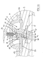
- the channel 26 is extended beyond the access point of the channel 25 also to a valve 32 mounted in the middle part 3 and in the upper part 4 for limiting the liquid volume flow output by the balloon 16.
- This valve 32 is formed by a resiliently held on the edge side between middle part 3 and upper part 4 valve diaphragm 33, a cooperating with this valve core 34, a on the valve diaphragm 33 and the upper part 4 supporting compression spring 35 and mounted in a thread of the upper part 4 screw 36, which is engageable in operative connection with the valve membrane 33 formed.
- the channel 26 opens into a radially extending channel 37 of the valve diaphragm 33 and from there into a radial channel 38 of the Veritil stresses 34, which opens into an axial channel 39 of the valve core 34.
- This channel 39 is open in the region of its, a reinforced portion 40 of the valve diaphragm 33 facing the end.
- a stop which is designed as a set screw 36, is arranged on the side facing away from the channel 39 of the portion 40, which plays the role of a closure element.
- this attack could also be stationary.
- the valve core 34 is held axially immovably with respect to the valve diaphragm 33 and, moreover, also with respect to this not rotatable.
- two separate chambers 42 and 43 are formed, which are connected to each other via a valve core 34 passing through, arranged parallel to the channel 40 channel 44.
- the chamber 42 which lies in the flow direction for access, thus to the channel 26, serves as a barrier chamber.
- the chamber 43 is located in the flow direction to the outlet 45.
- a filter 46 is provided which is clamped at the edge between the middle part 3 and the lower part 5.
- the liquid reaches a channel 47 which is in fluid communication with the outlet 45 (FIG. 5) and from there to a LuerLock connection 48 held between the central part 3 and the lower part 5 Luer-lock connector 49 connected, which is provided with a hose 50 which leads to the patient.
- a glass capillary 53 is inserted into the channel 47.
- This is a flow restrictor capable of limiting the volume flow exiting the pump through channel 47 because the flow restrictor has a smaller cross-section than the in-port channel 37.
- the flow restrictor may be designed differently than in the manner of a glass capillary. It is quite conceivable, behind the valve in the outlet of the pump, for example, a meander chip, which limits the flow to provide.
- valve diaphragm 33 In an initial situation, the valve diaphragm 33 is in the position shown in FIG. 13, in which the valve diaphragm 33 largely bears against the central part 3, without it being necessary for the compression spring 35 to act. Due to the positioning of the valve core 34 with respect to the portion 40 of the valve diaphragm 33, a small gap between the portion 40 and a circumferential, thus annular projection 54 of the valve core 34 is given. As a result, liquid flows via the channel 13 of the core 11 and the subsequent, housing-side channel 26 into the channel 37 of the valve membrane 33 and from there into the channels 38 and 39 of the valve core 34.
- the liquid flows through the gap formed between the projection 54 and the portion 40 of the valve membrane 33 into the chamber 42 located there, and from the chamber 42 via the channel 44 between valve membrane 33 and valve core 34 to the chamber 43, passes the filter 46 and passes through the outlet 45 to the channel 47 with the flow restrictor 53.
- valve diaphragm 33 which is clamped in the edge region between the central part 3 and the upper part 4, in the central region in the direction de
- the valve diaphragm 34 reaches with its portion 40 against the projection 55 of the adjusting screw 36, which faces the portion 40, contacted the section 40 there, the adjusting screw 36, which because the valve diaphragm 33 can not move further upward in the direction of the upper shell, the portion 40 is pressed against the projection 54 of the valve core 34 and thus closes the flow through the channel 39.
- the liquid pump could be modified in such a way that only one device is provided for substantially keeping the liquid volume flow output by the elastic element or a device for limiting the liquid volume flow output by the elastic element.
- liquid Prior to using the mechanically operated liquid pump liquid is supplied through the Luer-lock valve 21, whereby the liquid enters the balloon 16 and the level of the balloon can be read through the transparent hood 29 on the basis of the marks 51 mounted in the transverse direction of the hood which are a reference for the transverse extent of the balloon as a function of its filling.
- the marks 51 mounted in the transverse direction of the hood which are a reference for the transverse extent of the balloon as a function of its filling.
- the user can use the pump anywhere, instantly, without longer start-up times. It can be used by the user as well as statically, in all normal areas of life outside, as in medicine.
- the pump can be sterilized and ensures a minimum of handling / handling effort.
- the pump is inexpensive to produce due to the simple construction of the few components. This is a prerequisite for being able to be used especially in outpatient and financially weak markets.
- the low weight of the pump allows use in accident, emergency, hospital and disaster areas.
- the functional elements of the pump can be replaced individually or as a whole.
- the pump is suitable for short or long delivery times, for example with a balloon with a capacity of 25 ml for a flow rate of 2.5 ml per hour, thus a running time of 10 hours.
- balloons can be used, which have different volumes, for. B. 10 ml, 50 ml, 100 ml or 150 ml.
- the duration may well be much longer, for example, up to 24 hours.
- flow rates of> 1000 ml per hour are quite conceivable, the preferred application is a flow rate of 0.5 to 10 ml per hour.
- an injection-molded balloon which serves as a collecting container for the drug solution and pressure reservoir.
- the balloon has a defined contour in cross-section and in the expansion, for filling flat housing spaces and to avoid pressure peaks. It is radially and / or axially biased by a single or multi-part core, to increase the restoring forces.
- the balloon is fixed on one side over the core stationary by means of a clamping ring form-fitting, airtight.
- the balloon is freely movable in axial and radial Direction during filling and emptying, while elastically deformable and can move without friction within the hood.
- the pump 1 may additionally be provided with a bolus reservoir.
- a bolus reservoir illustrated by the reference numeral 52. If necessary, the pump can be converted in this respect.
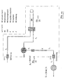
- FIG. 14 is a diagram illustrating the principle of operation of the previously described mechanically operated liquid pump with indication of the physical quantities. With dash-dotted line the contour of the pump is illustrated.
- FIG. 15 shows, with regard to the bolus shot implementation, behind the capillary K, thus behind the device for largely keeping constant the volume flow of liquid delivered by the elastic element BK, the bolus reservoir BR.
- the leading to the capillary K line is designated ZF, the leading away from the bolus reservoir line with AF.
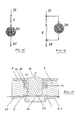
- FIG. 16 shows, in contrast to the series connection of capillary K and bolus reservoir BR shown in FIG. 15, their parallel connection.
- FIG. 17 illustrates the design of the bolus reservoir instead of the bolus providence designated by the reference numeral 52 in FIG. 1.
- the channel 47 opens downstream of the capillary 53 (FIG. 5) into a depression in the lower part 5 trained bolus chamber 56 which is sealed by an elastic membrane 57 which is clamped between the middle part 3 and the lower part 5 in the edge region, opposite a recess 58 in the middle part 3.
- the recess 58 serves to receive a plunger 59, which is displaceable in the direction of the arrow F against the restoring force of an elastic silicone ring 60 against the membrane 57 so that it moves the membrane 57 into the bolus chamber 56, which abruptly liquid from the bolus chamber 56 to Outlet of the pump, thus exiting to the LuerLock connection 48.
- a plunger 59 which is displaceable in the direction of the arrow F against the restoring force of an elastic silicone ring 60 against the membrane 57 so that it moves the membrane 57 into the bolus chamber 56, which abruptly liquid from the bolus chamber 56 to Outlet of the pump, thus exiting to the LuerLock connection 48.
- the elastic silicone ring may for example also be provided a compression spring which surrounds the plunger 59 and has the task to transfer this in his the bolus chamber 56 releasing position, as illustrated in Figure 17.
Priority Applications (16)
| Application Number | Priority Date | Filing Date | Title |
|---|---|---|---|
| EP05015967A EP1745813A1 (de) | 2005-07-22 | 2005-07-22 | Mechanisch betriebene Flüssigkeitspumpe |
| AT05015966T ATE415989T1 (de) | 2005-07-22 | 2005-07-22 | Ventil für ein fluid, insbesondere zur verwendung in einer mechanisch betriebenen flüssigkeitspumpe |
| EP05015965A EP1746479A1 (de) | 2005-07-22 | 2005-07-22 | Mechanisch betriebene Flüssigkeitspumpe |
| DE502005006146T DE502005006146D1 (de) | 2005-07-22 | 2005-07-22 | Ventil für ein Fluid, insbesondere zur Verwendung in einer mechanisch betriebenen Flüssigkeitspumpe |
| EP08006187A EP1944672A3 (de) | 2005-07-22 | 2005-07-22 | Mechanisch betriebene Flüssigkeitspumpe |
| EP05015966A EP1745812B1 (de) | 2005-07-22 | 2005-07-22 | Ventil für ein Fluid, insbesondere zur Verwendung in einer mechanisch betriebenen Flüssigkeitspumpe |
| ES05015966T ES2318389T3 (es) | 2005-07-22 | 2005-07-22 | Valvula para un fluido, especialmente para uso en una bomba de liquido mecanicamente impulsada. |
| PL05015966T PL1745812T3 (pl) | 2005-07-22 | 2005-07-22 | Zawór dla płynu, zwłaszcza do stosowania w pompie cieczowej napędzanej mechanicznie |
| JP2008526394A JP2009517090A (ja) | 2005-07-22 | 2006-07-21 | 機械的に作動せしめられる液体ポンプ |
| PCT/EP2006/007204 WO2007009809A2 (de) | 2005-07-22 | 2006-07-21 | Mechanisch betriebene flüssigkeitspumpe |
| JP2008526393A JP2009503417A (ja) | 2005-07-22 | 2006-07-21 | 特に機械的に作動せしめられる液体ポンプに使用するための流体用弁 |
| US11/989,255 US20090214364A1 (en) | 2005-07-22 | 2006-07-21 | Mechanical liquid pump |
| US11/989,253 US20090306593A1 (en) | 2005-07-22 | 2006-07-21 | Mechanically operated liquid pump |
| JP2008526392A JP2009502448A (ja) | 2005-07-22 | 2006-07-21 | 機械的に作動せしめられる液体ポンプ |
| PCT/EP2006/007192 WO2007009808A1 (de) | 2005-07-22 | 2006-07-21 | Ventil für ein fluid, insbesondere zur verwendung in einer mechanisch betriebenen flüssigkeitspumpe |
| PCT/EP2006/007191 WO2007009807A1 (de) | 2005-07-22 | 2006-07-21 | Mechanisch betriebene flüssigkeitspumpe |
Applications Claiming Priority (3)
| Application Number | Priority Date | Filing Date | Title |
|---|---|---|---|
| EP05015966A EP1745812B1 (de) | 2005-07-22 | 2005-07-22 | Ventil für ein Fluid, insbesondere zur Verwendung in einer mechanisch betriebenen Flüssigkeitspumpe |
| EP05015967A EP1745813A1 (de) | 2005-07-22 | 2005-07-22 | Mechanisch betriebene Flüssigkeitspumpe |
| EP05015965A EP1746479A1 (de) | 2005-07-22 | 2005-07-22 | Mechanisch betriebene Flüssigkeitspumpe |
Related Child Applications (1)
| Application Number | Title | Priority Date | Filing Date |
|---|---|---|---|
| EP08006187A Division EP1944672A3 (de) | 2005-07-22 | 2005-07-22 | Mechanisch betriebene Flüssigkeitspumpe |
Publications (1)
| Publication Number | Publication Date |
|---|---|
| EP1746479A1 true EP1746479A1 (de) | 2007-01-24 |
Family
ID=39530453
Family Applications (4)
| Application Number | Title | Priority Date | Filing Date |
|---|---|---|---|
| EP05015966A Not-in-force EP1745812B1 (de) | 2005-07-22 | 2005-07-22 | Ventil für ein Fluid, insbesondere zur Verwendung in einer mechanisch betriebenen Flüssigkeitspumpe |
| EP05015967A Withdrawn EP1745813A1 (de) | 2005-07-22 | 2005-07-22 | Mechanisch betriebene Flüssigkeitspumpe |
| EP08006187A Withdrawn EP1944672A3 (de) | 2005-07-22 | 2005-07-22 | Mechanisch betriebene Flüssigkeitspumpe |
| EP05015965A Ceased EP1746479A1 (de) | 2005-07-22 | 2005-07-22 | Mechanisch betriebene Flüssigkeitspumpe |
Family Applications Before (3)
| Application Number | Title | Priority Date | Filing Date |
|---|---|---|---|
| EP05015966A Not-in-force EP1745812B1 (de) | 2005-07-22 | 2005-07-22 | Ventil für ein Fluid, insbesondere zur Verwendung in einer mechanisch betriebenen Flüssigkeitspumpe |
| EP05015967A Withdrawn EP1745813A1 (de) | 2005-07-22 | 2005-07-22 | Mechanisch betriebene Flüssigkeitspumpe |
| EP08006187A Withdrawn EP1944672A3 (de) | 2005-07-22 | 2005-07-22 | Mechanisch betriebene Flüssigkeitspumpe |
Country Status (8)
| Country | Link |
|---|---|
| US (2) | US20090214364A1 (pl) |
| EP (4) | EP1745812B1 (pl) |
| JP (3) | JP2009517090A (pl) |
| AT (1) | ATE415989T1 (pl) |
| DE (1) | DE502005006146D1 (pl) |
| ES (1) | ES2318389T3 (pl) |
| PL (1) | PL1745812T3 (pl) |
| WO (3) | WO2007009809A2 (pl) |
Cited By (1)
| Publication number | Priority date | Publication date | Assignee | Title |
|---|---|---|---|---|
| WO2017108176A1 (de) * | 2015-12-21 | 2017-06-29 | Fresenius Medical Care Deutschland Gmbh | Blutbehandlungsgerät umfassend eine dosierleitung mit einer membranpumpe und einem ventil und verfahren zur dosierung |
Families Citing this family (8)
| Publication number | Priority date | Publication date | Assignee | Title |
|---|---|---|---|---|
| US8038650B2 (en) * | 2010-02-22 | 2011-10-18 | Microsert Ltd. | Slow release liquid drug delivery device |
| KR101503715B1 (ko) | 2012-10-15 | 2015-03-24 | 에이스메디칼 주식회사 | 조립이 용이하고 주입된 약물이 모두 배출되는 약액 공급장치. |
| WO2014204894A2 (en) | 2013-06-18 | 2014-12-24 | Enable Injections, Llc | Vial transfer and injection apparatus and method |
| CN106029129B (zh) * | 2013-12-20 | 2020-10-02 | 赛诺菲-安万特德国有限公司 | 用于药物输送装置的一次性药筒 |
| KR101695454B1 (ko) * | 2015-07-08 | 2017-01-12 | (주)더블유앤지 | 스냅 결합 방식의 벌룬 인퓨저 |
| KR101811846B1 (ko) * | 2017-03-15 | 2017-12-22 | 김휘화 | 안전성을 향상시킨 반자동 주사기 |
| US11344670B2 (en) * | 2019-10-03 | 2022-05-31 | Mark Shal | Small non-electrically driven portable infusion device |
| CN116099079B (zh) * | 2023-03-31 | 2023-11-21 | 常州瑞神安医疗器械有限公司 | 一种植入式药物输注泵 |
Citations (8)
| Publication number | Priority date | Publication date | Assignee | Title |
|---|---|---|---|---|
| US3386469A (en) * | 1966-07-29 | 1968-06-04 | Robertshaw Controls Co | Pressure regulator |
| US4769008A (en) | 1986-11-26 | 1988-09-06 | Infusion Systems Corporation | Pressurized fluid dispenser |
| EP0424494B1 (en) | 1989-04-21 | 1994-03-02 | Baxter International Inc. | Continuous/bolus infusor |
| EP0812596A1 (de) * | 1996-06-14 | 1997-12-17 | Filtertek, S.A. | Schwerkraft-Infusionsvorrichtung für medizinische Infusionen |
| EP0944405B1 (en) | 1997-12-24 | 2002-02-13 | Baxter International Inc. | Enclosed ambulatory pump |
| DE10058121A1 (de) | 2000-11-22 | 2002-05-23 | Roland Wex | Mechanisch betriebene Flüssigkeitspumpe |
| EP1321156A1 (de) | 2001-12-19 | 2003-06-25 | WEX, Roland | Ventil zum weitgehenden Konstanthalten eines Flüssigkeitsstromes |
| US20040168723A1 (en) | 2003-02-28 | 2004-09-02 | Baxter International Inc. | Pressure regulator for infusor |
Family Cites Families (17)
| Publication number | Priority date | Publication date | Assignee | Title |
|---|---|---|---|---|
| US3469578A (en) * | 1965-10-12 | 1969-09-30 | Howard R Bierman | Infusion device for ambulatory patients with flow control means |
| US3511472A (en) | 1968-01-12 | 1970-05-12 | American Air Filter Co | Limiting flow valve |
| GB1562321A (en) | 1976-01-13 | 1980-03-12 | Ici Ltd | Pump |
| FR2597186B1 (fr) | 1986-04-14 | 1990-01-12 | Europ Propulsion | Soupape ou vanne fonctionnant sans frottement |
| US5120315A (en) | 1986-11-26 | 1992-06-09 | 501 Baxter International, Inc. | Pressurized fluid dispenser |
| KR0141688B1 (ko) * | 1989-05-24 | 1998-06-15 | 스까다 쇼오에이 | 액체형 약제를 연속적으로 주입하기 위한 기구를 가진 주입기 |
| US5336188A (en) | 1989-06-16 | 1994-08-09 | Science Incorporated | Fluid delivery apparatus having a stored energy source |
| US5169389A (en) * | 1989-06-16 | 1992-12-08 | Science, Inc. | Fluid delivery apparatus |
| IL95660A (en) * | 1990-09-12 | 1994-02-27 | Bron Dan | Pressure-compensated infusion regulator |
| DE4436540C2 (de) | 1994-10-13 | 1997-03-06 | Fresenius Ag | Sperrvorrichtung für eine Vorrichtung zum Zuführen eines flüssigen Medikaments unter Druck |
| US5616127A (en) | 1994-11-14 | 1997-04-01 | Smith; Kevin | Expandable liquid infusion device |
| US6176845B1 (en) * | 1996-12-18 | 2001-01-23 | Science Incorporated | Fluid delivery apparatus with flow indicator and vial fill |
| JP3207799B2 (ja) | 1997-12-03 | 2001-09-10 | 株式会社パイオラックス | 薬液持続注入器 |
| DE19826675A1 (de) | 1997-06-21 | 1999-03-04 | Haindl Hans | Beutel zur wenigstens teilweisen Umfassung eines Herzens |
| JP4585060B2 (ja) * | 1999-09-22 | 2010-11-24 | オーベクス株式会社 | 流量制御装置 |
| US6416495B1 (en) * | 2000-10-10 | 2002-07-09 | Science Incorporated | Implantable fluid delivery device for basal and bolus delivery of medicinal fluids |
| DE10063975A1 (de) | 2000-12-20 | 2002-06-27 | Roland Wex | Mechanisch betriebene Flüssigkeitspumpe |
-
2005
- 2005-07-22 PL PL05015966T patent/PL1745812T3/pl unknown
- 2005-07-22 DE DE502005006146T patent/DE502005006146D1/de active Active
- 2005-07-22 AT AT05015966T patent/ATE415989T1/de not_active IP Right Cessation
- 2005-07-22 EP EP05015966A patent/EP1745812B1/de not_active Not-in-force
- 2005-07-22 EP EP05015967A patent/EP1745813A1/de not_active Withdrawn
- 2005-07-22 ES ES05015966T patent/ES2318389T3/es active Active
- 2005-07-22 EP EP08006187A patent/EP1944672A3/de not_active Withdrawn
- 2005-07-22 EP EP05015965A patent/EP1746479A1/de not_active Ceased
-
2006
- 2006-07-21 US US11/989,255 patent/US20090214364A1/en not_active Abandoned
- 2006-07-21 WO PCT/EP2006/007204 patent/WO2007009809A2/de active Application Filing
- 2006-07-21 WO PCT/EP2006/007192 patent/WO2007009808A1/de active Application Filing
- 2006-07-21 WO PCT/EP2006/007191 patent/WO2007009807A1/de active Application Filing
- 2006-07-21 JP JP2008526394A patent/JP2009517090A/ja active Pending
- 2006-07-21 JP JP2008526392A patent/JP2009502448A/ja active Pending
- 2006-07-21 US US11/989,253 patent/US20090306593A1/en not_active Abandoned
- 2006-07-21 JP JP2008526393A patent/JP2009503417A/ja active Pending
Patent Citations (8)
| Publication number | Priority date | Publication date | Assignee | Title |
|---|---|---|---|---|
| US3386469A (en) * | 1966-07-29 | 1968-06-04 | Robertshaw Controls Co | Pressure regulator |
| US4769008A (en) | 1986-11-26 | 1988-09-06 | Infusion Systems Corporation | Pressurized fluid dispenser |
| EP0424494B1 (en) | 1989-04-21 | 1994-03-02 | Baxter International Inc. | Continuous/bolus infusor |
| EP0812596A1 (de) * | 1996-06-14 | 1997-12-17 | Filtertek, S.A. | Schwerkraft-Infusionsvorrichtung für medizinische Infusionen |
| EP0944405B1 (en) | 1997-12-24 | 2002-02-13 | Baxter International Inc. | Enclosed ambulatory pump |
| DE10058121A1 (de) | 2000-11-22 | 2002-05-23 | Roland Wex | Mechanisch betriebene Flüssigkeitspumpe |
| EP1321156A1 (de) | 2001-12-19 | 2003-06-25 | WEX, Roland | Ventil zum weitgehenden Konstanthalten eines Flüssigkeitsstromes |
| US20040168723A1 (en) | 2003-02-28 | 2004-09-02 | Baxter International Inc. | Pressure regulator for infusor |
Cited By (4)
| Publication number | Priority date | Publication date | Assignee | Title |
|---|---|---|---|---|
| WO2017108176A1 (de) * | 2015-12-21 | 2017-06-29 | Fresenius Medical Care Deutschland Gmbh | Blutbehandlungsgerät umfassend eine dosierleitung mit einer membranpumpe und einem ventil und verfahren zur dosierung |
| CN108474366A (zh) * | 2015-12-21 | 2018-08-31 | 费森尤斯医疗护理德国有限责任公司 | 包括具有隔膜泵和阀的配给管路的血液治疗仪和用于配给的方法 |
| CN108474366B (zh) * | 2015-12-21 | 2020-06-26 | 费森尤斯医疗护理德国有限责任公司 | 包括具有隔膜泵和阀的配给管路的血液治疗仪和用于配给的方法 |
| US11311659B2 (en) | 2015-12-21 | 2022-04-26 | Fresenius Medical Care Deutschland Gmbh | Blood treatment device comprising a metering line having a membrane pump and a valve and method for metering |
Also Published As
| Publication number | Publication date |
|---|---|
| JP2009503417A (ja) | 2009-01-29 |
| JP2009502448A (ja) | 2009-01-29 |
| WO2007009809A3 (de) | 2007-05-10 |
| PL1745812T3 (pl) | 2009-06-30 |
| EP1745812B1 (de) | 2008-12-03 |
| ATE415989T1 (de) | 2008-12-15 |
| EP1944672A3 (de) | 2008-07-30 |
| WO2007009808A1 (de) | 2007-01-25 |
| WO2007009809A2 (de) | 2007-01-25 |
| JP2009517090A (ja) | 2009-04-30 |
| EP1745812A1 (de) | 2007-01-24 |
| WO2007009807A1 (de) | 2007-01-25 |
| US20090214364A1 (en) | 2009-08-27 |
| DE502005006146D1 (de) | 2009-01-15 |
| US20090306593A1 (en) | 2009-12-10 |
| ES2318389T3 (es) | 2009-05-01 |
| EP1944672A2 (de) | 2008-07-16 |
| EP1745813A1 (de) | 2007-01-24 |
Similar Documents
| Publication | Publication Date | Title |
|---|---|---|
| EP1746479A1 (de) | Mechanisch betriebene Flüssigkeitspumpe | |
| DE60132909T2 (de) | Implantierbare medizinische vorrichtung zum abgeben einer flüssigkeit | |
| WO1994012225A1 (de) | Kassetteninfusionssystem | |
| CH636768A5 (de) | Einpflanzbare infusionsvorrichtung. | |
| WO2011076382A1 (de) | Implantierbares shuntsystem | |
| DE10226643A1 (de) | Kolbenstopfen für Injektionsvorrichtung, Produktbehälter und Injektionsvorrichtung | |
| DE2652197A1 (de) | Druckpumpe fuer eine infusionsvorrichtung | |
| DE4436540A1 (de) | Infusionssystem zur kontinuierlichen Abgabe eines flüssigen Medikaments unter Druck | |
| WO2012163372A1 (de) | Vorrichtung für den stoff- und/oder energieaustausch zwischen zwei medien | |
| EP2525865A2 (de) | Fluiddurchströmte verbindungssysteme zum einsatz in der medizin und medizintechnik | |
| WO2017140849A1 (de) | Ventileinheit für eine anlage zur herstellung einer medizinischen zubereitung | |
| DE19642234C1 (de) | Implantierbare Infusionspumpe | |
| DE102013114336A1 (de) | Dosierung entnehmbar | |
| EP3325045A1 (de) | Betätigungsvorrichtung zur bolusverabreichung | |
| WO1980002506A1 (en) | Needle for a perfusion device | |
| DE102010029573A1 (de) | Mikropumpe | |
| DE19928133C2 (de) | Mechanisch betriebene Flüssigkeitspumpe | |
| DE3035748C2 (de) | Infusionsgerät | |
| EP3628345B1 (de) | Kit zur modularen ausbildung einer medizinischen pumpvorrichtung sowie medizinische pumpvorrichtung | |
| DE102010005135A1 (de) | Vorrichtung für den Stoff- und/oder Energieaustausch zwischen zwei Medien | |
| WO2000078377A1 (de) | Mechanisch betriebene flüssigkeitspumpe | |
| EP0489297A1 (de) | Infusionsanordnung mit einer Einrichtung zum Abführen eines Bolusvolumens | |
| DE10058121A1 (de) | Mechanisch betriebene Flüssigkeitspumpe | |
| EP0641933B1 (de) | Dosiervorrichtung | |
| DE1911219A1 (de) | T-Verbindungsstueck mit Doppelventil |
Legal Events
| Date | Code | Title | Description |
|---|---|---|---|
| PUAI | Public reference made under article 153(3) epc to a published international application that has entered the european phase |
Free format text: ORIGINAL CODE: 0009012 |
|
| AK | Designated contracting states |
Kind code of ref document: A1 Designated state(s): AT BE BG CH CY CZ DE DK EE ES FI FR GB GR HU IE IS IT LI LT LU LV MC NL PL PT RO SE SI SK TR |
|
| AX | Request for extension of the european patent |
Extension state: AL BA HR MK YU |
|
| 17P | Request for examination filed |
Effective date: 20070709 |
|
| 17Q | First examination report despatched |
Effective date: 20070810 |
|
| AKX | Designation fees paid |
Designated state(s): AT BE BG CH CY CZ DE DK EE ES FI FR GB GR HU IE IS IT LI LT LU LV MC NL PL PT RO SE SI SK TR |
|
| STAA | Information on the status of an ep patent application or granted ep patent |
Free format text: STATUS: THE APPLICATION HAS BEEN REFUSED |
|
| 18R | Application refused |
Effective date: 20090206 |