EP1746366A1 - Condenseur du type tuyau-plaque pour des installations frigorifiques - Google Patents
Condenseur du type tuyau-plaque pour des installations frigorifiques Download PDFInfo
- Publication number
- EP1746366A1 EP1746366A1 EP06015143A EP06015143A EP1746366A1 EP 1746366 A1 EP1746366 A1 EP 1746366A1 EP 06015143 A EP06015143 A EP 06015143A EP 06015143 A EP06015143 A EP 06015143A EP 1746366 A1 EP1746366 A1 EP 1746366A1
- Authority
- EP
- European Patent Office
- Prior art keywords
- tube
- pipe
- plate
- sheet
- liquefier
- Prior art date
- Legal status (The legal status is an assumption and is not a legal conclusion. Google has not performed a legal analysis and makes no representation as to the accuracy of the status listed.)
- Withdrawn
Links
Images

Classifications
-
- F—MECHANICAL ENGINEERING; LIGHTING; HEATING; WEAPONS; BLASTING
- F28—HEAT EXCHANGE IN GENERAL
- F28F—DETAILS OF HEAT-EXCHANGE AND HEAT-TRANSFER APPARATUS, OF GENERAL APPLICATION
- F28F21/00—Constructions of heat-exchange apparatus characterised by the selection of particular materials
- F28F21/08—Constructions of heat-exchange apparatus characterised by the selection of particular materials of metal
- F28F21/081—Heat exchange elements made from metals or metal alloys
- F28F21/084—Heat exchange elements made from metals or metal alloys from aluminium or aluminium alloys
-
- F—MECHANICAL ENGINEERING; LIGHTING; HEATING; WEAPONS; BLASTING
- F25—REFRIGERATION OR COOLING; COMBINED HEATING AND REFRIGERATION SYSTEMS; HEAT PUMP SYSTEMS; MANUFACTURE OR STORAGE OF ICE; LIQUEFACTION SOLIDIFICATION OF GASES
- F25B—REFRIGERATION MACHINES, PLANTS OR SYSTEMS; COMBINED HEATING AND REFRIGERATION SYSTEMS; HEAT PUMP SYSTEMS
- F25B39/00—Evaporators; Condensers
- F25B39/04—Condensers
-
- F—MECHANICAL ENGINEERING; LIGHTING; HEATING; WEAPONS; BLASTING
- F28—HEAT EXCHANGE IN GENERAL
- F28D—HEAT-EXCHANGE APPARATUS, NOT PROVIDED FOR IN ANOTHER SUBCLASS, IN WHICH THE HEAT-EXCHANGE MEDIA DO NOT COME INTO DIRECT CONTACT
- F28D1/00—Heat-exchange apparatus having stationary conduit assemblies for one heat-exchange medium only, the media being in contact with different sides of the conduit wall, in which the other heat-exchange medium is a large body of fluid, e.g. domestic or motor car radiators
- F28D1/02—Heat-exchange apparatus having stationary conduit assemblies for one heat-exchange medium only, the media being in contact with different sides of the conduit wall, in which the other heat-exchange medium is a large body of fluid, e.g. domestic or motor car radiators with heat-exchange conduits immersed in the body of fluid
- F28D1/04—Heat-exchange apparatus having stationary conduit assemblies for one heat-exchange medium only, the media being in contact with different sides of the conduit wall, in which the other heat-exchange medium is a large body of fluid, e.g. domestic or motor car radiators with heat-exchange conduits immersed in the body of fluid with tubular conduits
- F28D1/047—Heat-exchange apparatus having stationary conduit assemblies for one heat-exchange medium only, the media being in contact with different sides of the conduit wall, in which the other heat-exchange medium is a large body of fluid, e.g. domestic or motor car radiators with heat-exchange conduits immersed in the body of fluid with tubular conduits the conduits being bent, e.g. in a serpentine or zig-zag
- F28D1/0477—Heat-exchange apparatus having stationary conduit assemblies for one heat-exchange medium only, the media being in contact with different sides of the conduit wall, in which the other heat-exchange medium is a large body of fluid, e.g. domestic or motor car radiators with heat-exchange conduits immersed in the body of fluid with tubular conduits the conduits being bent, e.g. in a serpentine or zig-zag the conduits being bent in a serpentine or zig-zag
-
- F—MECHANICAL ENGINEERING; LIGHTING; HEATING; WEAPONS; BLASTING
- F28—HEAT EXCHANGE IN GENERAL
- F28F—DETAILS OF HEAT-EXCHANGE AND HEAT-TRANSFER APPARATUS, OF GENERAL APPLICATION
- F28F1/00—Tubular elements; Assemblies of tubular elements
- F28F1/10—Tubular elements and assemblies thereof with means for increasing heat-transfer area, e.g. with fins, with projections, with recesses
- F28F1/12—Tubular elements and assemblies thereof with means for increasing heat-transfer area, e.g. with fins, with projections, with recesses the means being only outside the tubular element
- F28F1/14—Tubular elements and assemblies thereof with means for increasing heat-transfer area, e.g. with fins, with projections, with recesses the means being only outside the tubular element and extending longitudinally
- F28F1/22—Tubular elements and assemblies thereof with means for increasing heat-transfer area, e.g. with fins, with projections, with recesses the means being only outside the tubular element and extending longitudinally the means having portions engaging further tubular elements
-
- F—MECHANICAL ENGINEERING; LIGHTING; HEATING; WEAPONS; BLASTING
- F28—HEAT EXCHANGE IN GENERAL
- F28F—DETAILS OF HEAT-EXCHANGE AND HEAT-TRANSFER APPARATUS, OF GENERAL APPLICATION
- F28F21/00—Constructions of heat-exchange apparatus characterised by the selection of particular materials
- F28F21/08—Constructions of heat-exchange apparatus characterised by the selection of particular materials of metal
- F28F21/081—Heat exchange elements made from metals or metal alloys
- F28F21/082—Heat exchange elements made from metals or metal alloys from steel or ferrous alloys
-
- F—MECHANICAL ENGINEERING; LIGHTING; HEATING; WEAPONS; BLASTING
- F25—REFRIGERATION OR COOLING; COMBINED HEATING AND REFRIGERATION SYSTEMS; HEAT PUMP SYSTEMS; MANUFACTURE OR STORAGE OF ICE; LIQUEFACTION SOLIDIFICATION OF GASES
- F25B—REFRIGERATION MACHINES, PLANTS OR SYSTEMS; COMBINED HEATING AND REFRIGERATION SYSTEMS; HEAT PUMP SYSTEMS
- F25B2339/00—Details of evaporators; Details of condensers
- F25B2339/04—Details of condensers
- F25B2339/045—Condensers made by assembling a tube on a plate-like element or between plate-like elements
-
- F—MECHANICAL ENGINEERING; LIGHTING; HEATING; WEAPONS; BLASTING
- F28—HEAT EXCHANGE IN GENERAL
- F28D—HEAT-EXCHANGE APPARATUS, NOT PROVIDED FOR IN ANOTHER SUBCLASS, IN WHICH THE HEAT-EXCHANGE MEDIA DO NOT COME INTO DIRECT CONTACT
- F28D21/00—Heat-exchange apparatus not covered by any of the groups F28D1/00 - F28D20/00
- F28D2021/0019—Other heat exchangers for particular applications; Heat exchange systems not otherwise provided for
- F28D2021/0068—Other heat exchangers for particular applications; Heat exchange systems not otherwise provided for for refrigerant cycles
- F28D2021/007—Condensers
Definitions
- the present invention relates to a tube / plate liquefier for a cooling circuit of a refrigerator and / or freezer, with a preferably meandering curved tube in which the cooling circuit medium is liquefied, and a support panel made of sheet metal, to which the tube is attached.
- Such a tube / plate liquefier for refrigerators and / or freezers is for example from the DE 20 2004 017 652 U1 known.
- Such meshwandvertheer consist of a steel sheet on which the meandering curved steel pipe is placed and fixed, wherein regularly both the steel sheet and the steel pipe are painted. Since in such condensers, the heat dissipation is limited, the meandering curved tube must have a correspondingly large length and the heat dissipation serving to the environment support panel made of sheet metal a correspondingly large area so that the vaporized refrigerant in the evaporator of the refrigeration circuit sufficiently cooled when flowing through the pipe and so that it is liquefied again.
- DE 20 2004 017 652 U1 proposes to improve the heat dissipation, the meandering reciprocating condenser tube with a certain bending radius provided and thus give the straight lines a predetermined distance, as this is to achieve a more uniform heat radiation over the surface of the carrier panel. Nevertheless, the heat dissipation remains limited and thus the necessary Auspaneel Structure and tube length considerable.
- the present invention is based on the object to provide an improved condenser of the type mentioned, which avoids the disadvantages of the prior art and the latter further develops in an advantageous manner.
- a further improved heat dissipation and / or a smaller size of the condenser should be achieved.
- the present invention is based on the consideration that the heat dissipation of the evaporator can be effectively improved on the one hand by increasing the thermal conductivity of the carrier panel and on the other hand by increasing the heat transfer from the condenser to the plate of the carrier panel, both of which are particularly by a special Material pairing between the material of the carrier panel and the material of the tube can be achieved.
- the support panel consists of an aluminum sheet, while the pipe is a steel pipe or an aluminum pipe.
- the pipe is a steel pipe or an aluminum pipe.
- the aluminum sheet has a significantly better thermal conductivity compared to the previously customary steel sheets.
- the tube can be positively and / or non-positively connected to the carrier panel.
- the carrier panel may according to an advantageous embodiment of the invention have curved tube receiving channels, in which the tube is inserted, so that the aluminum sheet encloses the tube surface.
- the tube receiving channels surround the tube in cross section by more than 180 °, so that the heat transfer surface and thus the heat dissipation is particularly large. In addition, this ensures a firm connection between sheet and tube.
- a press or clamping fit is provided between the tube receiving channels and the tube.
- the tube can basically be added differently in the tube receiving channels.
- the tube may be rolled into the aluminum sheet in the region of the tube receiving channels.
- the support panel can in principle be made of a single sheet metal sheet, but it is alternatively also possible to assemble the support panel from several pieces of sheet metal.
- the support panel may consist in particular of a plurality of overlapping metal strips, if the tube is not rolled into the aluminum sheet, but is taken up between overlapping metal strips of the carrier panel. As a result, a complete enclosure of the tube of the material of the carrier panel can be achieved.
- a steel tube is used as condenser tube, this can basically be a bare steel tube without surface coating or treatment. Alternatively, a particularly favorable combination of materials results even when galvanized Steel tube is used. The same applies to tin-plated steel pipe. This also makes it possible to achieve a particularly favorable heat transfer.
- the aluminum sheet support panel and / or the condenser tube may be left unpainted according to an embodiment of the invention.
- a painting can be provided as an alternative.
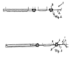
- the condenser 1 shown in FIG. 1 comprises a substantially plate-shaped carrier panel 2 and a condenser tube 3 connected thereto, which is guided back and forth in meandering fashion and has an inlet 4 and an outlet 5.
- the refrigerant releases the heat absorbed via the condenser tube 3 to the carrier panel 2 and via this to the environment, so that the evaporator medium or the refrigerant is cooled and re-liquefied until it flows through the outlet 5 in the subsequent functional unit of the refrigeration cycle is initiated again.
- the carrier panel 2 is made of a sheet of aluminum or an aluminum alloy.
- the tube 3 may also consist of aluminum or an aluminum alloy according to an embodiment of the invention.
- a condenser tube 3 a steel tube may be used, which may be galvanized according to an embodiment of the invention or tinned according to an alternative embodiment of the invention.
- the condenser tube 3 is not simply placed on the carrier panel 2 of the condenser. Rather, the carrier panel 2 has substantially rectilinearly extending tube receiving channels 6, in which the condenser tube 3 is inserted and in which the condenser tube 3 is wrapped by the sheet metal of the carrier panel 2, so that on the one hand, a large contact area between the carrier panel 2 and condenser tube 3 results on the other hand, the condenser tube 3 is held positively and / or non-positively in the tube receiving channels 6.
- the tube 3 is rolled into the sheet metal of the carrier panel 2.
- the sheet metal of the carrier panel 2 is folded or curved in the shape of a channel, so that the sheet of the carrier panel 2 surrounds the tube 3 in a range of approximately 270 °.
- the carrier panel 2 is made essentially of a one-piece aluminum sheet.
- the carrier panel 2 is produced from a plurality of overlapping metal strips, wherein a tube receiving channel 6 is formed between each two overlapping metal strips 7 and 8 and the corresponding condenser tube piece is completely enclosed by the plate of the carrier panel 2 (see FIG. ,
Landscapes
- Engineering & Computer Science (AREA)
- Physics & Mathematics (AREA)
- Thermal Sciences (AREA)
- Mechanical Engineering (AREA)
- General Engineering & Computer Science (AREA)
- Geometry (AREA)
- Heat-Exchange Devices With Radiators And Conduit Assemblies (AREA)
- Devices That Are Associated With Refrigeration Equipment (AREA)
Applications Claiming Priority (2)
| Application Number | Priority Date | Filing Date | Title |
|---|---|---|---|
| DE202005011535 | 2005-07-22 | ||
| DE202005012048U DE202005012048U1 (de) | 2005-07-22 | 2005-08-01 | Rohr-/Blechverflüssiger für Kühl- und/oder Gefriergeräte |
Publications (1)
| Publication Number | Publication Date |
|---|---|
| EP1746366A1 true EP1746366A1 (fr) | 2007-01-24 |
Family
ID=37102956
Family Applications (1)
| Application Number | Title | Priority Date | Filing Date |
|---|---|---|---|
| EP06015143A Withdrawn EP1746366A1 (fr) | 2005-07-22 | 2006-07-20 | Condenseur du type tuyau-plaque pour des installations frigorifiques |
Country Status (4)
| Country | Link |
|---|---|
| US (1) | US20070023170A1 (fr) |
| EP (1) | EP1746366A1 (fr) |
| KR (1) | KR20070012206A (fr) |
| DE (1) | DE202005012048U1 (fr) |
Families Citing this family (4)
| Publication number | Priority date | Publication date | Assignee | Title |
|---|---|---|---|---|
| KR101511022B1 (ko) * | 2012-04-16 | 2015-04-10 | 주식회사 엘지화학 | 수분 제한 전극 활물질, 수분 제한 전극 및 이를 포함하는 리튬 이차전지 |
| WO2015043676A1 (fr) * | 2013-09-30 | 2015-04-02 | Arcelik Anonim Sirketi | Échangeur thermique à convection forcée pour un appareil de réfrigération |
| JP6384729B2 (ja) * | 2014-10-17 | 2018-09-05 | トヨタ自動車株式会社 | 非水電解液二次電池とその製造方法 |
| EP3757484B1 (fr) * | 2019-06-26 | 2022-07-20 | Whirlpool Corporation | Réfrigérateur |
Citations (9)
| Publication number | Priority date | Publication date | Assignee | Title |
|---|---|---|---|---|
| US2306772A (en) * | 1940-03-12 | 1942-12-29 | Mullins Mfg Corp | Sheet and tube evaporator |
| US2940737A (en) * | 1955-04-08 | 1960-06-14 | Houdaille Industries Inc | Heat exchanger |
| GB1565092A (en) * | 1977-03-25 | 1980-04-16 | T I Ltd | Making heat exchangers |
| EP0823296A2 (fr) * | 1996-08-03 | 1998-02-11 | Balcke-Dürr GmbH | Procédé de fabrication d'échangeurs de chaleur résistant à la corrosion |
| EP0844447A2 (fr) * | 1996-11-26 | 1998-05-27 | Electrolux Zanussi S.p.A. | Procédé de fabrication d'un échangeur de chaleur et échangeur ainsi obtenu |
| US5906045A (en) * | 1996-08-31 | 1999-05-25 | Daewoo Electronics Co., Ltd. | Method of manufacturing a condenser for a refrigerator |
| DE19829285A1 (de) * | 1998-06-30 | 2000-01-05 | Bsh Bosch Siemens Hausgeraete | Haushaltskältegerät, wie Haushaltskühl- oder Haushaltsgefriergerät |
| EP1411314A1 (fr) * | 2001-05-01 | 2004-04-21 | Julián Romero Beltran | Echangeur thermique de type plaque-tube |
| DE202004017652U1 (de) | 2004-11-13 | 2005-02-03 | Kenmore Thermo Kälte GmbH | Rückwandverflüssiger |
Family Cites Families (8)
| Publication number | Priority date | Publication date | Assignee | Title |
|---|---|---|---|---|
| US5423498A (en) * | 1993-04-27 | 1995-06-13 | E-Systems, Inc. | Modular liquid skin heat exchanger |
| GB9417551D0 (en) * | 1994-09-01 | 1994-10-19 | Norfrost Ltd | Improvements in or relating to refrigeration apparatus |
| IT1282559B1 (it) * | 1996-05-06 | 1998-03-27 | Whirlpool Europ S R L | Procedimento per ottenere evaporatori di circuiti frigorigeni ed evaporatore ottenuto |
| IT1296073B1 (it) * | 1997-11-06 | 1999-06-09 | Whirlpool Co | Metodo per ottenere un evaporatore monopezzo per circuiti frigorigeni ed evaporatore ottenuto |
| DE19918617C2 (de) * | 1999-04-23 | 2002-01-17 | Valeo Klimatechnik Gmbh | Gaskühler für einen überkritischen CO¶2¶-Hochdruck-Kältemittelkreislauf einer Kraftfahrzeugklimaanlage |
| WO2003091636A1 (fr) * | 2002-04-26 | 2003-11-06 | BSH Bosch und Siemens Hausgeräte GmbH | Echangeur de chaleur pour appareil de refrigeration, et procede de realisation d'un echangeur de chaleur |
| DE202004004129U1 (de) * | 2004-03-15 | 2004-06-24 | Kenmore Thermo Kälte GmbH | Wärmeaustauscher für einen Kältekreislauf |
| DE202004019829U1 (de) * | 2004-12-23 | 2005-03-10 | Kenmore Thermo Kälte GmbH | Rückwandverflüssiger |
-
2005
- 2005-08-01 DE DE202005012048U patent/DE202005012048U1/de not_active Expired - Lifetime
-
2006
- 2006-07-13 KR KR1020060065701A patent/KR20070012206A/ko not_active Application Discontinuation
- 2006-07-20 EP EP06015143A patent/EP1746366A1/fr not_active Withdrawn
- 2006-07-21 US US11/490,772 patent/US20070023170A1/en not_active Abandoned
Patent Citations (9)
| Publication number | Priority date | Publication date | Assignee | Title |
|---|---|---|---|---|
| US2306772A (en) * | 1940-03-12 | 1942-12-29 | Mullins Mfg Corp | Sheet and tube evaporator |
| US2940737A (en) * | 1955-04-08 | 1960-06-14 | Houdaille Industries Inc | Heat exchanger |
| GB1565092A (en) * | 1977-03-25 | 1980-04-16 | T I Ltd | Making heat exchangers |
| EP0823296A2 (fr) * | 1996-08-03 | 1998-02-11 | Balcke-Dürr GmbH | Procédé de fabrication d'échangeurs de chaleur résistant à la corrosion |
| US5906045A (en) * | 1996-08-31 | 1999-05-25 | Daewoo Electronics Co., Ltd. | Method of manufacturing a condenser for a refrigerator |
| EP0844447A2 (fr) * | 1996-11-26 | 1998-05-27 | Electrolux Zanussi S.p.A. | Procédé de fabrication d'un échangeur de chaleur et échangeur ainsi obtenu |
| DE19829285A1 (de) * | 1998-06-30 | 2000-01-05 | Bsh Bosch Siemens Hausgeraete | Haushaltskältegerät, wie Haushaltskühl- oder Haushaltsgefriergerät |
| EP1411314A1 (fr) * | 2001-05-01 | 2004-04-21 | Julián Romero Beltran | Echangeur thermique de type plaque-tube |
| DE202004017652U1 (de) | 2004-11-13 | 2005-02-03 | Kenmore Thermo Kälte GmbH | Rückwandverflüssiger |
Also Published As
| Publication number | Publication date |
|---|---|
| US20070023170A1 (en) | 2007-02-01 |
| DE202005012048U1 (de) | 2006-12-07 |
| KR20070012206A (ko) | 2007-01-25 |
Similar Documents
| Publication | Publication Date | Title |
|---|---|---|
| EP2409094B1 (fr) | Appareil réfrigérant | |
| DE102014011030A1 (de) | Kühl- und/oder Gefriergerät | |
| EP1746366A1 (fr) | Condenseur du type tuyau-plaque pour des installations frigorifiques | |
| DE102006002932A1 (de) | Wärmetauscher und Herstellungsverfahren für Wärmetauscher | |
| EP1307693B1 (fr) | Appareil frigorifique électroménager | |
| EP1042638B1 (fr) | Systeme d'evaporateurs | |
| DE3305764A1 (de) | Verdampfer fuer gefrierschraenke | |
| EP2158434A1 (fr) | Condenseur de paroi arrière de réfrigérateurs de ménage | |
| EP0918199B1 (fr) | Réfrigérateur | |
| EP1712857A2 (fr) | Réfrigérateur et/ou congélateur | |
| DE19850013B4 (de) | Plattenförmiges Wärmeaustauscherelement | |
| DE202014002477U1 (de) | Wärmetauscher | |
| DE102011100192A1 (de) | Wärmeübertrager und Kühl- und/oder Gefriergerät mit einem Wärmeübertrager | |
| EP2295897A1 (fr) | Appareil frigorifique et dispositif de liquéfaction correspondant | |
| DE102007023696B4 (de) | Verflüssiger für Haushaltskältegeräte | |
| EP0698771A1 (fr) | Congélateur | |
| DE4442817C2 (de) | Verdampfer für ein Kompressorkühlgerät | |
| DE102007023673B4 (de) | Rückwandverflüssiger für Haushaltskältegeräte | |
| EP2373933B1 (fr) | Evaporateur destiné à un appareil frigorifique | |
| DE202004017652U1 (de) | Rückwandverflüssiger | |
| DE8304603U1 (de) | Verdampfer fuer gefriergeraete | |
| EP1702184A1 (fr) | Appareil refrigerant muni d'un tuyau d'admission et d'un tuyau d'etranglement soudes par ultrasons | |
| DE202015103440U1 (de) | Wärmeaustauscher | |
| EP3121548B1 (fr) | Élément d'échange thermique | |
| DE102009015752A1 (de) | Verfahren zur Herstellung eines Verdampfers |
Legal Events
| Date | Code | Title | Description |
|---|---|---|---|
| PUAI | Public reference made under article 153(3) epc to a published international application that has entered the european phase |
Free format text: ORIGINAL CODE: 0009012 |
|
| AK | Designated contracting states |
Kind code of ref document: A1 Designated state(s): AT BE BG CH CY CZ DE DK EE ES FI FR GB GR HU IE IS IT LI LT LU LV MC NL PL PT RO SE SI SK TR |
|
| AX | Request for extension of the european patent |
Extension state: AL BA HR MK YU |
|
| AKX | Designation fees paid |
Designated state(s): AT DE ES FR IT |
|
| STAA | Information on the status of an ep patent application or granted ep patent |
Free format text: STATUS: THE APPLICATION IS DEEMED TO BE WITHDRAWN |
|
| 18D | Application deemed to be withdrawn |
Effective date: 20070725 |