EP1746145A2 - Installation de production d'énergie à partir de déchets combustibles - Google Patents
Installation de production d'énergie à partir de déchets combustibles Download PDFInfo
- Publication number
- EP1746145A2 EP1746145A2 EP06116044A EP06116044A EP1746145A2 EP 1746145 A2 EP1746145 A2 EP 1746145A2 EP 06116044 A EP06116044 A EP 06116044A EP 06116044 A EP06116044 A EP 06116044A EP 1746145 A2 EP1746145 A2 EP 1746145A2
- Authority
- EP
- European Patent Office
- Prior art keywords
- gas
- fuel
- generator
- gas generator
- plant
- Prior art date
- Legal status (The legal status is an assumption and is not a legal conclusion. Google has not performed a legal analysis and makes no representation as to the accuracy of the status listed.)
- Withdrawn
Links
Images
Classifications
-
- C—CHEMISTRY; METALLURGY
- C10—PETROLEUM, GAS OR COKE INDUSTRIES; TECHNICAL GASES CONTAINING CARBON MONOXIDE; FUELS; LUBRICANTS; PEAT
- C10J—PRODUCTION OF PRODUCER GAS, WATER-GAS, SYNTHESIS GAS FROM SOLID CARBONACEOUS MATERIAL, OR MIXTURES CONTAINING THESE GASES; CARBURETTING AIR OR OTHER GASES
- C10J3/00—Production of combustible gases containing carbon monoxide from solid carbonaceous fuels
- C10J3/46—Gasification of granular or pulverulent flues in suspension
- C10J3/54—Gasification of granular or pulverulent fuels by the Winkler technique, i.e. by fluidisation
- C10J3/56—Apparatus; Plants
-
- C—CHEMISTRY; METALLURGY
- C10—PETROLEUM, GAS OR COKE INDUSTRIES; TECHNICAL GASES CONTAINING CARBON MONOXIDE; FUELS; LUBRICANTS; PEAT
- C10J—PRODUCTION OF PRODUCER GAS, WATER-GAS, SYNTHESIS GAS FROM SOLID CARBONACEOUS MATERIAL, OR MIXTURES CONTAINING THESE GASES; CARBURETTING AIR OR OTHER GASES
- C10J3/00—Production of combustible gases containing carbon monoxide from solid carbonaceous fuels
- C10J3/72—Other features
- C10J3/723—Controlling or regulating the gasification process
-
- F—MECHANICAL ENGINEERING; LIGHTING; HEATING; WEAPONS; BLASTING
- F23—COMBUSTION APPARATUS; COMBUSTION PROCESSES
- F23G—CREMATION FURNACES; CONSUMING WASTE PRODUCTS BY COMBUSTION
- F23G5/00—Incineration of waste; Incinerator constructions; Details, accessories or control therefor
- F23G5/006—General arrangement of incineration plant, e.g. flow sheets
-
- F—MECHANICAL ENGINEERING; LIGHTING; HEATING; WEAPONS; BLASTING
- F23—COMBUSTION APPARATUS; COMBUSTION PROCESSES
- F23G—CREMATION FURNACES; CONSUMING WASTE PRODUCTS BY COMBUSTION
- F23G5/00—Incineration of waste; Incinerator constructions; Details, accessories or control therefor
- F23G5/02—Incineration of waste; Incinerator constructions; Details, accessories or control therefor with pretreatment
- F23G5/027—Incineration of waste; Incinerator constructions; Details, accessories or control therefor with pretreatment pyrolising or gasifying stage
- F23G5/0276—Incineration of waste; Incinerator constructions; Details, accessories or control therefor with pretreatment pyrolising or gasifying stage using direct heating
-
- F—MECHANICAL ENGINEERING; LIGHTING; HEATING; WEAPONS; BLASTING
- F23—COMBUSTION APPARATUS; COMBUSTION PROCESSES
- F23G—CREMATION FURNACES; CONSUMING WASTE PRODUCTS BY COMBUSTION
- F23G5/00—Incineration of waste; Incinerator constructions; Details, accessories or control therefor
- F23G5/44—Details; Accessories
- F23G5/46—Recuperation of heat
-
- F—MECHANICAL ENGINEERING; LIGHTING; HEATING; WEAPONS; BLASTING
- F23—COMBUSTION APPARATUS; COMBUSTION PROCESSES
- F23G—CREMATION FURNACES; CONSUMING WASTE PRODUCTS BY COMBUSTION
- F23G5/00—Incineration of waste; Incinerator constructions; Details, accessories or control therefor
- F23G5/50—Control or safety arrangements
-
- F—MECHANICAL ENGINEERING; LIGHTING; HEATING; WEAPONS; BLASTING
- F23—COMBUSTION APPARATUS; COMBUSTION PROCESSES
- F23G—CREMATION FURNACES; CONSUMING WASTE PRODUCTS BY COMBUSTION
- F23G7/00—Incinerators or other apparatus for consuming industrial waste, e.g. chemicals
- F23G7/10—Incinerators or other apparatus for consuming industrial waste, e.g. chemicals of field or garden waste or biomasses
- F23G7/105—Incinerators or other apparatus for consuming industrial waste, e.g. chemicals of field or garden waste or biomasses of wood waste
-
- F—MECHANICAL ENGINEERING; LIGHTING; HEATING; WEAPONS; BLASTING
- F23—COMBUSTION APPARATUS; COMBUSTION PROCESSES
- F23J—REMOVAL OR TREATMENT OF COMBUSTION PRODUCTS OR COMBUSTION RESIDUES; FLUES
- F23J1/00—Removing ash, clinker, or slag from combustion chambers
-
- F—MECHANICAL ENGINEERING; LIGHTING; HEATING; WEAPONS; BLASTING
- F23—COMBUSTION APPARATUS; COMBUSTION PROCESSES
- F23J—REMOVAL OR TREATMENT OF COMBUSTION PRODUCTS OR COMBUSTION RESIDUES; FLUES
- F23J15/00—Arrangements of devices for treating smoke or fumes
- F23J15/006—Layout of treatment plant
-
- F—MECHANICAL ENGINEERING; LIGHTING; HEATING; WEAPONS; BLASTING
- F23—COMBUSTION APPARATUS; COMBUSTION PROCESSES
- F23J—REMOVAL OR TREATMENT OF COMBUSTION PRODUCTS OR COMBUSTION RESIDUES; FLUES
- F23J15/00—Arrangements of devices for treating smoke or fumes
- F23J15/02—Arrangements of devices for treating smoke or fumes of purifiers, e.g. for removing noxious material
- F23J15/022—Arrangements of devices for treating smoke or fumes of purifiers, e.g. for removing noxious material for removing solid particulate material from the gasflow
- F23J15/027—Arrangements of devices for treating smoke or fumes of purifiers, e.g. for removing noxious material for removing solid particulate material from the gasflow using cyclone separators
-
- F—MECHANICAL ENGINEERING; LIGHTING; HEATING; WEAPONS; BLASTING
- F23—COMBUSTION APPARATUS; COMBUSTION PROCESSES
- F23L—SUPPLYING AIR OR NON-COMBUSTIBLE LIQUIDS OR GASES TO COMBUSTION APPARATUS IN GENERAL ; VALVES OR DAMPERS SPECIALLY ADAPTED FOR CONTROLLING AIR SUPPLY OR DRAUGHT IN COMBUSTION APPARATUS; INDUCING DRAUGHT IN COMBUSTION APPARATUS; TOPS FOR CHIMNEYS OR VENTILATING SHAFTS; TERMINALS FOR FLUES
- F23L15/00—Heating of air supplied for combustion
-
- C—CHEMISTRY; METALLURGY
- C10—PETROLEUM, GAS OR COKE INDUSTRIES; TECHNICAL GASES CONTAINING CARBON MONOXIDE; FUELS; LUBRICANTS; PEAT
- C10J—PRODUCTION OF PRODUCER GAS, WATER-GAS, SYNTHESIS GAS FROM SOLID CARBONACEOUS MATERIAL, OR MIXTURES CONTAINING THESE GASES; CARBURETTING AIR OR OTHER GASES
- C10J2300/00—Details of gasification processes
- C10J2300/09—Details of the feed, e.g. feeding of spent catalyst, inert gas or halogens
- C10J2300/0913—Carbonaceous raw material
- C10J2300/0946—Waste, e.g. MSW, tires, glass, tar sand, peat, paper, lignite, oil shale
-
- C—CHEMISTRY; METALLURGY
- C10—PETROLEUM, GAS OR COKE INDUSTRIES; TECHNICAL GASES CONTAINING CARBON MONOXIDE; FUELS; LUBRICANTS; PEAT
- C10J—PRODUCTION OF PRODUCER GAS, WATER-GAS, SYNTHESIS GAS FROM SOLID CARBONACEOUS MATERIAL, OR MIXTURES CONTAINING THESE GASES; CARBURETTING AIR OR OTHER GASES
- C10J2300/00—Details of gasification processes
- C10J2300/09—Details of the feed, e.g. feeding of spent catalyst, inert gas or halogens
- C10J2300/0983—Additives
- C10J2300/0989—Hydrocarbons as additives to gasifying agents to improve caloric properties
-
- C—CHEMISTRY; METALLURGY
- C10—PETROLEUM, GAS OR COKE INDUSTRIES; TECHNICAL GASES CONTAINING CARBON MONOXIDE; FUELS; LUBRICANTS; PEAT
- C10J—PRODUCTION OF PRODUCER GAS, WATER-GAS, SYNTHESIS GAS FROM SOLID CARBONACEOUS MATERIAL, OR MIXTURES CONTAINING THESE GASES; CARBURETTING AIR OR OTHER GASES
- C10J2300/00—Details of gasification processes
- C10J2300/16—Integration of gasification processes with another plant or parts within the plant
- C10J2300/164—Integration of gasification processes with another plant or parts within the plant with conversion of synthesis gas
- C10J2300/1643—Conversion of synthesis gas to energy
- C10J2300/165—Conversion of synthesis gas to energy integrated with a gas turbine or gas motor
-
- F—MECHANICAL ENGINEERING; LIGHTING; HEATING; WEAPONS; BLASTING
- F23—COMBUSTION APPARATUS; COMBUSTION PROCESSES
- F23G—CREMATION FURNACES; CONSUMING WASTE PRODUCTS BY COMBUSTION
- F23G2201/00—Pretreatment
- F23G2201/30—Pyrolysing
- F23G2201/304—Burning pyrosolids
-
- F—MECHANICAL ENGINEERING; LIGHTING; HEATING; WEAPONS; BLASTING
- F23—COMBUSTION APPARATUS; COMBUSTION PROCESSES
- F23G—CREMATION FURNACES; CONSUMING WASTE PRODUCTS BY COMBUSTION
- F23G2201/00—Pretreatment
- F23G2201/40—Gasification
-
- F—MECHANICAL ENGINEERING; LIGHTING; HEATING; WEAPONS; BLASTING
- F23—COMBUSTION APPARATUS; COMBUSTION PROCESSES
- F23G—CREMATION FURNACES; CONSUMING WASTE PRODUCTS BY COMBUSTION
- F23G2206/00—Waste heat recuperation
- F23G2206/20—Waste heat recuperation using the heat in association with another installation
- F23G2206/202—Waste heat recuperation using the heat in association with another installation with an internal combustion engine
-
- F—MECHANICAL ENGINEERING; LIGHTING; HEATING; WEAPONS; BLASTING
- F23—COMBUSTION APPARATUS; COMBUSTION PROCESSES
- F23G—CREMATION FURNACES; CONSUMING WASTE PRODUCTS BY COMBUSTION
- F23G2209/00—Specific waste
- F23G2209/12—Sludge, slurries or mixtures of liquids
-
- F—MECHANICAL ENGINEERING; LIGHTING; HEATING; WEAPONS; BLASTING
- F23—COMBUSTION APPARATUS; COMBUSTION PROCESSES
- F23G—CREMATION FURNACES; CONSUMING WASTE PRODUCTS BY COMBUSTION
- F23G2209/00—Specific waste
- F23G2209/28—Plastics or rubber like materials
- F23G2209/281—Tyres
-
- F—MECHANICAL ENGINEERING; LIGHTING; HEATING; WEAPONS; BLASTING
- F23—COMBUSTION APPARATUS; COMBUSTION PROCESSES
- F23J—REMOVAL OR TREATMENT OF COMBUSTION PRODUCTS OR COMBUSTION RESIDUES; FLUES
- F23J2900/00—Special arrangements for conducting or purifying combustion fumes; Treatment of fumes or ashes
- F23J2900/01007—Thermal treatments of ash, e.g. temper or shock-cooling for granulation
-
- Y—GENERAL TAGGING OF NEW TECHNOLOGICAL DEVELOPMENTS; GENERAL TAGGING OF CROSS-SECTIONAL TECHNOLOGIES SPANNING OVER SEVERAL SECTIONS OF THE IPC; TECHNICAL SUBJECTS COVERED BY FORMER USPC CROSS-REFERENCE ART COLLECTIONS [XRACs] AND DIGESTS
- Y02—TECHNOLOGIES OR APPLICATIONS FOR MITIGATION OR ADAPTATION AGAINST CLIMATE CHANGE
- Y02E—REDUCTION OF GREENHOUSE GAS [GHG] EMISSIONS, RELATED TO ENERGY GENERATION, TRANSMISSION OR DISTRIBUTION
- Y02E20/00—Combustion technologies with mitigation potential
- Y02E20/12—Heat utilisation in combustion or incineration of waste
-
- Y—GENERAL TAGGING OF NEW TECHNOLOGICAL DEVELOPMENTS; GENERAL TAGGING OF CROSS-SECTIONAL TECHNOLOGIES SPANNING OVER SEVERAL SECTIONS OF THE IPC; TECHNICAL SUBJECTS COVERED BY FORMER USPC CROSS-REFERENCE ART COLLECTIONS [XRACs] AND DIGESTS
- Y02—TECHNOLOGIES OR APPLICATIONS FOR MITIGATION OR ADAPTATION AGAINST CLIMATE CHANGE
- Y02E—REDUCTION OF GREENHOUSE GAS [GHG] EMISSIONS, RELATED TO ENERGY GENERATION, TRANSMISSION OR DISTRIBUTION
- Y02E20/00—Combustion technologies with mitigation potential
- Y02E20/34—Indirect CO2mitigation, i.e. by acting on non CO2directly related matters of the process, e.g. pre-heating or heat recovery
-
- Y—GENERAL TAGGING OF NEW TECHNOLOGICAL DEVELOPMENTS; GENERAL TAGGING OF CROSS-SECTIONAL TECHNOLOGIES SPANNING OVER SEVERAL SECTIONS OF THE IPC; TECHNICAL SUBJECTS COVERED BY FORMER USPC CROSS-REFERENCE ART COLLECTIONS [XRACs] AND DIGESTS
- Y02—TECHNOLOGIES OR APPLICATIONS FOR MITIGATION OR ADAPTATION AGAINST CLIMATE CHANGE
- Y02E—REDUCTION OF GREENHOUSE GAS [GHG] EMISSIONS, RELATED TO ENERGY GENERATION, TRANSMISSION OR DISTRIBUTION
- Y02E50/00—Technologies for the production of fuel of non-fossil origin
- Y02E50/30—Fuel from waste, e.g. synthetic alcohol or diesel
Definitions
- the present invention relates to a system for generating energy, in particular of electrical energy and heat energy, of combustible waste, in particular of organic origin, wherein the system includes an automatic ash removal gas generator and a cyclone, wherein preferably a motor is provided, which is provided with the Gas generator is operated gas and drives a generator for generating electricity.
- the known plants have many disadvantages: they can burn with them only quality fuel effectively, up to a water content of 18% by mass; Gasification produces liquid waste containing hydrocarbons, in particular phenol, which must be disposed of accordingly, usually in sewage treatment plants. It is not a waste-free technology.
- the heat output can be changed only to a small extent, and only by about 25% of the rated heat output.
- the cleanliness of the pyrolysis gas depends on the system load (heat output) and the water content in the fuel. It follows that the pyrolysis gas produced in the known generators can not be used for the large-scale supply of households with electricity, heating and hot water.
- a plant of the type mentioned is from the CZ 293431 known. With this plant, a more efficient gasification of organic waste is possible, which enables the effective utilization of forest, wood and other combustible agricultural waste. Lower emissions are achieved, so that the environment is less polluted.
- the pyrolysis gas produced has a consistently high quality, especially as regards the maintenance of the calorific value and the cleanliness of the gas.
- the increased carbon content in the ashes in combustion of highly comminuted fuel with different moisture, but also in the combustion of sewage sludge or car tires, effectively used for heat production in the gasification process by the fluidized bed gasifier is connected with subsequent heating of the air parallel to the gas generator, wherein the heated air is fed back into the gas generator.
- the problem of disposing of larger amounts of ash which would have to be disposed of in the known system in the case of the incineration of sewage sludge or car tires as hazardous waste unnecessary.
- the essence of the invention is that a fluidized bed gasifier is provided, which gasifies mainly carbon from ashes of biomass from cleaning sludge, straw chippings, grain crop and pulp, the gas or the heated air is fed back into the gas generator, where or she then participates in the cracking process.
- sensors are installed over a metering conveyor for the fuel, eg for measuring moisture, structure, granularity and composition of the fuel.
- the information is transferred to the control computer.
- the system should be run at lower power if the fuel is particularly humid or very fine. This can be detected in good time by the sensors (feedforward control).
- foreign objects eg metals or stones
- an analyzer e.g. a flame spectrometer to provide for the pyrolysis gas developed.
- a flame spectrometer e.g. Detect contamination by phenols and minimize by appropriate regulation.
- the gas composition may be by spectral decomposition of the flame of a pilot burner which sucks gas from the pipeline in front of or behind the cyclone with a pump and burns while a camera is picking up the flame.
- the control works so that with poor fuel (eg high humidity) or too much tar in the pyrolysis gas, the engine power is reduced or more fuel is added, causing the temperature in the reactor to rise, raising the quality of the pyrolysis gas becomes. If more fuel is added, although the ash increase, but this makes the system of the invention nothing, because the ash is recycled in the fluidized bed gasifier. It is therefore possible to produce constant amounts of pyrolysis gas even with fluctuating fuel quality.
- poor fuel eg high humidity
- tar e.g high humidity
- the gas is freed in a centrifugal filter of fine solid impurities and condensate.
- a downstream gas scrubber the gas is mainly freed from sulfur and chlorine.
- the pyrolysis gas is cooled in an absorption gas cooler.
- the efficiency of the system is increased because the resulting heat can, for. be used as district heating.
- it is provided to mix the cleaned and cooled pyrolysis gas in a mixer with air and to press via a compressor of an exhaust gas turbocharger system in a diesel engine, which is ignited by injection of liquid fuel.
- the system according to the invention thus not only allows to use turbocharger gasoline engines, but also diesel engines are usable, the ignition by injection of liquid Fuel, preferably from biofuel, is effected.
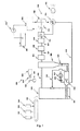
- the central part of the system according to the invention is the gas generator 100, which, as in CZ 293431 can be constructed described. He is supplied by a metering conveyor 101 with fuel. Above the metering conveyor 101, a sensor 102 for detecting the fuel structure (lumpy, coarse-grained, fine-grained) is provided, further a sensor 103 for detecting the fuel moisture and a sensor 104 for measuring the inductance (to detect metal parts).
- a cyclone 306 is connected, where solid substances (fly ash) are separated. These solid substances are fed via a chute 204 a fluidized bed gasifier 200.
- the fluid bed gasifier 200 is further supplied with ash from the gas generator 100 via a conveyor 201.
- This conveyor 201 may be formed as a screw, resulting in several advantages: the screw delivers metered, it seals and she crushes the ashes.
- the gases produced in the fluidized-bed gasifier 200 are supplied to the gas generator 100 via a pipeline 202. Since the ash does not normally contain much carbon, additional liquid fuel is injected into the fluidized-bed gasifier 200 via an injection pump 802 and a valve 803.
- the fluid bed gasifier 200 is supplied via an air supply 203 air, the resulting gas and the heated air then flow via the pipe 202 into the gas generator 100th
- an analyzer 300 is provided for the feedback. It consists of a pump 301, which sucks gas from the line 305 and pumps to a control burner 302. The light of the flame is decomposed by prism optics 304 and captured by an industrial color camera 303.
- the pyrolysis gas passes to a centrifugal filter 400 (eg of the type of decanter centrifuge, this is especially important when burning straw), from there via a line 501 to a gas scrubber 500 (Cl, S and NOx removed, particularly important in the Combustion of waste tires or sewage sludge), further via a line 601 to an absorption gas cooler 600 (cooled to about 25 ° C).
- a centrifugal filter 400 eg of the type of decanter centrifuge, this is especially important when burning straw
- a gas scrubber 500 Cl, S and NOx removed, particularly important in the Combustion of waste tires or sewage sludge
- an absorption gas cooler 600 cooled to about 25 ° C.
- the purified and cooled pyrolysis gas passes to a total of 700 designated turbo compressor system.
- it is mixed with air in a mixer 701.
- compressor 703 of the turbocharger into a diesel engine 800.
- the exhaust gases of the diesel engine 800 then drive the turbine 702 of the turbocharger, which in turn drives the compressor 703.
- the necessary combustion air is sucked in by an air blower 705 and fed via the air distribution 704 to the mixer 701.
- the air from the air distribution 704 is also supplied to the turbine 702 of the turbocharger to start the turbocharger.
- the system according to the invention works as follows:
- the air blower 705 and the conveyor 201 are turned on to discharge the ash.
- the air conveyed by the air blower 705 causes the turbine 702 to rotate, on the shaft of which is the compressor 703 which sucks the gas, whereby the necessary negative pressure is created at the outlet of the gas generator 100, so that air from the environment is sucked into the glow zone of the gas generator where the fuel is ignited.
- gas and heated air are formed, which are passed through the pipe 202 back into the gas generator 100.
- the generated gas then goes through the Cyclone 306, where it is freed from coarse dust, which deposits in the base and falls through the chute 204 in the fluidized bed gasifier 200.
- the fuel on the metering conveyor 101 is monitored by the sensors 102, 103, 104.
- Sensor 102 is a camera that detects fuel structure, size, amount, type and graininess.
- Sensor 103 is a humidity sensor and measures fuel moisture by contact measuring method.
- Sensor 104 is basically an inductance sensor and monitors that no metal objects and other non-combustible substances are entering the gas generator.
- pump 301 Connected to line 305 is pump 301, which sucks the gas and pushes it into the pilot burner 302, the flame of which is observed by camera 303 via prism optics 304 which breaks the light into the spectral lines. From this, the temperature of the gas and its composition is determined. The camera output is fed to the control computer, thereby realizing the feedback of the system.
- the gas passes after the cyclone 306 through the centrifugal filter 400, where it is freed from further solid impurities before entering the gas scrubber 500 connected by line 501. From the absorption filter, the gas is passed through the line 601 into the absorption gas cooler 600, after which it is supplied to the mixer 701 of the turbo-compressor system 700.
- the leached gas - freed of any undesirable impurities - is then forced into the engine 800 by the compressor 703.
- the ignition is ignited by injecting liquid fuel (eg methyl ester, bioethanol or benzene) by means of the injection pump 802 '.
- the resulting pyrolysis gas can also be burned in a thermal bath and thus used, for example. Warm water for central heating.
Landscapes
- Engineering & Computer Science (AREA)
- Mechanical Engineering (AREA)
- General Engineering & Computer Science (AREA)
- Chemical & Material Sciences (AREA)
- Combustion & Propulsion (AREA)
- Organic Chemistry (AREA)
- Oil, Petroleum & Natural Gas (AREA)
- Life Sciences & Earth Sciences (AREA)
- Environmental & Geological Engineering (AREA)
- Wood Science & Technology (AREA)
- Sustainable Development (AREA)
- Sustainable Energy (AREA)
- Gasification And Melting Of Waste (AREA)
- Processing Of Solid Wastes (AREA)
- Engine Equipment That Uses Special Cycles (AREA)
Applications Claiming Priority (1)
| Application Number | Priority Date | Filing Date | Title |
|---|---|---|---|
| AT0106805A AT502148A1 (de) | 2005-06-24 | 2005-06-24 | Anlage zur erzeugung von energie aus brennbarem abfall |
Publications (2)
| Publication Number | Publication Date |
|---|---|
| EP1746145A2 true EP1746145A2 (fr) | 2007-01-24 |
| EP1746145A3 EP1746145A3 (fr) | 2008-08-27 |
Family
ID=37027866
Family Applications (1)
| Application Number | Title | Priority Date | Filing Date |
|---|---|---|---|
| EP06116044A Withdrawn EP1746145A3 (fr) | 2005-06-24 | 2006-06-26 | Installation de production d'énergie à partir de déchets combustibles |
Country Status (2)
| Country | Link |
|---|---|
| EP (1) | EP1746145A3 (fr) |
| AT (1) | AT502148A1 (fr) |
Cited By (5)
| Publication number | Priority date | Publication date | Assignee | Title |
|---|---|---|---|---|
| WO2011121187A3 (fr) * | 2010-04-01 | 2012-08-02 | Upm-Kymmene Corporation | Procédé et système permettant de traiter un matériau qui contient une biomasse |
| EP2990464A1 (fr) * | 2013-07-11 | 2016-03-02 | Mitsubishi Heavy Industries Environmental & Chemical Engineering Co., Ltd. | Procédé permettant d'inhiber l'apparition de dépôt pyrolytique dans un système de gazéification par pyrolyse, et système de gazéification par pyrolyse |
| CN105674285A (zh) * | 2016-03-31 | 2016-06-15 | 彭本晨 | 一种新型生活垃圾气化炉 |
| CN108795505A (zh) * | 2018-06-29 | 2018-11-13 | 新奥科技发展有限公司 | 一种煤粉加氢气化方法及系统 |
| EP3259530B1 (fr) | 2015-02-19 | 2020-05-27 | Inray Oy | Système de commande pour la commande de l'alimentation d'un processus de combustion en combustible solide |
Families Citing this family (1)
| Publication number | Priority date | Publication date | Assignee | Title |
|---|---|---|---|---|
| DE102010031528B4 (de) * | 2010-07-19 | 2013-04-25 | Klaus Seeger | System zur Bestimmung eines Energiegehalts eines festen Brennstoffs und Verwendung des Systems |
Citations (3)
| Publication number | Priority date | Publication date | Assignee | Title |
|---|---|---|---|---|
| DE3744565A1 (de) * | 1986-12-30 | 1988-07-14 | Us Energy | Leistungserzeugungssystem und verfahren zur verwendung der hydropyrolyse |
| US5584255A (en) * | 1995-06-07 | 1996-12-17 | Proler Environmental Services, Inc. | Method and apparatus for gasifying organic materials and vitrifying residual ash |
| WO2000027952A1 (fr) * | 1998-11-11 | 2000-05-18 | Holderbank Financiere Glarus Ag | Procede de traitement de cendres de fond d'installations de combustion |
-
2005
- 2005-06-24 AT AT0106805A patent/AT502148A1/de not_active Application Discontinuation
-
2006
- 2006-06-26 EP EP06116044A patent/EP1746145A3/fr not_active Withdrawn
Patent Citations (3)
| Publication number | Priority date | Publication date | Assignee | Title |
|---|---|---|---|---|
| DE3744565A1 (de) * | 1986-12-30 | 1988-07-14 | Us Energy | Leistungserzeugungssystem und verfahren zur verwendung der hydropyrolyse |
| US5584255A (en) * | 1995-06-07 | 1996-12-17 | Proler Environmental Services, Inc. | Method and apparatus for gasifying organic materials and vitrifying residual ash |
| WO2000027952A1 (fr) * | 1998-11-11 | 2000-05-18 | Holderbank Financiere Glarus Ag | Procede de traitement de cendres de fond d'installations de combustion |
Cited By (11)
| Publication number | Priority date | Publication date | Assignee | Title |
|---|---|---|---|---|
| WO2011121187A3 (fr) * | 2010-04-01 | 2012-08-02 | Upm-Kymmene Corporation | Procédé et système permettant de traiter un matériau qui contient une biomasse |
| CN103038574A (zh) * | 2010-04-01 | 2013-04-10 | 芬欧汇川集团公司 | 加工含有生物量的材料的方法和系统 |
| RU2564309C2 (ru) * | 2010-04-01 | 2015-09-27 | Упм-Кюммене Корпорейшн | Способ и система для переработки материала, содержащего биомассу |
| CN103038574B (zh) * | 2010-04-01 | 2015-11-25 | 芬欧汇川集团公司 | 加工含有生物量的材料的方法和系统 |
| US9580246B2 (en) | 2010-04-01 | 2017-02-28 | Upm-Kymmene Corporation | Method and a system for processing material that contains biomass |
| EP2990464A1 (fr) * | 2013-07-11 | 2016-03-02 | Mitsubishi Heavy Industries Environmental & Chemical Engineering Co., Ltd. | Procédé permettant d'inhiber l'apparition de dépôt pyrolytique dans un système de gazéification par pyrolyse, et système de gazéification par pyrolyse |
| EP2990464A4 (fr) * | 2013-07-11 | 2016-05-18 | Mitsubishi Heavy Ind Environmental & Chemical Eng Co Ltd | Procédé permettant d'inhiber l'apparition de dépôt pyrolytique dans un système de gazéification par pyrolyse, et système de gazéification par pyrolyse |
| US10377952B2 (en) | 2013-07-11 | 2019-08-13 | Mitsubishi Heavy Industries Environmental & Chemical Engineering Co., Ltd. | Method for inhibiting occurrence of pyrolysis deposit in pyrolysis gasification system, and pyrolysis gasification system |
| EP3259530B1 (fr) | 2015-02-19 | 2020-05-27 | Inray Oy | Système de commande pour la commande de l'alimentation d'un processus de combustion en combustible solide |
| CN105674285A (zh) * | 2016-03-31 | 2016-06-15 | 彭本晨 | 一种新型生活垃圾气化炉 |
| CN108795505A (zh) * | 2018-06-29 | 2018-11-13 | 新奥科技发展有限公司 | 一种煤粉加氢气化方法及系统 |
Also Published As
| Publication number | Publication date |
|---|---|
| EP1746145A3 (fr) | 2008-08-27 |
| AT502148A1 (de) | 2007-01-15 |
Similar Documents
| Publication | Publication Date | Title |
|---|---|---|
| EP2545142B1 (fr) | Procédé et dispositif pour produire du gaz de synthèse et pour faire fonctionner un moteur à combustion interne au moyen de ce gaz | |
| DE102007005782B3 (de) | Verfahren und Anlage zur Trocknung von staubförmigen, insbesondere einer Vergasung zuzuführenden Brennstoffen | |
| CH615215A5 (fr) | ||
| EP0302310A1 (fr) | Procédé et dispositif pour l'élimination thermique de déchets | |
| EP1746145A2 (fr) | Installation de production d'énergie à partir de déchets combustibles | |
| EP2563881B1 (fr) | Procédé pour la gazéification de la biomasse | |
| DE102005045166B4 (de) | Verfahren zur Erzeugung thermischer Energie mit einem FLOX-Brenner | |
| DE4107200A1 (de) | Verfahren und anlage zur thermischen abfallbehandlung | |
| DE112011102289B4 (de) | Verringerter fossiler Brennstoff in einer Oxidationsanlage stromabwärts von einem Biomasseofen | |
| EP0155607A1 (fr) | Chaudière à gazéification de combustibles solides | |
| DE102008047201B4 (de) | Verfahren und Vorrichtung zur Produktion von Synthesegas und zum Betreiben eines Verbrennungsmotors damit | |
| DE19846805A1 (de) | Verfahren und Vorrichtung zur Vergasung und Verbrennung | |
| EP1377649B1 (fr) | Installation et procede pour produire de l'energie par pyrolyse | |
| EP1436366A1 (fr) | Procede pour produire du courant a partir d'un materiau carbone | |
| DE102006061583A1 (de) | Energiewandlungssystem für feste Biomasse und andere energetische, vergasbare Stoffe | |
| EP2522707B1 (fr) | Dispositif de génération d'un mélange de gaz combustible | |
| DD143712A3 (de) | Verfahren zur bereitstellung von prozessdampf in integrierten braunkohleveredlungsanlagen | |
| DE4425117C2 (de) | Verfahren zur Verbrennung von Klärschlamm in einem Wirbelschichtkessel | |
| DE102010049379A1 (de) | Vorrichtung zum energetischen Verwerten von festen organischen Abfällen | |
| DE102010005908B4 (de) | Verfahren zum Verbrennen von industriellem pflanzlichem Abfall, Vorrichtung zum Verbrennen von industriellem pflanzlichem Abfall und Boiler zur Dampferzeugung | |
| US20200200383A1 (en) | Non-polluting Biomass Waste Processor, Components and Processes for a Use by a Municipality, Industrial, Forestry and/or Agricultural Facility | |
| DE102014001785B4 (de) | Kleinstfeuerungsanlage für biogene Festbrennstoffe | |
| DE102010006263A1 (de) | Verfahren zur thermischen Verwertung von durch hydrothermale Karbonisierung hergestellte Brennstoffen, insbesondere Kohlestaub | |
| EP1852494A2 (fr) | Utilisation de la phase de glycérol générée lors de la production de biodiesel comme combustible | |
| DE2526947A1 (de) | Verfahren und vorrichtung zum herstellen von brenngas |
Legal Events
| Date | Code | Title | Description |
|---|---|---|---|
| PUAI | Public reference made under article 153(3) epc to a published international application that has entered the european phase |
Free format text: ORIGINAL CODE: 0009012 |
|
| AK | Designated contracting states |
Kind code of ref document: A2 Designated state(s): AT BE BG CH CY CZ DE DK EE ES FI FR GB GR HU IE IS IT LI LT LU LV MC NL PL PT RO SE SI SK TR |
|
| AX | Request for extension of the european patent |
Extension state: AL BA HR MK YU |
|
| PUAL | Search report despatched |
Free format text: ORIGINAL CODE: 0009013 |
|
| AK | Designated contracting states |
Kind code of ref document: A3 Designated state(s): AT BE BG CH CY CZ DE DK EE ES FI FR GB GR HU IE IS IT LI LT LU LV MC NL PL PT RO SE SI SK TR |
|
| AX | Request for extension of the european patent |
Extension state: AL BA HR MK RS |
|
| RIC1 | Information provided on ipc code assigned before grant |
Ipc: F23G 5/00 20060101ALI20080718BHEP Ipc: F23J 15/00 20060101ALI20080718BHEP Ipc: F23L 15/00 20060101ALI20080718BHEP Ipc: F23J 15/02 20060101ALI20080718BHEP Ipc: F23G 5/50 20060101ALI20080718BHEP Ipc: F23G 5/46 20060101ALI20080718BHEP Ipc: F23G 7/10 20060101ALI20080718BHEP Ipc: F23J 1/00 20060101ALI20080718BHEP Ipc: F23G 5/027 20060101ALI20080718BHEP Ipc: C10J 3/66 20060101ALI20080718BHEP Ipc: C10J 3/62 20060101ALI20080718BHEP Ipc: C10J 3/46 20060101AFI20061006BHEP |
|
| AKX | Designation fees paid | ||
| STAA | Information on the status of an ep patent application or granted ep patent |
Free format text: STATUS: THE APPLICATION IS DEEMED TO BE WITHDRAWN |
|
| REG | Reference to a national code |
Ref country code: DE Ref legal event code: 8566 |
|
| 18D | Application deemed to be withdrawn |
Effective date: 20090106 |