EP1746145A2 - Plant for the production of energy from combustible waste products - Google Patents
Plant for the production of energy from combustible waste products Download PDFInfo
- Publication number
- EP1746145A2 EP1746145A2 EP06116044A EP06116044A EP1746145A2 EP 1746145 A2 EP1746145 A2 EP 1746145A2 EP 06116044 A EP06116044 A EP 06116044A EP 06116044 A EP06116044 A EP 06116044A EP 1746145 A2 EP1746145 A2 EP 1746145A2
- Authority
- EP
- European Patent Office
- Prior art keywords
- gas
- fuel
- generator
- gas generator
- plant
- Prior art date
- Legal status (The legal status is an assumption and is not a legal conclusion. Google has not performed a legal analysis and makes no representation as to the accuracy of the status listed.)
- Withdrawn
Links
Images
Classifications
-
- C—CHEMISTRY; METALLURGY
- C10—PETROLEUM, GAS OR COKE INDUSTRIES; TECHNICAL GASES CONTAINING CARBON MONOXIDE; FUELS; LUBRICANTS; PEAT
- C10J—PRODUCTION OF PRODUCER GAS, WATER-GAS, SYNTHESIS GAS FROM SOLID CARBONACEOUS MATERIAL, OR MIXTURES CONTAINING THESE GASES; CARBURETTING AIR OR OTHER GASES
- C10J3/00—Production of combustible gases containing carbon monoxide from solid carbonaceous fuels
- C10J3/46—Gasification of granular or pulverulent flues in suspension
- C10J3/54—Gasification of granular or pulverulent fuels by the Winkler technique, i.e. by fluidisation
- C10J3/56—Apparatus; Plants
-
- C—CHEMISTRY; METALLURGY
- C10—PETROLEUM, GAS OR COKE INDUSTRIES; TECHNICAL GASES CONTAINING CARBON MONOXIDE; FUELS; LUBRICANTS; PEAT
- C10J—PRODUCTION OF PRODUCER GAS, WATER-GAS, SYNTHESIS GAS FROM SOLID CARBONACEOUS MATERIAL, OR MIXTURES CONTAINING THESE GASES; CARBURETTING AIR OR OTHER GASES
- C10J3/00—Production of combustible gases containing carbon monoxide from solid carbonaceous fuels
- C10J3/72—Other features
- C10J3/723—Controlling or regulating the gasification process
-
- F—MECHANICAL ENGINEERING; LIGHTING; HEATING; WEAPONS; BLASTING
- F23—COMBUSTION APPARATUS; COMBUSTION PROCESSES
- F23G—CREMATION FURNACES; CONSUMING WASTE PRODUCTS BY COMBUSTION
- F23G5/00—Incineration of waste; Incinerator constructions; Details, accessories or control therefor
- F23G5/006—General arrangement of incineration plant, e.g. flow sheets
-
- F—MECHANICAL ENGINEERING; LIGHTING; HEATING; WEAPONS; BLASTING
- F23—COMBUSTION APPARATUS; COMBUSTION PROCESSES
- F23G—CREMATION FURNACES; CONSUMING WASTE PRODUCTS BY COMBUSTION
- F23G5/00—Incineration of waste; Incinerator constructions; Details, accessories or control therefor
- F23G5/02—Incineration of waste; Incinerator constructions; Details, accessories or control therefor with pretreatment
- F23G5/027—Incineration of waste; Incinerator constructions; Details, accessories or control therefor with pretreatment pyrolising or gasifying stage
- F23G5/0276—Incineration of waste; Incinerator constructions; Details, accessories or control therefor with pretreatment pyrolising or gasifying stage using direct heating
-
- F—MECHANICAL ENGINEERING; LIGHTING; HEATING; WEAPONS; BLASTING
- F23—COMBUSTION APPARATUS; COMBUSTION PROCESSES
- F23G—CREMATION FURNACES; CONSUMING WASTE PRODUCTS BY COMBUSTION
- F23G5/00—Incineration of waste; Incinerator constructions; Details, accessories or control therefor
- F23G5/44—Details; Accessories
- F23G5/46—Recuperation of heat
-
- F—MECHANICAL ENGINEERING; LIGHTING; HEATING; WEAPONS; BLASTING
- F23—COMBUSTION APPARATUS; COMBUSTION PROCESSES
- F23G—CREMATION FURNACES; CONSUMING WASTE PRODUCTS BY COMBUSTION
- F23G5/00—Incineration of waste; Incinerator constructions; Details, accessories or control therefor
- F23G5/50—Control or safety arrangements
-
- F—MECHANICAL ENGINEERING; LIGHTING; HEATING; WEAPONS; BLASTING
- F23—COMBUSTION APPARATUS; COMBUSTION PROCESSES
- F23G—CREMATION FURNACES; CONSUMING WASTE PRODUCTS BY COMBUSTION
- F23G7/00—Incinerators or other apparatus for consuming industrial waste, e.g. chemicals
- F23G7/10—Incinerators or other apparatus for consuming industrial waste, e.g. chemicals of field or garden waste or biomasses
- F23G7/105—Incinerators or other apparatus for consuming industrial waste, e.g. chemicals of field or garden waste or biomasses of wood waste
-
- F—MECHANICAL ENGINEERING; LIGHTING; HEATING; WEAPONS; BLASTING
- F23—COMBUSTION APPARATUS; COMBUSTION PROCESSES
- F23J—REMOVAL OR TREATMENT OF COMBUSTION PRODUCTS OR COMBUSTION RESIDUES; FLUES
- F23J1/00—Removing ash, clinker, or slag from combustion chambers
-
- F—MECHANICAL ENGINEERING; LIGHTING; HEATING; WEAPONS; BLASTING
- F23—COMBUSTION APPARATUS; COMBUSTION PROCESSES
- F23J—REMOVAL OR TREATMENT OF COMBUSTION PRODUCTS OR COMBUSTION RESIDUES; FLUES
- F23J15/00—Arrangements of devices for treating smoke or fumes
- F23J15/006—Layout of treatment plant
-
- F—MECHANICAL ENGINEERING; LIGHTING; HEATING; WEAPONS; BLASTING
- F23—COMBUSTION APPARATUS; COMBUSTION PROCESSES
- F23J—REMOVAL OR TREATMENT OF COMBUSTION PRODUCTS OR COMBUSTION RESIDUES; FLUES
- F23J15/00—Arrangements of devices for treating smoke or fumes
- F23J15/02—Arrangements of devices for treating smoke or fumes of purifiers, e.g. for removing noxious material
- F23J15/022—Arrangements of devices for treating smoke or fumes of purifiers, e.g. for removing noxious material for removing solid particulate material from the gasflow
- F23J15/027—Arrangements of devices for treating smoke or fumes of purifiers, e.g. for removing noxious material for removing solid particulate material from the gasflow using cyclone separators
-
- F—MECHANICAL ENGINEERING; LIGHTING; HEATING; WEAPONS; BLASTING
- F23—COMBUSTION APPARATUS; COMBUSTION PROCESSES
- F23L—SUPPLYING AIR OR NON-COMBUSTIBLE LIQUIDS OR GASES TO COMBUSTION APPARATUS IN GENERAL ; VALVES OR DAMPERS SPECIALLY ADAPTED FOR CONTROLLING AIR SUPPLY OR DRAUGHT IN COMBUSTION APPARATUS; INDUCING DRAUGHT IN COMBUSTION APPARATUS; TOPS FOR CHIMNEYS OR VENTILATING SHAFTS; TERMINALS FOR FLUES
- F23L15/00—Heating of air supplied for combustion
-
- C—CHEMISTRY; METALLURGY
- C10—PETROLEUM, GAS OR COKE INDUSTRIES; TECHNICAL GASES CONTAINING CARBON MONOXIDE; FUELS; LUBRICANTS; PEAT
- C10J—PRODUCTION OF PRODUCER GAS, WATER-GAS, SYNTHESIS GAS FROM SOLID CARBONACEOUS MATERIAL, OR MIXTURES CONTAINING THESE GASES; CARBURETTING AIR OR OTHER GASES
- C10J2300/00—Details of gasification processes
- C10J2300/09—Details of the feed, e.g. feeding of spent catalyst, inert gas or halogens
- C10J2300/0913—Carbonaceous raw material
- C10J2300/0946—Waste, e.g. MSW, tires, glass, tar sand, peat, paper, lignite, oil shale
-
- C—CHEMISTRY; METALLURGY
- C10—PETROLEUM, GAS OR COKE INDUSTRIES; TECHNICAL GASES CONTAINING CARBON MONOXIDE; FUELS; LUBRICANTS; PEAT
- C10J—PRODUCTION OF PRODUCER GAS, WATER-GAS, SYNTHESIS GAS FROM SOLID CARBONACEOUS MATERIAL, OR MIXTURES CONTAINING THESE GASES; CARBURETTING AIR OR OTHER GASES
- C10J2300/00—Details of gasification processes
- C10J2300/09—Details of the feed, e.g. feeding of spent catalyst, inert gas or halogens
- C10J2300/0983—Additives
- C10J2300/0989—Hydrocarbons as additives to gasifying agents to improve caloric properties
-
- C—CHEMISTRY; METALLURGY
- C10—PETROLEUM, GAS OR COKE INDUSTRIES; TECHNICAL GASES CONTAINING CARBON MONOXIDE; FUELS; LUBRICANTS; PEAT
- C10J—PRODUCTION OF PRODUCER GAS, WATER-GAS, SYNTHESIS GAS FROM SOLID CARBONACEOUS MATERIAL, OR MIXTURES CONTAINING THESE GASES; CARBURETTING AIR OR OTHER GASES
- C10J2300/00—Details of gasification processes
- C10J2300/16—Integration of gasification processes with another plant or parts within the plant
- C10J2300/164—Integration of gasification processes with another plant or parts within the plant with conversion of synthesis gas
- C10J2300/1643—Conversion of synthesis gas to energy
- C10J2300/165—Conversion of synthesis gas to energy integrated with a gas turbine or gas motor
-
- F—MECHANICAL ENGINEERING; LIGHTING; HEATING; WEAPONS; BLASTING
- F23—COMBUSTION APPARATUS; COMBUSTION PROCESSES
- F23G—CREMATION FURNACES; CONSUMING WASTE PRODUCTS BY COMBUSTION
- F23G2201/00—Pretreatment
- F23G2201/30—Pyrolysing
- F23G2201/304—Burning pyrosolids
-
- F—MECHANICAL ENGINEERING; LIGHTING; HEATING; WEAPONS; BLASTING
- F23—COMBUSTION APPARATUS; COMBUSTION PROCESSES
- F23G—CREMATION FURNACES; CONSUMING WASTE PRODUCTS BY COMBUSTION
- F23G2201/00—Pretreatment
- F23G2201/40—Gasification
-
- F—MECHANICAL ENGINEERING; LIGHTING; HEATING; WEAPONS; BLASTING
- F23—COMBUSTION APPARATUS; COMBUSTION PROCESSES
- F23G—CREMATION FURNACES; CONSUMING WASTE PRODUCTS BY COMBUSTION
- F23G2206/00—Waste heat recuperation
- F23G2206/20—Waste heat recuperation using the heat in association with another installation
- F23G2206/202—Waste heat recuperation using the heat in association with another installation with an internal combustion engine
-
- F—MECHANICAL ENGINEERING; LIGHTING; HEATING; WEAPONS; BLASTING
- F23—COMBUSTION APPARATUS; COMBUSTION PROCESSES
- F23G—CREMATION FURNACES; CONSUMING WASTE PRODUCTS BY COMBUSTION
- F23G2209/00—Specific waste
- F23G2209/12—Sludge, slurries or mixtures of liquids
-
- F—MECHANICAL ENGINEERING; LIGHTING; HEATING; WEAPONS; BLASTING
- F23—COMBUSTION APPARATUS; COMBUSTION PROCESSES
- F23G—CREMATION FURNACES; CONSUMING WASTE PRODUCTS BY COMBUSTION
- F23G2209/00—Specific waste
- F23G2209/28—Plastics or rubber like materials
- F23G2209/281—Tyres
-
- F—MECHANICAL ENGINEERING; LIGHTING; HEATING; WEAPONS; BLASTING
- F23—COMBUSTION APPARATUS; COMBUSTION PROCESSES
- F23J—REMOVAL OR TREATMENT OF COMBUSTION PRODUCTS OR COMBUSTION RESIDUES; FLUES
- F23J2900/00—Special arrangements for conducting or purifying combustion fumes; Treatment of fumes or ashes
- F23J2900/01007—Thermal treatments of ash, e.g. temper or shock-cooling for granulation
-
- Y—GENERAL TAGGING OF NEW TECHNOLOGICAL DEVELOPMENTS; GENERAL TAGGING OF CROSS-SECTIONAL TECHNOLOGIES SPANNING OVER SEVERAL SECTIONS OF THE IPC; TECHNICAL SUBJECTS COVERED BY FORMER USPC CROSS-REFERENCE ART COLLECTIONS [XRACs] AND DIGESTS
- Y02—TECHNOLOGIES OR APPLICATIONS FOR MITIGATION OR ADAPTATION AGAINST CLIMATE CHANGE
- Y02E—REDUCTION OF GREENHOUSE GAS [GHG] EMISSIONS, RELATED TO ENERGY GENERATION, TRANSMISSION OR DISTRIBUTION
- Y02E20/00—Combustion technologies with mitigation potential
- Y02E20/12—Heat utilisation in combustion or incineration of waste
-
- Y—GENERAL TAGGING OF NEW TECHNOLOGICAL DEVELOPMENTS; GENERAL TAGGING OF CROSS-SECTIONAL TECHNOLOGIES SPANNING OVER SEVERAL SECTIONS OF THE IPC; TECHNICAL SUBJECTS COVERED BY FORMER USPC CROSS-REFERENCE ART COLLECTIONS [XRACs] AND DIGESTS
- Y02—TECHNOLOGIES OR APPLICATIONS FOR MITIGATION OR ADAPTATION AGAINST CLIMATE CHANGE
- Y02E—REDUCTION OF GREENHOUSE GAS [GHG] EMISSIONS, RELATED TO ENERGY GENERATION, TRANSMISSION OR DISTRIBUTION
- Y02E20/00—Combustion technologies with mitigation potential
- Y02E20/34—Indirect CO2mitigation, i.e. by acting on non CO2directly related matters of the process, e.g. pre-heating or heat recovery
-
- Y—GENERAL TAGGING OF NEW TECHNOLOGICAL DEVELOPMENTS; GENERAL TAGGING OF CROSS-SECTIONAL TECHNOLOGIES SPANNING OVER SEVERAL SECTIONS OF THE IPC; TECHNICAL SUBJECTS COVERED BY FORMER USPC CROSS-REFERENCE ART COLLECTIONS [XRACs] AND DIGESTS
- Y02—TECHNOLOGIES OR APPLICATIONS FOR MITIGATION OR ADAPTATION AGAINST CLIMATE CHANGE
- Y02E—REDUCTION OF GREENHOUSE GAS [GHG] EMISSIONS, RELATED TO ENERGY GENERATION, TRANSMISSION OR DISTRIBUTION
- Y02E50/00—Technologies for the production of fuel of non-fossil origin
- Y02E50/30—Fuel from waste, e.g. synthetic alcohol or diesel
Definitions
- the present invention relates to a system for generating energy, in particular of electrical energy and heat energy, of combustible waste, in particular of organic origin, wherein the system includes an automatic ash removal gas generator and a cyclone, wherein preferably a motor is provided, which is provided with the Gas generator is operated gas and drives a generator for generating electricity.
- the known plants have many disadvantages: they can burn with them only quality fuel effectively, up to a water content of 18% by mass; Gasification produces liquid waste containing hydrocarbons, in particular phenol, which must be disposed of accordingly, usually in sewage treatment plants. It is not a waste-free technology.
- the heat output can be changed only to a small extent, and only by about 25% of the rated heat output.
- the cleanliness of the pyrolysis gas depends on the system load (heat output) and the water content in the fuel. It follows that the pyrolysis gas produced in the known generators can not be used for the large-scale supply of households with electricity, heating and hot water.
- a plant of the type mentioned is from the CZ 293431 known. With this plant, a more efficient gasification of organic waste is possible, which enables the effective utilization of forest, wood and other combustible agricultural waste. Lower emissions are achieved, so that the environment is less polluted.
- the pyrolysis gas produced has a consistently high quality, especially as regards the maintenance of the calorific value and the cleanliness of the gas.
- the increased carbon content in the ashes in combustion of highly comminuted fuel with different moisture, but also in the combustion of sewage sludge or car tires, effectively used for heat production in the gasification process by the fluidized bed gasifier is connected with subsequent heating of the air parallel to the gas generator, wherein the heated air is fed back into the gas generator.
- the problem of disposing of larger amounts of ash which would have to be disposed of in the known system in the case of the incineration of sewage sludge or car tires as hazardous waste unnecessary.
- the essence of the invention is that a fluidized bed gasifier is provided, which gasifies mainly carbon from ashes of biomass from cleaning sludge, straw chippings, grain crop and pulp, the gas or the heated air is fed back into the gas generator, where or she then participates in the cracking process.
- sensors are installed over a metering conveyor for the fuel, eg for measuring moisture, structure, granularity and composition of the fuel.
- the information is transferred to the control computer.
- the system should be run at lower power if the fuel is particularly humid or very fine. This can be detected in good time by the sensors (feedforward control).
- foreign objects eg metals or stones
- an analyzer e.g. a flame spectrometer to provide for the pyrolysis gas developed.
- a flame spectrometer e.g. Detect contamination by phenols and minimize by appropriate regulation.
- the gas composition may be by spectral decomposition of the flame of a pilot burner which sucks gas from the pipeline in front of or behind the cyclone with a pump and burns while a camera is picking up the flame.
- the control works so that with poor fuel (eg high humidity) or too much tar in the pyrolysis gas, the engine power is reduced or more fuel is added, causing the temperature in the reactor to rise, raising the quality of the pyrolysis gas becomes. If more fuel is added, although the ash increase, but this makes the system of the invention nothing, because the ash is recycled in the fluidized bed gasifier. It is therefore possible to produce constant amounts of pyrolysis gas even with fluctuating fuel quality.
- poor fuel eg high humidity
- tar e.g high humidity
- the gas is freed in a centrifugal filter of fine solid impurities and condensate.
- a downstream gas scrubber the gas is mainly freed from sulfur and chlorine.
- the pyrolysis gas is cooled in an absorption gas cooler.
- the efficiency of the system is increased because the resulting heat can, for. be used as district heating.
- it is provided to mix the cleaned and cooled pyrolysis gas in a mixer with air and to press via a compressor of an exhaust gas turbocharger system in a diesel engine, which is ignited by injection of liquid fuel.
- the system according to the invention thus not only allows to use turbocharger gasoline engines, but also diesel engines are usable, the ignition by injection of liquid Fuel, preferably from biofuel, is effected.
- the central part of the system according to the invention is the gas generator 100, which, as in CZ 293431 can be constructed described. He is supplied by a metering conveyor 101 with fuel. Above the metering conveyor 101, a sensor 102 for detecting the fuel structure (lumpy, coarse-grained, fine-grained) is provided, further a sensor 103 for detecting the fuel moisture and a sensor 104 for measuring the inductance (to detect metal parts).
- a cyclone 306 is connected, where solid substances (fly ash) are separated. These solid substances are fed via a chute 204 a fluidized bed gasifier 200.
- the fluid bed gasifier 200 is further supplied with ash from the gas generator 100 via a conveyor 201.
- This conveyor 201 may be formed as a screw, resulting in several advantages: the screw delivers metered, it seals and she crushes the ashes.
- the gases produced in the fluidized-bed gasifier 200 are supplied to the gas generator 100 via a pipeline 202. Since the ash does not normally contain much carbon, additional liquid fuel is injected into the fluidized-bed gasifier 200 via an injection pump 802 and a valve 803.
- the fluid bed gasifier 200 is supplied via an air supply 203 air, the resulting gas and the heated air then flow via the pipe 202 into the gas generator 100th
- an analyzer 300 is provided for the feedback. It consists of a pump 301, which sucks gas from the line 305 and pumps to a control burner 302. The light of the flame is decomposed by prism optics 304 and captured by an industrial color camera 303.
- the pyrolysis gas passes to a centrifugal filter 400 (eg of the type of decanter centrifuge, this is especially important when burning straw), from there via a line 501 to a gas scrubber 500 (Cl, S and NOx removed, particularly important in the Combustion of waste tires or sewage sludge), further via a line 601 to an absorption gas cooler 600 (cooled to about 25 ° C).
- a centrifugal filter 400 eg of the type of decanter centrifuge, this is especially important when burning straw
- a gas scrubber 500 Cl, S and NOx removed, particularly important in the Combustion of waste tires or sewage sludge
- an absorption gas cooler 600 cooled to about 25 ° C.
- the purified and cooled pyrolysis gas passes to a total of 700 designated turbo compressor system.
- it is mixed with air in a mixer 701.
- compressor 703 of the turbocharger into a diesel engine 800.
- the exhaust gases of the diesel engine 800 then drive the turbine 702 of the turbocharger, which in turn drives the compressor 703.
- the necessary combustion air is sucked in by an air blower 705 and fed via the air distribution 704 to the mixer 701.
- the air from the air distribution 704 is also supplied to the turbine 702 of the turbocharger to start the turbocharger.
- the system according to the invention works as follows:
- the air blower 705 and the conveyor 201 are turned on to discharge the ash.
- the air conveyed by the air blower 705 causes the turbine 702 to rotate, on the shaft of which is the compressor 703 which sucks the gas, whereby the necessary negative pressure is created at the outlet of the gas generator 100, so that air from the environment is sucked into the glow zone of the gas generator where the fuel is ignited.
- gas and heated air are formed, which are passed through the pipe 202 back into the gas generator 100.
- the generated gas then goes through the Cyclone 306, where it is freed from coarse dust, which deposits in the base and falls through the chute 204 in the fluidized bed gasifier 200.
- the fuel on the metering conveyor 101 is monitored by the sensors 102, 103, 104.
- Sensor 102 is a camera that detects fuel structure, size, amount, type and graininess.
- Sensor 103 is a humidity sensor and measures fuel moisture by contact measuring method.
- Sensor 104 is basically an inductance sensor and monitors that no metal objects and other non-combustible substances are entering the gas generator.
- pump 301 Connected to line 305 is pump 301, which sucks the gas and pushes it into the pilot burner 302, the flame of which is observed by camera 303 via prism optics 304 which breaks the light into the spectral lines. From this, the temperature of the gas and its composition is determined. The camera output is fed to the control computer, thereby realizing the feedback of the system.
- the gas passes after the cyclone 306 through the centrifugal filter 400, where it is freed from further solid impurities before entering the gas scrubber 500 connected by line 501. From the absorption filter, the gas is passed through the line 601 into the absorption gas cooler 600, after which it is supplied to the mixer 701 of the turbo-compressor system 700.
- the leached gas - freed of any undesirable impurities - is then forced into the engine 800 by the compressor 703.
- the ignition is ignited by injecting liquid fuel (eg methyl ester, bioethanol or benzene) by means of the injection pump 802 '.
- the resulting pyrolysis gas can also be burned in a thermal bath and thus used, for example. Warm water for central heating.
Abstract
Description
Die vorliegende Erfindung betrifft eine Anlage zur Erzeugung von Energie, insbesondere von elektrischer Energie und Wärmeenergie, aus brennbarem Abfall, insbesondere organischer Herkunft, wobei die Anlage einen Gasgenerator mit automatischer Entaschung und einen Zyklon beinhaltet, wobei vorzugsweise ein Motor vorgesehen ist, der mit dem im Gasgenerator erzeugten Gas betrieben wird und einen Generator zur Stromerzeugung antreibt.The present invention relates to a system for generating energy, in particular of electrical energy and heat energy, of combustible waste, in particular of organic origin, wherein the system includes an automatic ash removal gas generator and a cyclone, wherein preferably a motor is provided, which is provided with the Gas generator is operated gas and drives a generator for generating electricity.
Die Vergasung von Holzmasse zur Erzeugung von Gas als Brennstoff ist bekannt. Dieses Gas, als Pyrolysegas bezeichnet, wurde besonders in den Zwanziger- bis Vierzigerjahren des vorigen Jahrhunderts als Brennstoff für modifizierte Diesel- und Benzinmotore verwendet. Als Holzmasse wurde zu diesem Zweck Buchen- und Eichenholz verwendet, mit Wassergehalt bis 18 Masse-%, in Holzschnitzel mit bestimmten Maßen zerkleinert. Dadurch gelang es, die Verschmutzung des Pyrolysegases durch Flüssigkeiten, insbesondere durch Teer und Phenol, zu reduzieren. Trotzdem war dieser Anteil an Teer und Phenol immer noch erheblich, wodurch nicht nur die Motore verunreinigt und die Ventile verstopft wurden, sondern vor allem auch die Umwelt belastet wurde, weil diese flüssigen Verunreinigungen einfach in der Umwelt freigesetzt wurden.The gasification of wood pulp for the production of gas as fuel is known. This gas, called pyrolysis gas, was used as fuel for modified diesel and gasoline engines, especially in the twenties to the forties of the last century. For this purpose beech and oak wood was used as the wood mass, with a water content of up to 18% by mass, crushed into wood chips of certain dimensions. This made it possible to reduce the pollution of the pyrolysis gas by liquids, in particular by tar and phenol. Nevertheless, this proportion of tar and phenol was still significant, which not only contaminated the engines and clogged the valves, but also polluted the environment because these liquid contaminants were simply released into the environment.
Später kam es zu einem Mangel an hartem Holz, vor allem an Eichen- und Buchenholz. Außerdem entstand ein Bedarf, nicht nur die wesentliche Menge an hartem Agrarabfall zu verarbeiten, sondern auch den Abfall aus der Holzproduktion, wo vor allem Weichholz verwendet wurde. Dieses Weichholz, insbesondere aus Nadelbäumen, Pappeln u.a., beinhaltet durchschnittlich ca. 30 Masse-% Wasser, was den Vergasungsprozess in den bekannten Vergasungsanlagen wesentlich erschwert. Die Vergasung von feuchtem Holzabfall aus Weichholz und auch seine Verbrennung in Kesselräumen hat einen ungünstigen Einfluss auf die Umwelt, weil sich in den Rauchgasen unerwünscht hohe Mengen an Stickoxiden befinden, und es entsteht auch eine größere Menge von Abfallwasser, in dem sich Kohlenwasserstoffe befinden, vor allem Phenol.Later there was a lack of hard wood, especially oak and beech wood. In addition, there was a need to process not only the substantial amount of hard agricultural waste, but also the waste from wood production, where mainly softwood was used. This softwood, in particular from conifers, poplars and others, contains on average about 30% by mass of water, which makes the gasification process in the known gasification plants considerably more difficult. The gasification of moist wood waste from softwood and its combustion in boiler rooms has an adverse effect on the environment, because in the flue gases are undesirably high levels of nitrogen oxides, and There is also a greater amount of waste water containing hydrocarbons, especially phenol.
Die Verbrennung von Agrarabfällen, z. B. Stroh, ist für die Wärmeproduktion sehr ungünstig, sowohl aus energetischer als auch aus ökologischer Sicht. Solch eine Verbrennung erfordert eine nachfolgende Reinigung der Emissionen, die Phenol enthalten.The incineration of agricultural waste, z. As straw, is very unfavorable for the heat production, both from an energetic and ecological point of view. Such combustion requires subsequent purification of the emissions containing phenol.
Die günstigere Verwertung von Agrarabfall für energetische Zwecke ist die Vergasung dieser Abfälle und nachfolgend die Verbrennung des entstehenden Pyrolysegases, z.B. in einem Brennersystem. Das ermöglicht es, Erdgas ganz oder teilweise durch das Pyrolysegas zu ersetzen.The cheaper use of agricultural waste for energy purposes is the gasification of this waste and subsequently the combustion of the resulting pyrolysis gas, e.g. in a burner system. This makes it possible to replace all or part of natural gas by the pyrolysis gas.
Die bekannten Anlagen weisen zahlreiche Nachteile auf: man kann mit ihnen nur Qualitätsbrennstoff effektiv verbrennen, bis zu einem Wassergehalt von 18 Masse-%; bei der Vergasung entsteht flüssiger Abfall, der Kohlenwasserstoffe, insbesondere Phenol, beinhaltet, der in der Folge entsprechend entsorgt werden muss, in der Regel in Kläranlagen. Es handelt sich also nicht um eine abfalllose Technologie.The known plants have many disadvantages: they can burn with them only quality fuel effectively, up to a water content of 18% by mass; Gasification produces liquid waste containing hydrocarbons, in particular phenol, which must be disposed of accordingly, usually in sewage treatment plants. It is not a waste-free technology.
Die Wärmeleistung kann nur in kleinem Umfang verändert werden, und zwar nur um etwa 25% der Nennwärmeleistung. Die Sauberkeit des Pyrolysegases ist von der Anlagebelastung (Wärmeleistung) und vom Wassergehalt im Brennstoff abhängig. Daraus ergibt sich, dass das in den bekannten Generatoren erzeugte Pyrolysegas nicht für die großflächige Versorgung von Haushalten mit Strom, Heizung und Warmwasser verwendet werden kann.The heat output can be changed only to a small extent, and only by about 25% of the rated heat output. The cleanliness of the pyrolysis gas depends on the system load (heat output) and the water content in the fuel. It follows that the pyrolysis gas produced in the known generators can not be used for the large-scale supply of households with electricity, heating and hot water.
Eine Anlage der eingangs genannten Art ist aus der
Mit dieser Anlage ist es möglich, Wald- und Holzabfall mit einer Feuchtigkeit bis zu 20 Masse-% zu verwerten, ohne dabei die vorgegebenen niedrigen Ausgangsemissionen zu überschreiten oder die Qualität des Pyrolysegases zu verringern. Mit dem Pyrolysegas dieser Anlage kann man daher vorteilhafterweise Verbrennungsmotoren (Ottomotoren) speisen und mit diesen einen Generator antreiben.With this plant, it is possible to recycle forest and wood waste with a moisture content of up to 20% by mass, without losing the exceed specified low output emissions or reduce the quality of the pyrolysis gas. With the pyrolysis gas of this system can therefore advantageously feed combustion engines (gasoline engines) and drive a generator with them.
Die Erfahrungen beim Betrieb mehrerer Prototypen zeigten, dass diese Vorgaben tatsächlich erfüllt werden können. Es zeigten sich aber auch die folgenden Mängel:The experience of operating several prototypes showed that these specifications can actually be met. But there were also the following shortcomings:
Es ist in der Praxis schwierig, die notwendige Holzmasse mit der benötigten Struktur für einen Ganzjahresbetrieb zu vernünftigen Preisen aufzutreiben.It is difficult in practice to raise the necessary wood mass with the required structure for a year-round operation at reasonable prices.
Es wäre günstig, auch grünes Hackgut, Stroh und auch Körnerfrüchte verwerten zu können. Derartiger Brennstoff steht in viel größerer Menge zur Verfügung. Der Brennstoff enthält dann viel kleines Korn, aber auch Stücke von der Größe groben Hackguts, vor allem aber hat er stark schwankenden Wassergehalt.It would be beneficial to be able to use green wood chips, straw and grains. Such fuel is available in much larger quantities. The fuel then contains a lot of small grain, but also pieces the size of coarse wood chips, but above all, it has strongly fluctuating water content.
Solcher Brennstoff mit unterschiedlicher Korngröße, vor allem organischer Herkunft, und verschiedener Feuchtigkeit verursacht in der bekannten Anlage jedoch einen erhöhten Kohlenstoffdurchfall in die Asche und dadurch wesentlich mehr festen Abfall. (Holz in größeren Stücken ergibt nur sehr wenig Asche, ca. 1/2 %, aber gehäckseltes Holz kann bis zu 5% festen Abfall erzeugen, der dann im Zyklon abgeschieden wird.) Außerdem bewirkt die ungleiche Feuchtigkeit des Brennstoffs eine Möglichkeit zur Bildung einer größeren Teermenge, die nicht auf verbrennbare Kohlenwasserstoffe abgebaut werden kann und starke Motorverschmutzung verursacht. Der erreichte Wirkungsgrad der Übertragung von Wärmeenergie in elektrische Energie beträgt bei diesen Anlagen ca. 27%.Such fuel with different particle size, especially of organic origin, and different moisture caused in the known system, however, an increased carbon diarrhea into the ash and thus significantly more solid waste. (Wood in larger pieces gives very little ash, about 1/2%, but chipped wood can produce up to 5% solid waste, which is then deposited in the cyclone.) In addition, the uneven moisture of the fuel creates a possibility for the formation of a larger amount of tar, which can not be degraded to combustible hydrocarbons and causes severe engine fouling. The achieved efficiency of the transfer of thermal energy into electrical energy is about 27% for these systems.
Es ist Aufgabe der vorliegenden Erfindung, eine Anlage der eingangs genannten Art so zu verbessern, dass auch Brennstoffe geringerer Qualität, insbesondere mit höherer Feuchtigkeit, verwertet werden können, ohne die Qualität des Pyrolysegases oder den Wirkungsgrad zu verschlechtern. Sogar Stroh, Autoreifen oder Klärschlamm sollen verwertet werden können. Weiters soll der Wirkungsgrad höher sein, anzustreben wären 33%.It is an object of the present invention to improve a plant of the type mentioned in such a way that fuels of lower quality, in particular with higher moisture, can be utilized, without the quality of the pyrolysis gas or the efficiency deteriorate. Even straw, car tires or sewage sludge should be able to be recycled. Furthermore, the efficiency should be higher, to aim at 33%.
Diese Aufgaben werden durch eine Anlage der eingangs genannten Art erfindungsgemäß dadurch gelöst, dass die Asche im Gasgenerator und die im Zyklon abgeschiedenen Feststoffe einem Fließbettvergaser zugeführt werden, dessen Abgase in den Gasgenerator zurückgeführt werden.These objects are achieved by a plant of the type mentioned in the present invention that the ash in the gas generator and the separated solids in the cyclone are fed to a fluidized bed gasifier, the exhaust gases are returned to the gas generator.
Erfindungsgemäß wird also der erhöhte Kohlenstoffanteil in der Asche bei Verbrennung stark zerkleinerten Brennstoffs mit unterschiedlicher Feuchtigkeit, aber auch bei Verbrennung von Klärschlamm oder Autoreifen, effektiv zur Wärmeproduktion beim Vergasungsprozess verwendet, indem der Fließbettvergaser mit nachfolgender Erwärmung der Luft parallel zum Gasgenerator angeschlossen wird, wobei die erwärmte Luft zurück in den Gasgenerator geführt wird. Auf diese Weise erübrigt sich auch die Problematik der Entsorgung größerer Mengen an Asche, die bei der bekannten Anlage im Falle der Verbrennung von Klärschlamm oder Autoreifen als Sondermüll entsorgt werden müsste.According to the invention, therefore, the increased carbon content in the ashes in combustion of highly comminuted fuel with different moisture, but also in the combustion of sewage sludge or car tires, effectively used for heat production in the gasification process by the fluidized bed gasifier is connected with subsequent heating of the air parallel to the gas generator, wherein the heated air is fed back into the gas generator. In this way, the problem of disposing of larger amounts of ash, which would have to be disposed of in the known system in the case of the incineration of sewage sludge or car tires as hazardous waste unnecessary.
Das Wesentliche der Erfindung besteht darin, dass ein Fließbettvergaser vorgesehen ist, welcher vor allem Kohlenstoff aus Aschen von Biomasse aus Reinigungsschlamm, Strohsplitt, Körnerfrucht und Papiermasse vergast, wobei das Gas bzw. die erwärmte Luft zurück in den Gasgenerator geführt wird, wo es bzw. sie dann am Krackverfahren teilnimmt.The essence of the invention is that a fluidized bed gasifier is provided, which gasifies mainly carbon from ashes of biomass from cleaning sludge, straw chippings, grain crop and pulp, the gas or the heated air is fed back into the gas generator, where or she then participates in the cracking process.
Vorzugsweise sind über einem Dosierförderer für den Brennstoff Sensoren eingebaut, z.B. zum Messen von Feuchtigkeit, Struktur, Körnigkeit und Zusammensetzung des Brennstoffes. Die Informationen werden in den Steuercomputer übertragen. Die Anlage sollte mit geringerer Leistung gefahren werden, wenn der Brennstoff besonders feucht oder besonders fein ist. Durch die Sensoren kann dies rechtzeitig erkannt werden (Vorwärtsregelung). Außerdem können Fremdkörper (z.B. Metalle oder Steine) aussortiert werden.Preferably, sensors are installed over a metering conveyor for the fuel, eg for measuring moisture, structure, granularity and composition of the fuel. The information is transferred to the control computer. The system should be run at lower power if the fuel is particularly humid or very fine. This can be detected in good time by the sensors (feedforward control). In addition, foreign objects (eg metals or stones) can be sorted out.
Weiters ist es zweckmäßig, einen Analysator, z.B. ein Flammenspektrometer, für das entwickelte Pyrolysegas vorzusehen. Auf diese Weise lässt sich z.B. eine Verunreinigung durch Phenole erkennen und durch entsprechende Regelung minimieren. (Rückkopplung) Es lässt sich auch erkennen, wenn die Regelung aufgrund der Sensoren für den Brennstoff nicht zufrieden stellend arbeitet.Furthermore, it is convenient to use an analyzer, e.g. a flame spectrometer to provide for the pyrolysis gas developed. In this way, e.g. Detect contamination by phenols and minimize by appropriate regulation. (Feedback) It can also be detected if the control does not work satisfactorily due to the sensors for the fuel.
Die Gaszusammensetzung kann durch Spektralzerlegung der Flamme eines Kontrollbrenners erfolgen, der aus der Rohrleitung vor oder hinter dem Zyklon mit einer Pumpe Gas absaugt und verbrennt, während eine Kamera die Flamme aufnimmt.The gas composition may be by spectral decomposition of the flame of a pilot burner which sucks gas from the pipeline in front of or behind the cyclone with a pump and burns while a camera is picking up the flame.
Die Regelung (Vorwärtsregelung und Rückkopplung) funktioniert so, dass bei schlechtem Brennstoff (z.B. hohe Feuchtigkeit) oder zu viel Teer im Pyrolysegas die Leistung des Motors reduziert wird oder mehr Brennstoff zugegeben wird, sodass die Temperatur im Reaktor steigt, wodurch die Qualität des Pyrolysegases gehoben wird. Wenn mehr Brennstoff zugeführt wird, steigt zwar der Ascheanfall, aber dies macht bei der erfindungsgemäßen Anlage nichts aus, weil die Asche im Fließbettvergaser verwertet wird. Es ist also möglich, auch bei schwankender Brennstoffqualität konstante Mengen an Pyrolysegas zu erzeugen.The control (feed-forward and feedback) works so that with poor fuel (eg high humidity) or too much tar in the pyrolysis gas, the engine power is reduced or more fuel is added, causing the temperature in the reactor to rise, raising the quality of the pyrolysis gas becomes. If more fuel is added, although the ash increase, but this makes the system of the invention nothing, because the ash is recycled in the fluidized bed gasifier. It is therefore possible to produce constant amounts of pyrolysis gas even with fluctuating fuel quality.
Nach dem Zyklon wird das Gas in einem Zentrifugalfilter von feinen festen Unsauberkeiten und von Kondensat befreit. Durch einen nachgeschalteten Gaswäscher wird das Gas vor allem von Schwefel und Chlor befreit.After the cyclone, the gas is freed in a centrifugal filter of fine solid impurities and condensate. By means of a downstream gas scrubber, the gas is mainly freed from sulfur and chlorine.
Vorzugsweise wird das Pyrolysegas in einem Absorptionsgaskühler gekühlt. Dadurch wird der Wirkungsgrad der Anlage erhöht, denn die dabei anfallende Wärme kann z.B. als Fernwärme genutzt werden.Preferably, the pyrolysis gas is cooled in an absorption gas cooler. As a result, the efficiency of the system is increased because the resulting heat can, for. be used as district heating.
Nach einer Ausgestaltung der Erfindung ist vorgesehen, das gereinigte und gekühlte Pyrolysegas in einem Mischer mit Luft zu mischen und über einen Kompressor eines Abgasturboladersystems in einen Dieselmotor zu pressen, der durch Einspritzung von flüssigem Brennstoff gezündet wird.According to one embodiment of the invention, it is provided to mix the cleaned and cooled pyrolysis gas in a mixer with air and to press via a compressor of an exhaust gas turbocharger system in a diesel engine, which is ignited by injection of liquid fuel.
Die Anlage gemäß der Erfindung ermöglicht somit nicht nur, Turbolader-Ottomotoren zu verwenden, sondern auch Dieselmotoren sind verwendbar, wobei die Zündung durch Einspritzung von flüssigem Brennstoff, vorzugsweise von Biobrennstoff, bewirkt wird.The system according to the invention thus not only allows to use turbocharger gasoline engines, but also diesel engines are usable, the ignition by injection of liquid Fuel, preferably from biofuel, is effected.
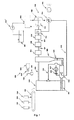
Anhand der beiliegenden Zeichnung wird die Erfindung näher erläutert. Die einzige Figur zeigt eine Schemazeichnung einer erfindungsgemäßen Anlage.With reference to the accompanying drawings, the invention will be explained in more detail. The single figure shows a schematic drawing of a plant according to the invention.
Zentraler Teil der erfindungsgemäßen Anlage ist der Gasgenerator 100, der wie in
An den Gasgenerator 100 ist über eine Leitung 305 ein Zyklon 306 angeschlossen, wo feste Stoffe (Flugasche) abgetrennt werden. Diese festen Stoffe werden über eine Schurre 204 einem Fließbettvergaser 200 zugeführt. Dem Fließbettvergaser 200 wird weiters Asche aus dem Gasgenerator 100 über einen Förderer 201 zugeführt. Dieser Förderer 201 kann als Schnecke ausgebildet sein, wodurch sich mehrere Vorteile ergeben: die Schnecke fördert dosiert, sie dichtet ab und sie zerkleinert die Asche. Die im Fließbettvergaser 200 entstehenden Gase werden über eine Rohrleitung 202 dem Gasgenerator 100 zugeführt. Da die Asche normalerweise nicht viel Kohlenstoff enthält, wird über eine Einspritzpumpe 802 und ein Ventil 803 zusätzlich flüssiger Brennstoff in den Fließbettvergaser 200 eingespritzt. Dem Fließbettvergaser 200 wird über eine Luftzuführung 203 Luft zugeführt, das entstehende Gas und die erwärmte Luft strömen dann über die Rohrleitung 202 in den Gasgenerator 100.To the
Im Bereich der Leitung 305 ist ein Analysator 300 für die Rückkopplung vorgesehen. Sie besteht aus einer Pumpe 301, die Gas aus der Leitung 305 absaugt und zu einem Kontrollbrenner 302 pumpt. Das Licht der Flamme wird durch eine Optik 304 mit Prisma zerlegt und von einer Industrie-Farbkamera 303 erfasst.In the region of the
Nach dem Zyklon gelangt das Pyrolysegas zu einem Zentrifugalfilter 400 (z.B. vom Typ der Dekantierzentrifuge, dieser ist vor allem bei Verbrennung von Stroh wichtig), von dort über eine Leitung 501 zu einem Gaswäscher 500 (entfernt Cl, S und NOx, besonders wichtig bei der Verbrennung von Altreifen oder Klärschlamm), weiter über eine Leitung 601 zu einem Absorptionsgaskühler 600 (kühlt auf etwa 25°C).After the cyclone, the pyrolysis gas passes to a centrifugal filter 400 (eg of the type of decanter centrifuge, this is especially important when burning straw), from there via a
Von dort gelangt das gereinigte und gekühlte Pyrolysegas zu einem insgesamt mit 700 bezeichneten Turbokompressorsystem. Zunächst wird es in einem Mischer 701 mit Luft vermischt. Dann wird es vom Kompressor 703 des Turboladers in einen Dieselmotor 800 gepumpt. Es ist dabei wichtig, dass im Mischer 701 so viel Luft zugemischt wird, dass das Gas/Luft-Gemisch durch die Kompression im Dieselmotor 800 allein noch nicht zündet. Erst wenn durch eine Einspritzpumpe 802' flüssiger Brennstoff aus einem Behälter 801 angesaugt und eingespritzt wird, wird die Zündung des Gas/Luft-Gemischs (im richtigen Zeitpunkt) ausgelöst. Die Abgase des Dieselmotors 800 treiben dann die Turbine 702 des Turboladers an, der seinerseits den Kompressor 703 antreibt.From there, the purified and cooled pyrolysis gas passes to a total of 700 designated turbo compressor system. First, it is mixed with air in a
Die notwendige Verbrennungsluft wird durch ein Luftgebläse 705 angesaugt und über die Luftverteilung 704 dem Mischer 701 zugeführt. Beim Start der Anlage wird die Luft von der Luftverteilung 704 auch der Turbine 702 des Turboladers zugeführt, um den Turbolader zu starten.The necessary combustion air is sucked in by an
Die erfindungsgemäße Anlage funktioniert wie folgt:The system according to the invention works as follows:
Nachdem Brennstoff auf dem Dosierförderer 101 angeschüttet wurde, werden dessen Antriebsmotoren eingeschaltet. Weiters werden auch das Luftgebläse 705 und der Förderer 201 zum Austrag der Asche eingeschaltet. Die vom Luftgebläse 705 geförderte Luft versetzt die Turbine 702 in Drehung, auf deren Welle sich der Kompressor 703 befindet, der das Gas absaugt, wodurch am Ausgang des Gasgenerators 100 der notwendige Unterdruck entsteht, sodass Luft aus der Umgebung in die Glutzone des Gasgenerators angesaugt wird, wo der Brennstoff entzündet wird. In weiterer Folge wird im Fließbettvergaser 200 Gas und erhitzte Luft gebildet, die durch die Rohrleitung 202 zurück in den Gasgenerator 100 geführt werden. Das erzeugte Gas geht dann durch den Zyklon 306, wo es vom groben Flugstaub befreit wird, der sich im Unterteil ablagert und durch die Schurre 204 in den Fließbettvergaser 200 fällt. Der Brennstoff auf dem Dosierförderer 101 wird durch die Sensoren 102, 103, 104 beobachtet. Sensor 102 ist eine Kamera, die Brennstoffstruktur, Größe, Menge, Art und Körnigkeit erfasst. Sensor 103 ist ein Feuchtigkeitsfühler und misst durch Kontaktmeßmethode die Brennstofffeuchtigkeit. Sensor 104 ist im Grunde ein Induktivitätsfühler und überwacht, dass in den Gasgenerator keine Metallgegenstände und sonstige unverbrennbare Stoffe kommen. An die Leitung 305 ist die Pumpe 301 angeschlossen, die das Gas ansaugt und in den Kontrollbrenner 302 drückt, dessen Flamme die Kamera 303 über eine Optik 304 mit Prisma beobachtet, welche das Licht in die Spektrallinien zerlegt. Daraus wird dann die Temperatur des Gases und dessen Zusammensetzung bestimmt. Der Kameraausgang wird dem Steuercomputer zugeführt, wodurch die Rückkopplung des Systems realisiert wird. Das Gas geht nach dem Zyklon 306 durch den Zentrifugalfilter 400, wo es von weiteren festen Unsauberkeiten vor dem Eingang in den durch Leitung 501 angeschlossenen Gaswäscher 500 befreit wird. Aus dem Absorptionsfilter wird das Gas durch die Leitung 601 in den Absorptionsgaskühler 600 geführt, wonach es dem Mischer 701 des Turbokompressorsystems 700 zugeführt wird. Das ausgewaschene Gas - befreit von allen unerwünschten Unsauberkeiten - wird dann mit dem Kompressor 703 in den Motor 800 gedrückt. Im Falle der Verwendung eines nicht adaptierten Dieselmotors wird die Zündung durch Einspritzen von flüssigem Brennstoff (z.B. Methylester, Bioethanol oder Benzol) mittels der Einspritzpumpe 802' gezündet.After fuel has been poured onto the
Mit der erfindungsgemäßen Anlage muss natürlich nicht unbedingt Strom erzeugt werden. Man kann das entstehende Pyrolysegas auch in einer Therme verbrennen und damit z.B. Warmwasser für eine Zentralheizung erwärmen.Of course, with the system according to the invention not necessarily electricity must be generated. The resulting pyrolysis gas can also be burned in a thermal bath and thus used, for example. Warm water for central heating.
Claims (5)
Applications Claiming Priority (1)
| Application Number | Priority Date | Filing Date | Title |
|---|---|---|---|
| AT0106805A AT502148A1 (en) | 2005-06-24 | 2005-06-24 | ANNEX FOR THE PRODUCTION OF ENERGY FROM FUMES FROM FERROUS WASTE |
Publications (2)
| Publication Number | Publication Date |
|---|---|
| EP1746145A2 true EP1746145A2 (en) | 2007-01-24 |
| EP1746145A3 EP1746145A3 (en) | 2008-08-27 |
Family
ID=37027866
Family Applications (1)
| Application Number | Title | Priority Date | Filing Date |
|---|---|---|---|
| EP06116044A Withdrawn EP1746145A3 (en) | 2005-06-24 | 2006-06-26 | Plant for the production of energy from combustible waste products |
Country Status (2)
| Country | Link |
|---|---|
| EP (1) | EP1746145A3 (en) |
| AT (1) | AT502148A1 (en) |
Cited By (5)
| Publication number | Priority date | Publication date | Assignee | Title |
|---|---|---|---|---|
| WO2011121187A3 (en) * | 2010-04-01 | 2012-08-02 | Upm-Kymmene Corporation | A method and a system for processing material that contains biomass |
| EP2990464A1 (en) * | 2013-07-11 | 2016-03-02 | Mitsubishi Heavy Industries Environmental & Chemical Engineering Co., Ltd. | Method for inhibiting occurrence of pyrolysis deposit in pyrolysis gasification system, and pyrolysis gasification system |
| CN105674285A (en) * | 2016-03-31 | 2016-06-15 | 彭本晨 | Novel domestic waste gasifier |
| CN108795505A (en) * | 2018-06-29 | 2018-11-13 | 新奥科技发展有限公司 | A kind of coal dust hydro-gasification process and system |
| EP3259530B1 (en) | 2015-02-19 | 2020-05-27 | Inray Oy | Control system for controlling feed of solid fuel in a combustion process |
Families Citing this family (1)
| Publication number | Priority date | Publication date | Assignee | Title |
|---|---|---|---|---|
| DE102010031528B4 (en) * | 2010-07-19 | 2013-04-25 | Klaus Seeger | System for determining an energy content of a solid fuel and use of the system |
Citations (3)
| Publication number | Priority date | Publication date | Assignee | Title |
|---|---|---|---|---|
| DE3744565A1 (en) * | 1986-12-30 | 1988-07-14 | Us Energy | POWER GENERATION SYSTEM AND METHOD FOR USING HYDROPYROLYSIS |
| US5584255A (en) * | 1995-06-07 | 1996-12-17 | Proler Environmental Services, Inc. | Method and apparatus for gasifying organic materials and vitrifying residual ash |
| WO2000027952A1 (en) * | 1998-11-11 | 2000-05-18 | Holderbank Financiere Glarus Ag | Method for processing bottom ash of incinerator plants |
-
2005
- 2005-06-24 AT AT0106805A patent/AT502148A1/en not_active Application Discontinuation
-
2006
- 2006-06-26 EP EP06116044A patent/EP1746145A3/en not_active Withdrawn
Patent Citations (3)
| Publication number | Priority date | Publication date | Assignee | Title |
|---|---|---|---|---|
| DE3744565A1 (en) * | 1986-12-30 | 1988-07-14 | Us Energy | POWER GENERATION SYSTEM AND METHOD FOR USING HYDROPYROLYSIS |
| US5584255A (en) * | 1995-06-07 | 1996-12-17 | Proler Environmental Services, Inc. | Method and apparatus for gasifying organic materials and vitrifying residual ash |
| WO2000027952A1 (en) * | 1998-11-11 | 2000-05-18 | Holderbank Financiere Glarus Ag | Method for processing bottom ash of incinerator plants |
Cited By (11)
| Publication number | Priority date | Publication date | Assignee | Title |
|---|---|---|---|---|
| WO2011121187A3 (en) * | 2010-04-01 | 2012-08-02 | Upm-Kymmene Corporation | A method and a system for processing material that contains biomass |
| CN103038574A (en) * | 2010-04-01 | 2013-04-10 | 芬欧汇川集团公司 | A method and a system for processing material that contains biomass |
| RU2564309C2 (en) * | 2010-04-01 | 2015-09-27 | Упм-Кюммене Корпорейшн | Method and processing of material containing biomass |
| CN103038574B (en) * | 2010-04-01 | 2015-11-25 | 芬欧汇川集团公司 | The method and system of the material of processing containing biomass |
| US9580246B2 (en) | 2010-04-01 | 2017-02-28 | Upm-Kymmene Corporation | Method and a system for processing material that contains biomass |
| EP2990464A1 (en) * | 2013-07-11 | 2016-03-02 | Mitsubishi Heavy Industries Environmental & Chemical Engineering Co., Ltd. | Method for inhibiting occurrence of pyrolysis deposit in pyrolysis gasification system, and pyrolysis gasification system |
| EP2990464A4 (en) * | 2013-07-11 | 2016-05-18 | Mitsubishi Heavy Ind Environmental & Chemical Eng Co Ltd | Method for inhibiting occurrence of pyrolysis deposit in pyrolysis gasification system, and pyrolysis gasification system |
| US10377952B2 (en) | 2013-07-11 | 2019-08-13 | Mitsubishi Heavy Industries Environmental & Chemical Engineering Co., Ltd. | Method for inhibiting occurrence of pyrolysis deposit in pyrolysis gasification system, and pyrolysis gasification system |
| EP3259530B1 (en) | 2015-02-19 | 2020-05-27 | Inray Oy | Control system for controlling feed of solid fuel in a combustion process |
| CN105674285A (en) * | 2016-03-31 | 2016-06-15 | 彭本晨 | Novel domestic waste gasifier |
| CN108795505A (en) * | 2018-06-29 | 2018-11-13 | 新奥科技发展有限公司 | A kind of coal dust hydro-gasification process and system |
Also Published As
| Publication number | Publication date |
|---|---|
| EP1746145A3 (en) | 2008-08-27 |
| AT502148A1 (en) | 2007-01-15 |
Similar Documents
| Publication | Publication Date | Title |
|---|---|---|
| EP0302310B1 (en) | Process and plant for the thermal disposal of waste | |
| EP2545142B1 (en) | Method and device for producing synthesis gas and for operating an internal combustion engine therewith | |
| DE102007005782B3 (en) | Procedure for drying dust residue in gasification of fuels e.g. coal, comprises crushing the fuel in grinder, supplying the fuel to filter/separator by conveying- and drying gas, and redirecting the conveying/drying gas into the grinder | |
| EP1746145A2 (en) | Plant for the production of energy from combustible waste products | |
| EP2563881B1 (en) | Method for gasifying biomass | |
| DE102005045166B4 (en) | Process for generating thermal energy with a FLOX burner | |
| DE4107200A1 (en) | Thermal redn. of industrial waste - by removing organic and inorganic material using low temp. distn. reactor, and treating waste material of low heat value | |
| DE112011102289B4 (en) | Reduced fossil fuel in an oxidation plant downstream of a biomass furnace | |
| EP0155607A1 (en) | Heating assembly for the gasification of solid fuels | |
| DE102008047201B4 (en) | Method and apparatus for the production of synthesis gas and for operating an internal combustion engine with it | |
| DE19846805A1 (en) | Process for gasifying or degasifying dry or moist finely ground or bulky biomass and waste comprises passing pyrolysis gas and coke to a gasifier after passing through a crusher joined to the lower end of the degasifier | |
| DE102010014479A1 (en) | Apparatus and method for hot gas production with integrated heating of a heat transfer medium | |
| EP1377649B1 (en) | Installation and method for producing energy using pyrolysis | |
| EP1436366A1 (en) | Method for the production of current from material containing carbon | |
| DE102006061583A1 (en) | Pressurized combustion chamber integrated into gas turbine plant for power generation, combines gasification, main and secondary firing, coke combustion and waste heat recovery | |
| EP2522707B1 (en) | Device for creating a flammable gas mixture | |
| DD143712A3 (en) | PROCESS FOR PROVISION OF PROCESS STEAM IN INTEGRATED BROWN COATING PLANTS | |
| DE4425117C2 (en) | Process for the combustion of sewage sludge in a fluidized bed boiler | |
| DE102010049379A1 (en) | Device useful for continuous energetic recycling of solid waste, comprises material supply device with sealing device, drying zone, smoldering zone, coke discharge device, incinerating screw and thermal post-combustion device | |
| US20200200383A1 (en) | Non-polluting Biomass Waste Processor, Components and Processes for a Use by a Municipality, Industrial, Forestry and/or Agricultural Facility | |
| DE102014001785B4 (en) | Smallest firing system for biogenic solid fuels | |
| DE102010006263A1 (en) | Preparing soil additives by biological fermentation, useful for improving the cation exchange capacity and the nutrient- and water-holding capacity of soil, comprises adding organic biomass prior to the fermentation of a liquid coal slurry | |
| EP1852494A2 (en) | Use of the glycerol phase from biodiesel production as a fuel | |
| DE102010005908A1 (en) | Process for burning industrial vegetable waste, apparatus for incinerating industrial vegetable waste and boiler for steam production | |
| DE2526947A1 (en) | Fuel gas prodn. from household or industrial waste - by reacting waste pyrolysis gases with incandescent coke |
Legal Events
| Date | Code | Title | Description |
|---|---|---|---|
| PUAI | Public reference made under article 153(3) epc to a published international application that has entered the european phase |
Free format text: ORIGINAL CODE: 0009012 |
|
| AK | Designated contracting states |
Kind code of ref document: A2 Designated state(s): AT BE BG CH CY CZ DE DK EE ES FI FR GB GR HU IE IS IT LI LT LU LV MC NL PL PT RO SE SI SK TR |
|
| AX | Request for extension of the european patent |
Extension state: AL BA HR MK YU |
|
| PUAL | Search report despatched |
Free format text: ORIGINAL CODE: 0009013 |
|
| AK | Designated contracting states |
Kind code of ref document: A3 Designated state(s): AT BE BG CH CY CZ DE DK EE ES FI FR GB GR HU IE IS IT LI LT LU LV MC NL PL PT RO SE SI SK TR |
|
| AX | Request for extension of the european patent |
Extension state: AL BA HR MK RS |
|
| RIC1 | Information provided on ipc code assigned before grant |
Ipc: F23G 5/00 20060101ALI20080718BHEP Ipc: F23J 15/00 20060101ALI20080718BHEP Ipc: F23L 15/00 20060101ALI20080718BHEP Ipc: F23J 15/02 20060101ALI20080718BHEP Ipc: F23G 5/50 20060101ALI20080718BHEP Ipc: F23G 5/46 20060101ALI20080718BHEP Ipc: F23G 7/10 20060101ALI20080718BHEP Ipc: F23J 1/00 20060101ALI20080718BHEP Ipc: F23G 5/027 20060101ALI20080718BHEP Ipc: C10J 3/66 20060101ALI20080718BHEP Ipc: C10J 3/62 20060101ALI20080718BHEP Ipc: C10J 3/46 20060101AFI20061006BHEP |
|
| AKX | Designation fees paid | ||
| STAA | Information on the status of an ep patent application or granted ep patent |
Free format text: STATUS: THE APPLICATION IS DEEMED TO BE WITHDRAWN |
|
| REG | Reference to a national code |
Ref country code: DE Ref legal event code: 8566 |
|
| 18D | Application deemed to be withdrawn |
Effective date: 20090106 |