EP1745529B1 - Hochspannungsverbinder - Google Patents
Hochspannungsverbinder Download PDFInfo
- Publication number
- EP1745529B1 EP1745529B1 EP05718735.3A EP05718735A EP1745529B1 EP 1745529 B1 EP1745529 B1 EP 1745529B1 EP 05718735 A EP05718735 A EP 05718735A EP 1745529 B1 EP1745529 B1 EP 1745529B1
- Authority
- EP
- European Patent Office
- Prior art keywords
- cone
- voltage
- connector
- mating connector
- rubber
- Prior art date
- Legal status (The legal status is an assumption and is not a legal conclusion. Google has not performed a legal analysis and makes no representation as to the accuracy of the status listed.)
- Expired - Lifetime
Links
Images
Classifications
-
- H—ELECTRICITY
- H01—ELECTRIC ELEMENTS
- H01R—ELECTRICALLY-CONDUCTIVE CONNECTIONS; STRUCTURAL ASSOCIATIONS OF A PLURALITY OF MUTUALLY-INSULATED ELECTRICAL CONNECTING ELEMENTS; COUPLING DEVICES; CURRENT COLLECTORS
- H01R13/00—Details of coupling devices of the kinds covered by groups H01R12/70 or H01R24/00 - H01R33/00
- H01R13/46—Bases; Cases
- H01R13/53—Bases or cases for heavy duty; Bases or cases for high voltage with means for preventing corona or arcing
Definitions
- the invention relates to a high-voltage connector, having a plug with a rubber cone for insertion into a socket or mating connector-half.
- a connector of this kind is also referred to as a rubber-cone plug system and is used in particular for connecting X-ray generators to high-voltage generators that operate with relatively high grid and/or focusing voltages.
- a high-voltage connector according to the preamble of claim 1 is known from FR 2 755 797 A1 .
- a general object of the invention is therefore to provide a high-voltage connector of the kind specified in the opening paragraph whose insulation against high voltages will be reliably maintained over a long period.
- the intention of the invention is, in particular, to provide a high-voltage connector of the kind specified in the opening paragraph that can be produced even for relatively high grid voltages and/or focusing voltages in a range of, for example, up to approximately 30 kV, which voltages are superimposed on the high voltage proper of approximately 160 kV.
- the intention with the invention is also to provide a high-voltage connector of the kind specified in the opening paragraph that can be constructed relatively simply and manufactured inexpensively.
- a particular advantage of this solution is that, for example, single-pole high voltages for a plurality of relatively high grid or focusing voltages can be carried by a plug-in connector without this detracting from the insulation of the connector against high voltages.
- a further advantage of this solution lies in the fact that the insulation against high voltage is not reduced even by a large number of temperature cycles that involve considerable thermal fluctuations due to the varying operating temperatures of the pieces of equipment that are connected.
- the high-voltage connector can also be produced in a relatively small form.
- high-voltage connector which is able to carry, or in other words insulates, a single-pole high voltage of up to approximately 200 kV and, on this potential, two grid or focusing voltages of up to approximately 30 kV.
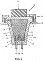
- the high-voltage connector is composed essentially of a plug 10 and a socket or mating connector-half 20. Connected to the plug 10 is the end of a high-voltage cable 11, while the socket 20 is installed in the usual way in a housing 30 of a high-voltage device such as, for example, a high-voltage generator or an X-ray generator.
- a high-voltage device such as, for example, a high-voltage generator or an X-ray generator.
- the plug 10 is locked to the socket 20 by a fastening means 12 such as, for example, a bayonet lock or screwed closure.
- a fastening means 12 such as, for example, a bayonet lock or screwed closure.
- An essential part of the plug 10 is the rubber cone 131; 132, 133, which is composed of a first cone portion 131 and at least two second cone portions 132, 133 at the tip of the first cone portion 131.
- a first expansion space 22 which is at least sufficiently deep to provide enough room for axial thermal expansion of the rubber cone 131; 132, 133 when heated to any realistic operating temperature by the components that are connected.
- the first expansion space 22 is filled with air. It may however equally well contain some other gas such as, for example, nitrogen or may, if required, be under vacuum.
- the first expansion space 22 may also be filled with a material that is able to be compressed by the rubber cone as it expands thermally.
- a material of this kind is for example a suitable soft rubber or silicone containing gas inclusions.
- Incorporated in the tip 15 of the cone are two female contacts 16, 17 to act as contacts for the high voltage and, between them, a slot 18.
- the walls of the slot 18 are preferably parallel to one another or extend towards one another in a substantially conical shape.
- the width of the slot (in the direction perpendicular to the plane of the drawing in Fig. 1 ) covers the full diameter of the rubber cone. For each bore 16; 17, this slot forms a boundary of an individual second cone portion 132, 133.
- This ridge 25 is of substantially the same width as the slot 18, i.e. it extends in the slot 18 across the full diameter of the rubber cone.
- the ridge 25 tapers in this case in its lengthwise direction in a substantially conical shape. What is achieved in this way is that when the plug 10 is inserted in the mating connector-half 20, a correspondingly high applied pressure arises between the ridge 25 and the walls of the slot 18, and the second cone portions 132, 133 are thus also each enclosed by a tight-fitting joint. High insulation against high voltages is achieved in this way between the contacts pins 23, 24 and between the female contacts 16, 17.
- the ridge 25 also helps to increase the applied pressure between the second cone portions 132, 133 and the regions of the inner wall of the mating connector-half 20 that bear against them.
- Fig. 1 there may equally well be incorporated in the tip of the cone four first female contacts, arranged substantially at the corners of a square, for corresponding contact pins, together with a slot, which is cruciform in this case, between the female contacts, to produce four second cone portions each with a female contact.
- the first contact pin 23 for example may be used as a contact for the high voltage and the second contact pin 24 as a contact for the grid or focusing voltage superimposed on the high voltage.
- the female contacts 16, 17 are provided with known contacting faces or are clad in a known manner. The conductors connected to the female contacts, which run through the rubber cone 131,132; 131, 133, are not shown.
- the first angle A to the vertical at which the first cone portion 131 is applied to the inner wall of the mating connector-half 20 is larger (and is for example approximately 6°) than the second angle B to the vertical (which is for example approximately 2°) at which the second cone portions 132, 133 are applied to the said inner wall.
- both the angles of application A, B to be made of the same size.
- the angle of application to the vertical between the ridge 25 and the side-walls of the slot 18 substantially corresponds to the second angle of application B between the second cone portions 132, 133 and the inner wall of the mating connector-half 20, or is smaller than it.
- the first cone portion 131 serves to insulate the high voltage (high-voltage cone or main cone), whereas the second cone portions 132, 133 perform the function of insulating the grid and/or focusing voltages (grid cones).
- the high-voltage plug-in connector according to the invention opens up the possibility of using, in high-grade X-ray systems, single-pole high-powered X-ray tubes operating at a high voltage level (such as 160 kV single pole for example) and having a plurality of high grid or focusing voltages (e.g. twice 10 kV), for which tubes is required a rubber-cone plug-in connector having a plurality of grid conductors or heating conductors that is more stable at temperature and better insulated against high voltages.
- a high voltage level such as 160 kV single pole for example
- a plurality of high grid or focusing voltages e.g. twice 10 kV
Landscapes
- Connector Housings Or Holding Contact Members (AREA)
Claims (8)
- Hochspannungssteckverbinder, der einen Stecker (10) mit einem Gummikonus (131; 132, 133) zum Einführen in eine passende Steckverbinder-Hälfte (20) aufweist, wobei der Gummikonus einen ersten Abschnitt (131) und zumindest zwei zweite Konus-Abschnitte (132, 133) aufweist, dadurch gekennzeichnet, dass die zumindest zwei zweiten Konus-Abschnitte jeweilige Buchsenkontakte (16, 17) aufweisen, um einen Kontakt mit den jeweiligen Kontaktstiften ((23, 24) an der passenden Steckverbinder-Hälfte (20) herzustellen, wobei die zweiten Konus-Abschnitte (132, 133) durch eine geschlitzte Vertiefung (18) im Gummikonus voneinander getrennt sind, in die sich ein, in seine Längsrichtung spitz zulaufender und im Wesentlichen konischer Grat (25), der auf dem passenden Steckverbinder (20) angeordnet ist, erstreckt, um eine genau eingepasste und gegen Hochspannung isolierte Fügestelle zu bilden, wobei der Grat (25) und die Wände der Vertiefung (18) derart ausgeführt sind, dass jeder der zweiten Konus-Abschnitte (132, 133) aufgrund eines hohen Drucks durch eine genau eingepasste Fügestelle eingeschlossen wird.
- Hochspannungssteckverbinder nach Anspruch 1, wobei eine genau eingepasste, gegen Hochspannung isolierte Fügestelle (14) zwischen dem Gummikonus (131; 132, 133) und der passenden Steckverbinder-Hälfte (20) besteht, und wobei ein erster Applikationswinkel (A) der genau eingepassten Fügestelle (14) zwischen dem ersten Abschnitt (131) und der passenden Steckverbinder-Hälfte (20) größer oder gleich einem zweiten Applikationswinkel (B) der genau eingepassten Fügestelle (14) zwischen dem zweiten Konus-Abschnitt (132, 133) und der passenden Steckverbinder-Hälfte (20) ist.
- Hochspannungssteckverbinder nach Anspruch 1, wobei, wenn sich der Steckverbinder im nicht vollkommen eingeführten Zustand befindet, ein erster Ausdehnungsraum (22), in den sich der Gummikonus thermisch ausdehnen kann, zwischen der Spitze (15) des Gummikonus und einem Grund (21) der passenden Steckverbinder-Hälfte (20) vorhanden ist.
- Hochspannungssteckverbinder nach Anspruch 1, wobei die Tiefe der geschlitzten Vertiefung (18) und die Länge des Grats (25) einander derart angepasst sind, dass, wenn sich der Steckverbinder im nicht vollkommen eingeführten Zustand befindet, ein zweiter Ausdehnungsraum (19), in den sich der Gummikonus thermisch ausdehnen kann, an der Spitze (25) des Gummikonus vorhanden ist.
- Hochspannungssteckverbinder nach Anspruch 3 oder 4, wobei der Ausdehnungsraum (22; 19) mit einem Medium ausgefüllt ist, das durch thermische Ausdehnung des Gummikonus (131; 132, 133) komprimiert werden kann.
- Hochspannungssteckverbinder nach Anspruch 5, wobei das Medium ein Gas und/ oder ein Silikonmaterial mit Gaseinschlüssen ist.
- Hochspannungssteckverbinder, im Speziellen zum Verbinden eines Röntgenstrahlengenerators mit einem Hochspannungsgenerator, der zumindest einen Hochspannungssteckverbinder nach irgendeinem der vorherigen Ansprüche aufweist.
- Röntgenstrahlenanlage, die einen Röntgenstrahlengenerator und einen Hochspannungssteckverbinder nach irgendeinem der Ansprüche 1 bis 8 aufweist.
Priority Applications (1)
| Application Number | Priority Date | Filing Date | Title |
|---|---|---|---|
| EP05718735.3A EP1745529B8 (de) | 2004-04-29 | 2005-04-15 | Hochspannungsverbinder |
Applications Claiming Priority (3)
| Application Number | Priority Date | Filing Date | Title |
|---|---|---|---|
| EP04101834 | 2004-04-29 | ||
| PCT/IB2005/051239 WO2005107021A1 (en) | 2004-04-29 | 2005-04-15 | High-voltage connector |
| EP05718735.3A EP1745529B8 (de) | 2004-04-29 | 2005-04-15 | Hochspannungsverbinder |
Publications (3)
| Publication Number | Publication Date |
|---|---|
| EP1745529A1 EP1745529A1 (de) | 2007-01-24 |
| EP1745529B1 true EP1745529B1 (de) | 2016-02-24 |
| EP1745529B8 EP1745529B8 (de) | 2016-06-15 |
Family
ID=34963703
Family Applications (1)
| Application Number | Title | Priority Date | Filing Date |
|---|---|---|---|
| EP05718735.3A Expired - Lifetime EP1745529B8 (de) | 2004-04-29 | 2005-04-15 | Hochspannungsverbinder |
Country Status (5)
| Country | Link |
|---|---|
| US (1) | US7601014B2 (de) |
| EP (1) | EP1745529B8 (de) |
| JP (1) | JP4610609B2 (de) |
| CN (1) | CN1950977B (de) |
| WO (1) | WO2005107021A1 (de) |
Families Citing this family (10)
| Publication number | Priority date | Publication date | Assignee | Title |
|---|---|---|---|---|
| JP5414167B2 (ja) * | 2007-11-02 | 2014-02-12 | 株式会社東芝 | X線管装置 |
| WO2012001573A1 (en) | 2010-06-29 | 2012-01-05 | Koninklijke Philips Electronics N.V. | High-voltage connector |
| EP2490302B1 (de) * | 2011-02-15 | 2016-06-08 | GE Sensing & Inspection Technologies GmbH | Hochspannungs-Steckverbindungsteil für ein Hochspannungskabel und Verfahren zur Herstellung desselben |
| US8817950B2 (en) * | 2011-12-22 | 2014-08-26 | Moxtek, Inc. | X-ray tube to power supply connector |
| FR2994619B1 (fr) * | 2012-08-17 | 2016-07-08 | Socapex Amphenol | Connecteur electrique pour haut debit |
| US8956168B2 (en) * | 2013-05-14 | 2015-02-17 | Kuwait University | Electrical outlet safety device |
| DE102014201514B4 (de) * | 2014-01-28 | 2021-09-16 | Siemens Healthcare Gmbh | Röntgenstrahler |
| CN106486257B (zh) | 2014-06-23 | 2018-05-04 | 上海联影医疗科技有限公司 | 高压发生器 |
| JP6936067B2 (ja) * | 2017-07-25 | 2021-09-15 | キヤノン電子管デバイス株式会社 | X線管装置 |
| CN109301560B (zh) * | 2018-10-19 | 2020-10-20 | 岳西县明杰电子有限公司 | 一种用于手机充电器变压装置的联动挤压绝缘装置 |
Family Cites Families (25)
| Publication number | Priority date | Publication date | Assignee | Title |
|---|---|---|---|---|
| DE1092090B (de) * | 1959-07-24 | 1960-11-03 | Siemens Reiniger Werke Ag | Hochspannungskabelsteckverbindung, insbesondere fuer Roentgenroehrenschutzgehaeuse |
| US3888559A (en) * | 1972-04-13 | 1975-06-10 | Amp Inc | High voltage quick disconnect assembly |
| JPS5321493Y2 (de) * | 1973-03-05 | 1978-06-05 | ||
| US3871736A (en) * | 1973-09-20 | 1975-03-18 | Amp Inc | Connectors providing interconnection between closely spaced conductors and widely spaced terminals |
| JPS5150118A (ja) * | 1974-10-24 | 1976-05-01 | Japan Steel Works Ltd | Kanshoki |
| JPS53131620A (en) * | 1977-07-18 | 1978-11-16 | Japan Steel Works Ltd:The | Shock absorber for railway vehicle |
| JPS54114087U (de) * | 1978-01-30 | 1979-08-10 | ||
| US4296986A (en) * | 1979-06-18 | 1981-10-27 | Amp Incorporated | High voltage hermetically sealed connector |
| US4335928A (en) * | 1980-06-30 | 1982-06-22 | General Electric Company | High voltage connector for x-ray equipment |
| GB8529454D0 (en) * | 1985-11-29 | 1986-01-08 | Raychem Gmbh | Cable connection |
| US5173062A (en) * | 1990-08-31 | 1992-12-22 | Koito Manufacturing Co., Ltd. | Discharge lamp connector assembly |
| JPH07118344B2 (ja) * | 1990-11-29 | 1995-12-18 | 株式会社小糸製作所 | 放電ランプ用コネクター |
| US5358419A (en) * | 1993-08-30 | 1994-10-25 | General Electric Company | Electrical power tube connector |
| NO300518B1 (no) * | 1994-09-30 | 1997-06-09 | Alcatel Kabel Norge As | Anordning for sammenkobling av en kabel og et apparat |
| DE4437382C1 (de) * | 1994-10-19 | 1995-11-23 | Philips Patentverwaltung | Verfahren zur Verbesserung der Hochspannungsfestigkeit einer Hochspannungssteckverbindung |
| CN1153409A (zh) * | 1995-08-09 | 1997-07-02 | 住友电装株式会社 | 连接器用锁定装置及其在充电连接器和/或高压电缆连接器中的应用 |
| FR2755797B1 (fr) * | 1996-11-14 | 1998-12-31 | Ge Medical Syst Sa | Ensemble a haute tension a elements separables |
| JP3262726B2 (ja) * | 1996-12-16 | 2002-03-04 | 日本圧着端子製造株式会社 | コネクタ |
| FR2769756B1 (fr) * | 1997-10-09 | 1999-12-31 | Ge Medical Syst Sa | Bague-soufflet pour connecteur haute-tension et connecteur haute-tension obtenu |
| FR2817667B1 (fr) * | 2000-12-01 | 2003-01-10 | Ge Med Sys Global Tech Co Llc | Dispositif de connexion electrique a haute tension |
| DE10142195A1 (de) * | 2001-08-29 | 2003-04-24 | Harting Kgaa | Steckverbinder mit Isolations-und Dichtungselement |
| US6556654B1 (en) * | 2001-11-09 | 2003-04-29 | Varian Medical Systems, Inc. | High voltage cable and clamp system for an X-ray tube |
| US6816574B2 (en) * | 2002-08-06 | 2004-11-09 | Varian Medical Systems, Inc. | X-ray tube high voltage connector |
| CN100459304C (zh) * | 2003-01-07 | 2009-02-04 | 皇家飞利浦电子股份有限公司 | 高电压连接器 |
| US7445517B2 (en) * | 2004-04-16 | 2008-11-04 | Varian Medical Systems, Inc. | High voltage cable assembly with ARC protection |
-
2005
- 2005-04-15 JP JP2007510177A patent/JP4610609B2/ja not_active Expired - Fee Related
- 2005-04-15 EP EP05718735.3A patent/EP1745529B8/de not_active Expired - Lifetime
- 2005-04-15 US US11/568,272 patent/US7601014B2/en not_active Expired - Lifetime
- 2005-04-15 CN CN2005800135972A patent/CN1950977B/zh not_active Expired - Fee Related
- 2005-04-15 WO PCT/IB2005/051239 patent/WO2005107021A1/en not_active Ceased
Also Published As
| Publication number | Publication date |
|---|---|
| US20080242134A1 (en) | 2008-10-02 |
| CN1950977B (zh) | 2010-09-29 |
| EP1745529B8 (de) | 2016-06-15 |
| JP2007535108A (ja) | 2007-11-29 |
| US7601014B2 (en) | 2009-10-13 |
| WO2005107021A1 (en) | 2005-11-10 |
| CN1950977A (zh) | 2007-04-18 |
| JP4610609B2 (ja) | 2011-01-12 |
| EP1745529A1 (de) | 2007-01-24 |
Similar Documents
| Publication | Publication Date | Title |
|---|---|---|
| EP1745529B1 (de) | Hochspannungsverbinder | |
| US2320332A (en) | Electricity conductor unit | |
| US3474394A (en) | Means for making electrical connections | |
| WO2014150568A1 (en) | High voltage power connector | |
| AU2014202028B2 (en) | Gelatinous dielectric material for high voltage connector | |
| EP3172745B1 (de) | Elektrischer verbinder | |
| US4494811A (en) | High voltage connector assembly with internal oil expansion chamber | |
| KR102180277B1 (ko) | 라운드형 온도감지 전류차단 콘센트 | |
| US7204705B2 (en) | High-voltage connector | |
| EP0033411B1 (de) | Wechselstrom-Steckdose für elektrische Ausrüstung | |
| KR102180272B1 (ko) | 팽창형 온도감지 전류차단 콘센트 | |
| US20240106150A1 (en) | Electrical Connector | |
| GB2292486A (en) | Electrical connector | |
| KR102180278B1 (ko) | 엠보형 온도감지 전류차단 콘센트 | |
| KR102180275B1 (ko) | 플런저형 온도감지 전류차단 콘센트 | |
| JP2005524939A (ja) | 特にデータ電送のための付加的な接点装置を備えたコネクタ装置 | |
| CN116706625A (zh) | 用于空间领域的高压电连接器 | |
| CN110521067B (zh) | 具有用于螺接的高电流接触体的高电流连接器 | |
| US8297995B2 (en) | Device for preventing the establishment of an electric arc between two conductive elements | |
| BR102023019142A2 (pt) | Conector elétrico | |
| SU1571687A1 (ru) | Комбинированный стержневой изол тор |
Legal Events
| Date | Code | Title | Description |
|---|---|---|---|
| PUAI | Public reference made under article 153(3) epc to a published international application that has entered the european phase |
Free format text: ORIGINAL CODE: 0009012 |
|
| 17P | Request for examination filed |
Effective date: 20061129 |
|
| AK | Designated contracting states |
Kind code of ref document: A1 Designated state(s): AT BE BG CH CY CZ DE DK EE ES FI FR GB GR HU IE IS IT LI LT LU MC NL PL PT RO SE SI SK TR |
|
| DAX | Request for extension of the european patent (deleted) | ||
| 17Q | First examination report despatched |
Effective date: 20080619 |
|
| RAP1 | Party data changed (applicant data changed or rights of an application transferred) |
Owner name: KONINKLIJKE PHILIPS N.V. Owner name: PHILIPS INTELLECTUAL PROPERTY & STANDARDS GMBH |
|
| GRAP | Despatch of communication of intention to grant a patent |
Free format text: ORIGINAL CODE: EPIDOSNIGR1 |
|
| INTG | Intention to grant announced |
Effective date: 20150821 |
|
| GRAS | Grant fee paid |
Free format text: ORIGINAL CODE: EPIDOSNIGR3 |
|
| GRAA | (expected) grant |
Free format text: ORIGINAL CODE: 0009210 |
|
| AK | Designated contracting states |
Kind code of ref document: B1 Designated state(s): AT BE BG CH CY CZ DE DK EE ES FI FR GB GR HU IE IS IT LI LT LU MC NL PL PT RO SE SI SK TR |
|
| REG | Reference to a national code |
Ref country code: GB Ref legal event code: FG4D |
|
| REG | Reference to a national code |
Ref country code: DE Ref legal event code: R081 Ref document number: 602005048498 Country of ref document: DE Owner name: PHILIPS GMBH, DE Free format text: FORMER OWNERS: PHILIPS INTELLECTUAL PROPERTY & STANDARDS GMBH, 20099 HAMBURG, DE; KONINKLIJKE PHILIPS ELECTRONICS N.V., EINDHOVEN, NL |
|
| REG | Reference to a national code |
Ref country code: CH Ref legal event code: EP |
|
| REG | Reference to a national code |
Ref country code: AT Ref legal event code: REF Ref document number: 777165 Country of ref document: AT Kind code of ref document: T Effective date: 20160315 |
|
| REG | Reference to a national code |
Ref country code: IE Ref legal event code: FG4D |
|
| REG | Reference to a national code |
Ref country code: DE Ref legal event code: R096 Ref document number: 602005048498 Country of ref document: DE |
|
| GRAT | Correction requested after decision to grant or after decision to maintain patent in amended form |
Free format text: ORIGINAL CODE: EPIDOSNCDEC |
|
| RAP2 | Party data changed (patent owner data changed or rights of a patent transferred) |
Owner name: PHILIPS INTELLECTUAL PROPERTY & STANDARDS GMBH Owner name: KONINKLIJKE PHILIPS N.V. |
|
| REG | Reference to a national code |
Ref country code: NL Ref legal event code: FP |
|
| REG | Reference to a national code |
Ref country code: LT Ref legal event code: MG4D |
|
| PGFP | Annual fee paid to national office [announced via postgrant information from national office to epo] |
Ref country code: NL Payment date: 20160426 Year of fee payment: 12 |
|
| REG | Reference to a national code |
Ref country code: AT Ref legal event code: MK05 Ref document number: 777165 Country of ref document: AT Kind code of ref document: T Effective date: 20160224 |
|
| PG25 | Lapsed in a contracting state [announced via postgrant information from national office to epo] |
Ref country code: ES Free format text: LAPSE BECAUSE OF FAILURE TO SUBMIT A TRANSLATION OF THE DESCRIPTION OR TO PAY THE FEE WITHIN THE PRESCRIBED TIME-LIMIT Effective date: 20160224 Ref country code: IT Free format text: LAPSE BECAUSE OF FAILURE TO SUBMIT A TRANSLATION OF THE DESCRIPTION OR TO PAY THE FEE WITHIN THE PRESCRIBED TIME-LIMIT Effective date: 20160224 Ref country code: FI Free format text: LAPSE BECAUSE OF FAILURE TO SUBMIT A TRANSLATION OF THE DESCRIPTION OR TO PAY THE FEE WITHIN THE PRESCRIBED TIME-LIMIT Effective date: 20160224 Ref country code: GR Free format text: LAPSE BECAUSE OF FAILURE TO SUBMIT A TRANSLATION OF THE DESCRIPTION OR TO PAY THE FEE WITHIN THE PRESCRIBED TIME-LIMIT Effective date: 20160525 |
|
| PG25 | Lapsed in a contracting state [announced via postgrant information from national office to epo] |
Ref country code: LT Free format text: LAPSE BECAUSE OF FAILURE TO SUBMIT A TRANSLATION OF THE DESCRIPTION OR TO PAY THE FEE WITHIN THE PRESCRIBED TIME-LIMIT Effective date: 20160224 Ref country code: PL Free format text: LAPSE BECAUSE OF FAILURE TO SUBMIT A TRANSLATION OF THE DESCRIPTION OR TO PAY THE FEE WITHIN THE PRESCRIBED TIME-LIMIT Effective date: 20160224 Ref country code: SE Free format text: LAPSE BECAUSE OF FAILURE TO SUBMIT A TRANSLATION OF THE DESCRIPTION OR TO PAY THE FEE WITHIN THE PRESCRIBED TIME-LIMIT Effective date: 20160224 Ref country code: BE Free format text: LAPSE BECAUSE OF NON-PAYMENT OF DUE FEES Effective date: 20160430 Ref country code: AT Free format text: LAPSE BECAUSE OF FAILURE TO SUBMIT A TRANSLATION OF THE DESCRIPTION OR TO PAY THE FEE WITHIN THE PRESCRIBED TIME-LIMIT Effective date: 20160224 Ref country code: PT Free format text: LAPSE BECAUSE OF FAILURE TO SUBMIT A TRANSLATION OF THE DESCRIPTION OR TO PAY THE FEE WITHIN THE PRESCRIBED TIME-LIMIT Effective date: 20160624 |
|
| PG25 | Lapsed in a contracting state [announced via postgrant information from national office to epo] |
Ref country code: EE Free format text: LAPSE BECAUSE OF FAILURE TO SUBMIT A TRANSLATION OF THE DESCRIPTION OR TO PAY THE FEE WITHIN THE PRESCRIBED TIME-LIMIT Effective date: 20160224 Ref country code: DK Free format text: LAPSE BECAUSE OF FAILURE TO SUBMIT A TRANSLATION OF THE DESCRIPTION OR TO PAY THE FEE WITHIN THE PRESCRIBED TIME-LIMIT Effective date: 20160224 |
|
| REG | Reference to a national code |
Ref country code: DE Ref legal event code: R097 Ref document number: 602005048498 Country of ref document: DE |
|
| PG25 | Lapsed in a contracting state [announced via postgrant information from national office to epo] |
Ref country code: SK Free format text: LAPSE BECAUSE OF FAILURE TO SUBMIT A TRANSLATION OF THE DESCRIPTION OR TO PAY THE FEE WITHIN THE PRESCRIBED TIME-LIMIT Effective date: 20160224 Ref country code: CZ Free format text: LAPSE BECAUSE OF FAILURE TO SUBMIT A TRANSLATION OF THE DESCRIPTION OR TO PAY THE FEE WITHIN THE PRESCRIBED TIME-LIMIT Effective date: 20160224 Ref country code: RO Free format text: LAPSE BECAUSE OF FAILURE TO SUBMIT A TRANSLATION OF THE DESCRIPTION OR TO PAY THE FEE WITHIN THE PRESCRIBED TIME-LIMIT Effective date: 20160224 |
|
| REG | Reference to a national code |
Ref country code: CH Ref legal event code: PL |
|
| PG25 | Lapsed in a contracting state [announced via postgrant information from national office to epo] |
Ref country code: BE Free format text: LAPSE BECAUSE OF FAILURE TO SUBMIT A TRANSLATION OF THE DESCRIPTION OR TO PAY THE FEE WITHIN THE PRESCRIBED TIME-LIMIT Effective date: 20160224 Ref country code: LU Free format text: LAPSE BECAUSE OF FAILURE TO SUBMIT A TRANSLATION OF THE DESCRIPTION OR TO PAY THE FEE WITHIN THE PRESCRIBED TIME-LIMIT Effective date: 20160415 |
|
| PLBE | No opposition filed within time limit |
Free format text: ORIGINAL CODE: 0009261 |
|
| STAA | Information on the status of an ep patent application or granted ep patent |
Free format text: STATUS: NO OPPOSITION FILED WITHIN TIME LIMIT |
|
| GBPC | Gb: european patent ceased through non-payment of renewal fee |
Effective date: 20160524 |
|
| REG | Reference to a national code |
Ref country code: IE Ref legal event code: MM4A |
|
| REG | Reference to a national code |
Ref country code: FR Ref legal event code: ST Effective date: 20161230 |
|
| PG25 | Lapsed in a contracting state [announced via postgrant information from national office to epo] |
Ref country code: CH Free format text: LAPSE BECAUSE OF NON-PAYMENT OF DUE FEES Effective date: 20160430 Ref country code: LI Free format text: LAPSE BECAUSE OF NON-PAYMENT OF DUE FEES Effective date: 20160430 Ref country code: FR Free format text: LAPSE BECAUSE OF NON-PAYMENT OF DUE FEES Effective date: 20160502 |
|
| 26N | No opposition filed |
Effective date: 20161125 |
|
| PG25 | Lapsed in a contracting state [announced via postgrant information from national office to epo] |
Ref country code: SI Free format text: LAPSE BECAUSE OF FAILURE TO SUBMIT A TRANSLATION OF THE DESCRIPTION OR TO PAY THE FEE WITHIN THE PRESCRIBED TIME-LIMIT Effective date: 20160224 Ref country code: BG Free format text: LAPSE BECAUSE OF FAILURE TO SUBMIT A TRANSLATION OF THE DESCRIPTION OR TO PAY THE FEE WITHIN THE PRESCRIBED TIME-LIMIT Effective date: 20160524 |
|
| PG25 | Lapsed in a contracting state [announced via postgrant information from national office to epo] |
Ref country code: GB Free format text: LAPSE BECAUSE OF NON-PAYMENT OF DUE FEES Effective date: 20160524 Ref country code: IE Free format text: LAPSE BECAUSE OF NON-PAYMENT OF DUE FEES Effective date: 20160415 |
|
| REG | Reference to a national code |
Ref country code: NL Ref legal event code: MM Effective date: 20170501 |
|
| PG25 | Lapsed in a contracting state [announced via postgrant information from national office to epo] |
Ref country code: NL Free format text: LAPSE BECAUSE OF NON-PAYMENT OF DUE FEES Effective date: 20170501 |
|
| REG | Reference to a national code |
Ref country code: DE Ref legal event code: R082 Ref document number: 602005048498 Country of ref document: DE Representative=s name: MEISSNER BOLTE PATENTANWAELTE RECHTSANWAELTE P, DE Ref country code: DE Ref legal event code: R081 Ref document number: 602005048498 Country of ref document: DE Owner name: PHILIPS GMBH, DE Free format text: FORMER OWNER: PHILIPS INTELLECTUAL PROPERTY & STANDARDS GMBH, 20099 HAMBURG, DE |
|
| PG25 | Lapsed in a contracting state [announced via postgrant information from national office to epo] |
Ref country code: CY Free format text: LAPSE BECAUSE OF FAILURE TO SUBMIT A TRANSLATION OF THE DESCRIPTION OR TO PAY THE FEE WITHIN THE PRESCRIBED TIME-LIMIT Effective date: 20160224 Ref country code: HU Free format text: LAPSE BECAUSE OF FAILURE TO SUBMIT A TRANSLATION OF THE DESCRIPTION OR TO PAY THE FEE WITHIN THE PRESCRIBED TIME-LIMIT; INVALID AB INITIO Effective date: 20050415 |
|
| PG25 | Lapsed in a contracting state [announced via postgrant information from national office to epo] |
Ref country code: TR Free format text: LAPSE BECAUSE OF FAILURE TO SUBMIT A TRANSLATION OF THE DESCRIPTION OR TO PAY THE FEE WITHIN THE PRESCRIBED TIME-LIMIT Effective date: 20160224 Ref country code: IS Free format text: LAPSE BECAUSE OF FAILURE TO SUBMIT A TRANSLATION OF THE DESCRIPTION OR TO PAY THE FEE WITHIN THE PRESCRIBED TIME-LIMIT Effective date: 20160224 Ref country code: MC Free format text: LAPSE BECAUSE OF FAILURE TO SUBMIT A TRANSLATION OF THE DESCRIPTION OR TO PAY THE FEE WITHIN THE PRESCRIBED TIME-LIMIT Effective date: 20160224 |
|
| PGFP | Annual fee paid to national office [announced via postgrant information from national office to epo] |
Ref country code: DE Payment date: 20210428 Year of fee payment: 17 |
|
| REG | Reference to a national code |
Ref country code: DE Ref legal event code: R119 Ref document number: 602005048498 Country of ref document: DE |
|
| PG25 | Lapsed in a contracting state [announced via postgrant information from national office to epo] |
Ref country code: DE Free format text: LAPSE BECAUSE OF NON-PAYMENT OF DUE FEES Effective date: 20221103 |