EP1745529B1 - High-voltage connector - Google Patents
High-voltage connector Download PDFInfo
- Publication number
- EP1745529B1 EP1745529B1 EP05718735.3A EP05718735A EP1745529B1 EP 1745529 B1 EP1745529 B1 EP 1745529B1 EP 05718735 A EP05718735 A EP 05718735A EP 1745529 B1 EP1745529 B1 EP 1745529B1
- Authority
- EP
- European Patent Office
- Prior art keywords
- cone
- voltage
- connector
- mating connector
- rubber
- Prior art date
- Legal status (The legal status is an assumption and is not a legal conclusion. Google has not performed a legal analysis and makes no representation as to the accuracy of the status listed.)
- Expired - Lifetime
Links
Images
Classifications
-
- H—ELECTRICITY
- H01—ELECTRIC ELEMENTS
- H01R—ELECTRICALLY-CONDUCTIVE CONNECTIONS; STRUCTURAL ASSOCIATIONS OF A PLURALITY OF MUTUALLY-INSULATED ELECTRICAL CONNECTING ELEMENTS; COUPLING DEVICES; CURRENT COLLECTORS
- H01R13/00—Details of coupling devices of the kinds covered by groups H01R12/70 or H01R24/00 - H01R33/00
- H01R13/46—Bases; Cases
- H01R13/53—Bases or cases for heavy duty; Bases or cases for high voltage with means for preventing corona or arcing
Definitions
- the invention relates to a high-voltage connector, having a plug with a rubber cone for insertion into a socket or mating connector-half.
- a connector of this kind is also referred to as a rubber-cone plug system and is used in particular for connecting X-ray generators to high-voltage generators that operate with relatively high grid and/or focusing voltages.
- a high-voltage connector according to the preamble of claim 1 is known from FR 2 755 797 A1 .
- a general object of the invention is therefore to provide a high-voltage connector of the kind specified in the opening paragraph whose insulation against high voltages will be reliably maintained over a long period.
- the intention of the invention is, in particular, to provide a high-voltage connector of the kind specified in the opening paragraph that can be produced even for relatively high grid voltages and/or focusing voltages in a range of, for example, up to approximately 30 kV, which voltages are superimposed on the high voltage proper of approximately 160 kV.
- the intention with the invention is also to provide a high-voltage connector of the kind specified in the opening paragraph that can be constructed relatively simply and manufactured inexpensively.
- a particular advantage of this solution is that, for example, single-pole high voltages for a plurality of relatively high grid or focusing voltages can be carried by a plug-in connector without this detracting from the insulation of the connector against high voltages.
- a further advantage of this solution lies in the fact that the insulation against high voltage is not reduced even by a large number of temperature cycles that involve considerable thermal fluctuations due to the varying operating temperatures of the pieces of equipment that are connected.
- the high-voltage connector can also be produced in a relatively small form.
- high-voltage connector which is able to carry, or in other words insulates, a single-pole high voltage of up to approximately 200 kV and, on this potential, two grid or focusing voltages of up to approximately 30 kV.
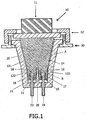
- the high-voltage connector is composed essentially of a plug 10 and a socket or mating connector-half 20. Connected to the plug 10 is the end of a high-voltage cable 11, while the socket 20 is installed in the usual way in a housing 30 of a high-voltage device such as, for example, a high-voltage generator or an X-ray generator.
- a high-voltage device such as, for example, a high-voltage generator or an X-ray generator.
- the plug 10 is locked to the socket 20 by a fastening means 12 such as, for example, a bayonet lock or screwed closure.
- a fastening means 12 such as, for example, a bayonet lock or screwed closure.
- An essential part of the plug 10 is the rubber cone 131; 132, 133, which is composed of a first cone portion 131 and at least two second cone portions 132, 133 at the tip of the first cone portion 131.
- a first expansion space 22 which is at least sufficiently deep to provide enough room for axial thermal expansion of the rubber cone 131; 132, 133 when heated to any realistic operating temperature by the components that are connected.
- the first expansion space 22 is filled with air. It may however equally well contain some other gas such as, for example, nitrogen or may, if required, be under vacuum.
- the first expansion space 22 may also be filled with a material that is able to be compressed by the rubber cone as it expands thermally.
- a material of this kind is for example a suitable soft rubber or silicone containing gas inclusions.
- Incorporated in the tip 15 of the cone are two female contacts 16, 17 to act as contacts for the high voltage and, between them, a slot 18.
- the walls of the slot 18 are preferably parallel to one another or extend towards one another in a substantially conical shape.
- the width of the slot (in the direction perpendicular to the plane of the drawing in Fig. 1 ) covers the full diameter of the rubber cone. For each bore 16; 17, this slot forms a boundary of an individual second cone portion 132, 133.
- This ridge 25 is of substantially the same width as the slot 18, i.e. it extends in the slot 18 across the full diameter of the rubber cone.
- the ridge 25 tapers in this case in its lengthwise direction in a substantially conical shape. What is achieved in this way is that when the plug 10 is inserted in the mating connector-half 20, a correspondingly high applied pressure arises between the ridge 25 and the walls of the slot 18, and the second cone portions 132, 133 are thus also each enclosed by a tight-fitting joint. High insulation against high voltages is achieved in this way between the contacts pins 23, 24 and between the female contacts 16, 17.
- the ridge 25 also helps to increase the applied pressure between the second cone portions 132, 133 and the regions of the inner wall of the mating connector-half 20 that bear against them.
- Fig. 1 there may equally well be incorporated in the tip of the cone four first female contacts, arranged substantially at the corners of a square, for corresponding contact pins, together with a slot, which is cruciform in this case, between the female contacts, to produce four second cone portions each with a female contact.
- the first contact pin 23 for example may be used as a contact for the high voltage and the second contact pin 24 as a contact for the grid or focusing voltage superimposed on the high voltage.
- the female contacts 16, 17 are provided with known contacting faces or are clad in a known manner. The conductors connected to the female contacts, which run through the rubber cone 131,132; 131, 133, are not shown.
- the first angle A to the vertical at which the first cone portion 131 is applied to the inner wall of the mating connector-half 20 is larger (and is for example approximately 6°) than the second angle B to the vertical (which is for example approximately 2°) at which the second cone portions 132, 133 are applied to the said inner wall.
- both the angles of application A, B to be made of the same size.
- the angle of application to the vertical between the ridge 25 and the side-walls of the slot 18 substantially corresponds to the second angle of application B between the second cone portions 132, 133 and the inner wall of the mating connector-half 20, or is smaller than it.
- the first cone portion 131 serves to insulate the high voltage (high-voltage cone or main cone), whereas the second cone portions 132, 133 perform the function of insulating the grid and/or focusing voltages (grid cones).
- the high-voltage plug-in connector according to the invention opens up the possibility of using, in high-grade X-ray systems, single-pole high-powered X-ray tubes operating at a high voltage level (such as 160 kV single pole for example) and having a plurality of high grid or focusing voltages (e.g. twice 10 kV), for which tubes is required a rubber-cone plug-in connector having a plurality of grid conductors or heating conductors that is more stable at temperature and better insulated against high voltages.
- a high voltage level such as 160 kV single pole for example
- a plurality of high grid or focusing voltages e.g. twice 10 kV
Landscapes
- Connector Housings Or Holding Contact Members (AREA)
Description
- The invention relates to a high-voltage connector, having a plug with a rubber cone for insertion into a socket or mating connector-half. A connector of this kind is also referred to as a rubber-cone plug system and is used in particular for connecting X-ray generators to high-voltage generators that operate with relatively high grid and/or focusing voltages.
- A high-voltage connector according to the preamble of claim 1 is known from
FR 2 755 797 A1 - In essence, a distinction is made between three different high-voltage connectors or high-voltage connector systems. These are firstly what are known as 03 and 04 systems in which an insulating oil, an insulating grease or a soft insulating disk, such as a silicone disk, is used between the connecting pins to insulate the high grid voltage.
- However, a disadvantage of these systems lies in the fact that they can only be used for nominal grid voltages between the pins of approximately 4 kV, because the pins are situated relatively close to one another and sparkovers may thus occur at higher pin voltages.
- Also known are rubber-cone plug systems that are relatively simple in construction and can be produced to relatively small dimensions. In these systems, insulation against high voltages is obtained by increasing the length of the leakage path by means of a slot structure. For this purpose, a straight ridge on the mating connector-half is for example introduced into a straight slot at the tip of the rubber cone of the plug.
- However, a major problem with these systems lies in controlling the temperature cycles and the expansion related to them, particularly of the rubber cone, in such a way that the insulation of the plug system against high voltage is not impaired by them. Also, because there is air along the leakage paths, there is a risk of discharges occurring along the surface at fairly high voltages and of a surface flashover taking place through the insulation provided by the air.
- Finally, the systems known as flat connector systems have essentially the same disadvantages as the 04 systems. For these flat connectors to be suitable for high pin voltages, the pins have to be situated relatively far apart, which means that the dimensions of the connectors become relatively large and call for a correspondingly large space to be provided in the X-ray generator and high-voltage generator for the connectors to be installed
- A general object of the invention is therefore to provide a high-voltage connector of the kind specified in the opening paragraph whose insulation against high voltages will be reliably maintained over a long period.
- The intention of the invention is, in particular, to provide a high-voltage connector of the kind specified in the opening paragraph that can be produced even for relatively high grid voltages and/or focusing voltages in a range of, for example, up to approximately 30 kV, which voltages are superimposed on the high voltage proper of approximately 160 kV.
- Finally, the intention with the invention is also to provide a high-voltage connector of the kind specified in the opening paragraph that can be constructed relatively simply and manufactured inexpensively.
- This object is achieved by a high-voltage connector in accordance with claim 1.
- A particular advantage of this solution is that, for example, single-pole high voltages for a plurality of relatively high grid or focusing voltages can be carried by a plug-in connector without this detracting from the insulation of the connector against high voltages.
- A further advantage of this solution lies in the fact that the insulation against high voltage is not reduced even by a large number of temperature cycles that involve considerable thermal fluctuations due to the varying operating temperatures of the pieces of equipment that are connected.
- Finally, the high-voltage connector can also be produced in a relatively small form.
- The dependent claims relate to advantageous embodiments of the invention.
- These and other aspects of the invention are apparent from and will be elucidated with reference to the embodiments described hereinafter.
- In the drawing:
-
Fig. 1 is a diagrammatic cross-section through a high-voltage connector according to the invention. - The invention will be described below by reference to an embodiment of high-voltage connector which is able to carry, or in other words insulates, a single-pole high voltage of up to approximately 200 kV and, on this potential, two grid or focusing voltages of up to approximately 30 kV.
- The high-voltage connector is composed essentially of a
plug 10 and a socket or mating connector-half 20. Connected to theplug 10 is the end of a high-voltage cable 11, while thesocket 20 is installed in the usual way in ahousing 30 of a high-voltage device such as, for example, a high-voltage generator or an X-ray generator. - Having been inserted in the
socket 20, theplug 10 is locked to thesocket 20 by a fastening means 12 such as, for example, a bayonet lock or screwed closure. - An essential part of the
plug 10 is therubber cone 131; 132, 133, which is composed of afirst cone portion 131 and at least twosecond cone portions first cone portion 131. - Between the
rubber cone 131; 132, 133 and thesocket 20 is situated what is known as a tight-fitting joint 14, for the insulation of which against high voltages it is most important for there to be a high applied force between therubber cone 131; 132, 133 and thesocket 20. - Between the
tip 15 of the cone at the bottom end of the plug 10 (i.e. the bottom end of thesection cone portions 132, 133) and thefloor 21 of thesocket 20 is afirst expansion space 22 which is at least sufficiently deep to provide enough room for axial thermal expansion of therubber cone 131; 132, 133 when heated to any realistic operating temperature by the components that are connected. - In the simplest case, the
first expansion space 22 is filled with air. It may however equally well contain some other gas such as, for example, nitrogen or may, if required, be under vacuum. Thefirst expansion space 22 may also be filled with a material that is able to be compressed by the rubber cone as it expands thermally. A material of this kind is for example a suitable soft rubber or silicone containing gas inclusions. - Incorporated in the
tip 15 of the cone are twofemale contacts slot 18. The walls of theslot 18 are preferably parallel to one another or extend towards one another in a substantially conical shape. The width of the slot (in the direction perpendicular to the plane of the drawing inFig. 1 ) covers the full diameter of the rubber cone. For eachbore 16; 17, this slot forms a boundary of an individualsecond cone portion - When the
plug 10 is inserted in the mating connector-half 20, there extend into thefemale contacts corresponding contact pins half 20 under insulated connections, and there extends into the slot 18 acorresponding ridge 25 formed on the mating connector-half 20. - This
ridge 25 is of substantially the same width as theslot 18, i.e. it extends in theslot 18 across the full diameter of the rubber cone. - As shown in
Fig. 1 , theridge 25 tapers in this case in its lengthwise direction in a substantially conical shape. What is achieved in this way is that when theplug 10 is inserted in the mating connector-half 20, a correspondingly high applied pressure arises between theridge 25 and the walls of theslot 18, and thesecond cone portions contacts pins female contacts - At the same time, the
ridge 25 also helps to increase the applied pressure between thesecond cone portions half 20 that bear against them. - In place of this construction, looking from below in an end-on view of what is shown in
Fig. 1 , there may equally well be incorporated in the tip of the cone four first female contacts, arranged substantially at the corners of a square, for corresponding contact pins, together with a slot, which is cruciform in this case, between the female contacts, to produce four second cone portions each with a female contact. - In the embodiment shown in
Fig. 1 , thefirst contact pin 23 for example may be used as a contact for the high voltage and thesecond contact pin 24 as a contact for the grid or focusing voltage superimposed on the high voltage. To ensure that safe and secure contact is made, thefemale contacts - The depth of the
slot 18 in the rubber cone and the length of theridge 25 are adjusted to one another in such a way that asecond expansion space 19 is left, in a similar way to what happens between thetip 15 of the cone and thefloor 21 of the mating connector-half 20. With regard to the sizing and operation of thissecond expansion space 19, the same applies as was explained above with regard to thefirst expansion space 22. - As is also clear from
Fig. 1 , the first angle A to the vertical at which thefirst cone portion 131 is applied to the inner wall of the mating connector-half 20 is larger (and is for example approximately 6°) than the second angle B to the vertical (which is for example approximately 2°) at which thesecond cone portions plug 10 is pressed into the mating connector-half 20, this stops the tight-fitting joint 14 at thesecond cone portions fitting joint 14 at thefirst cone portion 131, which insulates the high voltage, and stops a risk of high-voltage flashovers from arising in this way. - It would however also be possible for both the angles of application A, B to be made of the same size.
- The angle of application to the vertical between the
ridge 25 and the side-walls of theslot 18 substantially corresponds to the second angle of application B between thesecond cone portions half 20, or is smaller than it. - In this way, the
first cone portion 131 serves to insulate the high voltage (high-voltage cone or main cone), whereas thesecond cone portions - What is achieved with the design according to the invention is, at the same time, both good insulation against high voltages for the tight-fitting
joint 14 between thefirst cone portion 131 and the inner wall of the mating connector-half 20, and also good insulation against high voltages for the tight-fitting joints between thesecond cone portions 132, 133 (and hence between thefemale contacts pins - The high-voltage plug-in connector according to the invention opens up the possibility of using, in high-grade X-ray systems, single-pole high-powered X-ray tubes operating at a high voltage level (such as 160 kV single pole for example) and having a plurality of high grid or focusing voltages (e.g. twice 10 kV), for which tubes is required a rubber-cone plug-in connector having a plurality of grid conductors or heating conductors that is more stable at temperature and better insulated against high voltages.
Claims (8)
- A high-voltage connector, having a plug (10) with a rubber cone (131; 132, 133) for insertion in a mating connector-half (20), the rubber cone having a first portion (131) and at least two second cone portions (132, 133) characterised in that said at least two second cone portions having respective female contacts (16, 17) for making contact with respective contact pins (23, 24) on the mating connector-half (20), the second cone portions (132, 133) being separated from one another by a slotted recess (18) in the rubber cone into which a in it's lengthwise direction tapered and substantially conical ridge (25) arranged on the mating connector (20) extends to form a tight-fitting joint insulated against high voltage, wherein the ridge (25) and the walls of the slotted recess (18) are adapted in such a way that each the second cone portions (132, 133) are enclosed by a tight-fitting joint because of a high pressure.
- A high-voltage connector as claimed in claim 1, in which there is a tight-fitting joint (14) insulated against high voltage between the rubber cone (131; 132, 133) and the mating connector-half (20) and wherein a first angle of application (A) of the tight-fitting joint (14) between the first cone portion (131) and the mating connector-half (20) is equal to or greater than a second angle of application (B) of the tight-fitting joint (14) between the second cone portion (132, 133) and the mating connector-half (20).
- A high-voltage connector as claimed in claim 1, in which, when the connector is in the inter-inserted state, a first expansion space (22), into which the rubber cone can expand thermally, is present between the tip (15) of the rubber cone and a floor (21) of the mating connector-half (20).
- A high-voltage connector as claimed in claim 1, in which the depth of the slotted recess (18) and the length of the ridge (25) are adjusted to one another in such a way that, when the connector is in the inter-inserted state, a second expansion space (19), into which the rubber cone can expand thermally, is present at the tip of the ridge (25).
- A high-voltage connector as claimed in claim 3 or 4, in which the expansion space (22; 19) is filled with a medium that can be compressed by thermal expansion of the rubber cone (131; 132, 133).
- A high-voltage connector as claimed in claim 5, which the medium is a gas and/or a silicone material having gas inclusions.
- A high-voltage cable, in particular for connecting an X-ray generator to a high-voltage generator, having at least one high-voltage connector as claimed in any of the foregoing claims.
- An X-ray system having an X-ray generator and a high-voltage connector as claimed in any of claims 1 to 8.
Priority Applications (1)
| Application Number | Priority Date | Filing Date | Title |
|---|---|---|---|
| EP05718735.3A EP1745529B8 (en) | 2004-04-29 | 2005-04-15 | High-voltage connector |
Applications Claiming Priority (3)
| Application Number | Priority Date | Filing Date | Title |
|---|---|---|---|
| EP04101834 | 2004-04-29 | ||
| PCT/IB2005/051239 WO2005107021A1 (en) | 2004-04-29 | 2005-04-15 | High-voltage connector |
| EP05718735.3A EP1745529B8 (en) | 2004-04-29 | 2005-04-15 | High-voltage connector |
Publications (3)
| Publication Number | Publication Date |
|---|---|
| EP1745529A1 EP1745529A1 (en) | 2007-01-24 |
| EP1745529B1 true EP1745529B1 (en) | 2016-02-24 |
| EP1745529B8 EP1745529B8 (en) | 2016-06-15 |
Family
ID=34963703
Family Applications (1)
| Application Number | Title | Priority Date | Filing Date |
|---|---|---|---|
| EP05718735.3A Expired - Lifetime EP1745529B8 (en) | 2004-04-29 | 2005-04-15 | High-voltage connector |
Country Status (5)
| Country | Link |
|---|---|
| US (1) | US7601014B2 (en) |
| EP (1) | EP1745529B8 (en) |
| JP (1) | JP4610609B2 (en) |
| CN (1) | CN1950977B (en) |
| WO (1) | WO2005107021A1 (en) |
Families Citing this family (10)
| Publication number | Priority date | Publication date | Assignee | Title |
|---|---|---|---|---|
| JP5414167B2 (en) * | 2007-11-02 | 2014-02-12 | 株式会社東芝 | X-ray tube device |
| WO2012001573A1 (en) | 2010-06-29 | 2012-01-05 | Koninklijke Philips Electronics N.V. | High-voltage connector |
| EP2490302B1 (en) * | 2011-02-15 | 2016-06-08 | GE Sensing & Inspection Technologies GmbH | High voltage plug connection part for high voltage cable and method for producing same |
| US8817950B2 (en) * | 2011-12-22 | 2014-08-26 | Moxtek, Inc. | X-ray tube to power supply connector |
| FR2994619B1 (en) * | 2012-08-17 | 2016-07-08 | Socapex Amphenol | ELECTRICAL CONNECTOR FOR HIGH FLOW |
| US8956168B2 (en) * | 2013-05-14 | 2015-02-17 | Kuwait University | Electrical outlet safety device |
| DE102014201514B4 (en) * | 2014-01-28 | 2021-09-16 | Siemens Healthcare Gmbh | X-ray tube |
| CN106486257B (en) | 2014-06-23 | 2018-05-04 | 上海联影医疗科技有限公司 | high pressure generator |
| JP6936067B2 (en) * | 2017-07-25 | 2021-09-15 | キヤノン電子管デバイス株式会社 | X-ray tube device |
| CN109301560B (en) * | 2018-10-19 | 2020-10-20 | 岳西县明杰电子有限公司 | Linkage extrusion insulation device for mobile phone charger voltage transformation device |
Family Cites Families (25)
| Publication number | Priority date | Publication date | Assignee | Title |
|---|---|---|---|---|
| DE1092090B (en) * | 1959-07-24 | 1960-11-03 | Siemens Reiniger Werke Ag | High-voltage cable connector, especially for X-ray tube protection housing |
| US3888559A (en) * | 1972-04-13 | 1975-06-10 | Amp Inc | High voltage quick disconnect assembly |
| JPS5321493Y2 (en) * | 1973-03-05 | 1978-06-05 | ||
| US3871736A (en) * | 1973-09-20 | 1975-03-18 | Amp Inc | Connectors providing interconnection between closely spaced conductors and widely spaced terminals |
| JPS5150118A (en) * | 1974-10-24 | 1976-05-01 | Japan Steel Works Ltd | KANSHOKI |
| JPS53131620A (en) * | 1977-07-18 | 1978-11-16 | Japan Steel Works Ltd:The | Shock absorber for railway vehicle |
| JPS54114087U (en) * | 1978-01-30 | 1979-08-10 | ||
| US4296986A (en) * | 1979-06-18 | 1981-10-27 | Amp Incorporated | High voltage hermetically sealed connector |
| US4335928A (en) * | 1980-06-30 | 1982-06-22 | General Electric Company | High voltage connector for x-ray equipment |
| GB8529454D0 (en) * | 1985-11-29 | 1986-01-08 | Raychem Gmbh | Cable connection |
| US5173062A (en) * | 1990-08-31 | 1992-12-22 | Koito Manufacturing Co., Ltd. | Discharge lamp connector assembly |
| JPH07118344B2 (en) * | 1990-11-29 | 1995-12-18 | 株式会社小糸製作所 | Discharge lamp connector |
| US5358419A (en) * | 1993-08-30 | 1994-10-25 | General Electric Company | Electrical power tube connector |
| NO300518B1 (en) * | 1994-09-30 | 1997-06-09 | Alcatel Kabel Norge As | Device for interconnecting a cable and apparatus |
| DE4437382C1 (en) * | 1994-10-19 | 1995-11-23 | Philips Patentverwaltung | HV cable plug connection HV strength improvement method |
| CN1153409A (en) * | 1995-08-09 | 1997-07-02 | 住友电装株式会社 | Locking device for connectors and use thereof for charging connectors and/or high-voltage cable connectors |
| FR2755797B1 (en) * | 1996-11-14 | 1998-12-31 | Ge Medical Syst Sa | HIGH-VOLTAGE ASSEMBLY WITH SEPARABLE ELEMENTS |
| JP3262726B2 (en) * | 1996-12-16 | 2002-03-04 | 日本圧着端子製造株式会社 | connector |
| FR2769756B1 (en) * | 1997-10-09 | 1999-12-31 | Ge Medical Syst Sa | BELLOWS RING FOR HIGH VOLTAGE CONNECTOR AND HIGH VOLTAGE CONNECTOR OBTAINED |
| FR2817667B1 (en) * | 2000-12-01 | 2003-01-10 | Ge Med Sys Global Tech Co Llc | HIGH VOLTAGE ELECTRICAL CONNECTION DEVICE |
| DE10142195A1 (en) * | 2001-08-29 | 2003-04-24 | Harting Kgaa | Connector with insulation and sealing element |
| US6556654B1 (en) * | 2001-11-09 | 2003-04-29 | Varian Medical Systems, Inc. | High voltage cable and clamp system for an X-ray tube |
| US6816574B2 (en) * | 2002-08-06 | 2004-11-09 | Varian Medical Systems, Inc. | X-ray tube high voltage connector |
| CN100459304C (en) * | 2003-01-07 | 2009-02-04 | 皇家飞利浦电子股份有限公司 | high voltage connector |
| US7445517B2 (en) * | 2004-04-16 | 2008-11-04 | Varian Medical Systems, Inc. | High voltage cable assembly with ARC protection |
-
2005
- 2005-04-15 JP JP2007510177A patent/JP4610609B2/en not_active Expired - Fee Related
- 2005-04-15 EP EP05718735.3A patent/EP1745529B8/en not_active Expired - Lifetime
- 2005-04-15 US US11/568,272 patent/US7601014B2/en not_active Expired - Lifetime
- 2005-04-15 CN CN2005800135972A patent/CN1950977B/en not_active Expired - Fee Related
- 2005-04-15 WO PCT/IB2005/051239 patent/WO2005107021A1/en not_active Ceased
Also Published As
| Publication number | Publication date |
|---|---|
| US20080242134A1 (en) | 2008-10-02 |
| CN1950977B (en) | 2010-09-29 |
| EP1745529B8 (en) | 2016-06-15 |
| JP2007535108A (en) | 2007-11-29 |
| US7601014B2 (en) | 2009-10-13 |
| WO2005107021A1 (en) | 2005-11-10 |
| CN1950977A (en) | 2007-04-18 |
| JP4610609B2 (en) | 2011-01-12 |
| EP1745529A1 (en) | 2007-01-24 |
Similar Documents
| Publication | Publication Date | Title |
|---|---|---|
| EP1745529B1 (en) | High-voltage connector | |
| US2320332A (en) | Electricity conductor unit | |
| US3474394A (en) | Means for making electrical connections | |
| WO2014150568A1 (en) | High voltage power connector | |
| AU2014202028B2 (en) | Gelatinous dielectric material for high voltage connector | |
| EP3172745B1 (en) | An electrical connector | |
| US4494811A (en) | High voltage connector assembly with internal oil expansion chamber | |
| KR102180277B1 (en) | round type temperature detecting and current breaking socket | |
| US7204705B2 (en) | High-voltage connector | |
| EP0033411B1 (en) | An alternating current socket-outlet for electric equipment | |
| KR102180272B1 (en) | expand type temperature detecting and current breaking socket | |
| US20240106150A1 (en) | Electrical Connector | |
| GB2292486A (en) | Electrical connector | |
| KR102180278B1 (en) | ambo type temperature detecting and current breaking socket | |
| KR102180275B1 (en) | plunger type temperature detecting and current breaking socket | |
| JP2005524939A (en) | Connector device with additional contact device, especially for data transmission | |
| CN116706625A (en) | High voltage electrical connectors for the space field | |
| CN110521067B (en) | High current connector with high current contact for screw connection | |
| US8297995B2 (en) | Device for preventing the establishment of an electric arc between two conductive elements | |
| BR102023019142A2 (en) | ELECTRICAL CONNECTOR | |
| SU1571687A1 (en) | Combination stick insulator |
Legal Events
| Date | Code | Title | Description |
|---|---|---|---|
| PUAI | Public reference made under article 153(3) epc to a published international application that has entered the european phase |
Free format text: ORIGINAL CODE: 0009012 |
|
| 17P | Request for examination filed |
Effective date: 20061129 |
|
| AK | Designated contracting states |
Kind code of ref document: A1 Designated state(s): AT BE BG CH CY CZ DE DK EE ES FI FR GB GR HU IE IS IT LI LT LU MC NL PL PT RO SE SI SK TR |
|
| DAX | Request for extension of the european patent (deleted) | ||
| 17Q | First examination report despatched |
Effective date: 20080619 |
|
| RAP1 | Party data changed (applicant data changed or rights of an application transferred) |
Owner name: KONINKLIJKE PHILIPS N.V. Owner name: PHILIPS INTELLECTUAL PROPERTY & STANDARDS GMBH |
|
| GRAP | Despatch of communication of intention to grant a patent |
Free format text: ORIGINAL CODE: EPIDOSNIGR1 |
|
| INTG | Intention to grant announced |
Effective date: 20150821 |
|
| GRAS | Grant fee paid |
Free format text: ORIGINAL CODE: EPIDOSNIGR3 |
|
| GRAA | (expected) grant |
Free format text: ORIGINAL CODE: 0009210 |
|
| AK | Designated contracting states |
Kind code of ref document: B1 Designated state(s): AT BE BG CH CY CZ DE DK EE ES FI FR GB GR HU IE IS IT LI LT LU MC NL PL PT RO SE SI SK TR |
|
| REG | Reference to a national code |
Ref country code: GB Ref legal event code: FG4D |
|
| REG | Reference to a national code |
Ref country code: DE Ref legal event code: R081 Ref document number: 602005048498 Country of ref document: DE Owner name: PHILIPS GMBH, DE Free format text: FORMER OWNERS: PHILIPS INTELLECTUAL PROPERTY & STANDARDS GMBH, 20099 HAMBURG, DE; KONINKLIJKE PHILIPS ELECTRONICS N.V., EINDHOVEN, NL |
|
| REG | Reference to a national code |
Ref country code: CH Ref legal event code: EP |
|
| REG | Reference to a national code |
Ref country code: AT Ref legal event code: REF Ref document number: 777165 Country of ref document: AT Kind code of ref document: T Effective date: 20160315 |
|
| REG | Reference to a national code |
Ref country code: IE Ref legal event code: FG4D |
|
| REG | Reference to a national code |
Ref country code: DE Ref legal event code: R096 Ref document number: 602005048498 Country of ref document: DE |
|
| GRAT | Correction requested after decision to grant or after decision to maintain patent in amended form |
Free format text: ORIGINAL CODE: EPIDOSNCDEC |
|
| RAP2 | Party data changed (patent owner data changed or rights of a patent transferred) |
Owner name: PHILIPS INTELLECTUAL PROPERTY & STANDARDS GMBH Owner name: KONINKLIJKE PHILIPS N.V. |
|
| REG | Reference to a national code |
Ref country code: NL Ref legal event code: FP |
|
| REG | Reference to a national code |
Ref country code: LT Ref legal event code: MG4D |
|
| PGFP | Annual fee paid to national office [announced via postgrant information from national office to epo] |
Ref country code: NL Payment date: 20160426 Year of fee payment: 12 |
|
| REG | Reference to a national code |
Ref country code: AT Ref legal event code: MK05 Ref document number: 777165 Country of ref document: AT Kind code of ref document: T Effective date: 20160224 |
|
| PG25 | Lapsed in a contracting state [announced via postgrant information from national office to epo] |
Ref country code: ES Free format text: LAPSE BECAUSE OF FAILURE TO SUBMIT A TRANSLATION OF THE DESCRIPTION OR TO PAY THE FEE WITHIN THE PRESCRIBED TIME-LIMIT Effective date: 20160224 Ref country code: IT Free format text: LAPSE BECAUSE OF FAILURE TO SUBMIT A TRANSLATION OF THE DESCRIPTION OR TO PAY THE FEE WITHIN THE PRESCRIBED TIME-LIMIT Effective date: 20160224 Ref country code: FI Free format text: LAPSE BECAUSE OF FAILURE TO SUBMIT A TRANSLATION OF THE DESCRIPTION OR TO PAY THE FEE WITHIN THE PRESCRIBED TIME-LIMIT Effective date: 20160224 Ref country code: GR Free format text: LAPSE BECAUSE OF FAILURE TO SUBMIT A TRANSLATION OF THE DESCRIPTION OR TO PAY THE FEE WITHIN THE PRESCRIBED TIME-LIMIT Effective date: 20160525 |
|
| PG25 | Lapsed in a contracting state [announced via postgrant information from national office to epo] |
Ref country code: LT Free format text: LAPSE BECAUSE OF FAILURE TO SUBMIT A TRANSLATION OF THE DESCRIPTION OR TO PAY THE FEE WITHIN THE PRESCRIBED TIME-LIMIT Effective date: 20160224 Ref country code: PL Free format text: LAPSE BECAUSE OF FAILURE TO SUBMIT A TRANSLATION OF THE DESCRIPTION OR TO PAY THE FEE WITHIN THE PRESCRIBED TIME-LIMIT Effective date: 20160224 Ref country code: SE Free format text: LAPSE BECAUSE OF FAILURE TO SUBMIT A TRANSLATION OF THE DESCRIPTION OR TO PAY THE FEE WITHIN THE PRESCRIBED TIME-LIMIT Effective date: 20160224 Ref country code: BE Free format text: LAPSE BECAUSE OF NON-PAYMENT OF DUE FEES Effective date: 20160430 Ref country code: AT Free format text: LAPSE BECAUSE OF FAILURE TO SUBMIT A TRANSLATION OF THE DESCRIPTION OR TO PAY THE FEE WITHIN THE PRESCRIBED TIME-LIMIT Effective date: 20160224 Ref country code: PT Free format text: LAPSE BECAUSE OF FAILURE TO SUBMIT A TRANSLATION OF THE DESCRIPTION OR TO PAY THE FEE WITHIN THE PRESCRIBED TIME-LIMIT Effective date: 20160624 |
|
| PG25 | Lapsed in a contracting state [announced via postgrant information from national office to epo] |
Ref country code: EE Free format text: LAPSE BECAUSE OF FAILURE TO SUBMIT A TRANSLATION OF THE DESCRIPTION OR TO PAY THE FEE WITHIN THE PRESCRIBED TIME-LIMIT Effective date: 20160224 Ref country code: DK Free format text: LAPSE BECAUSE OF FAILURE TO SUBMIT A TRANSLATION OF THE DESCRIPTION OR TO PAY THE FEE WITHIN THE PRESCRIBED TIME-LIMIT Effective date: 20160224 |
|
| REG | Reference to a national code |
Ref country code: DE Ref legal event code: R097 Ref document number: 602005048498 Country of ref document: DE |
|
| PG25 | Lapsed in a contracting state [announced via postgrant information from national office to epo] |
Ref country code: SK Free format text: LAPSE BECAUSE OF FAILURE TO SUBMIT A TRANSLATION OF THE DESCRIPTION OR TO PAY THE FEE WITHIN THE PRESCRIBED TIME-LIMIT Effective date: 20160224 Ref country code: CZ Free format text: LAPSE BECAUSE OF FAILURE TO SUBMIT A TRANSLATION OF THE DESCRIPTION OR TO PAY THE FEE WITHIN THE PRESCRIBED TIME-LIMIT Effective date: 20160224 Ref country code: RO Free format text: LAPSE BECAUSE OF FAILURE TO SUBMIT A TRANSLATION OF THE DESCRIPTION OR TO PAY THE FEE WITHIN THE PRESCRIBED TIME-LIMIT Effective date: 20160224 |
|
| REG | Reference to a national code |
Ref country code: CH Ref legal event code: PL |
|
| PG25 | Lapsed in a contracting state [announced via postgrant information from national office to epo] |
Ref country code: BE Free format text: LAPSE BECAUSE OF FAILURE TO SUBMIT A TRANSLATION OF THE DESCRIPTION OR TO PAY THE FEE WITHIN THE PRESCRIBED TIME-LIMIT Effective date: 20160224 Ref country code: LU Free format text: LAPSE BECAUSE OF FAILURE TO SUBMIT A TRANSLATION OF THE DESCRIPTION OR TO PAY THE FEE WITHIN THE PRESCRIBED TIME-LIMIT Effective date: 20160415 |
|
| PLBE | No opposition filed within time limit |
Free format text: ORIGINAL CODE: 0009261 |
|
| STAA | Information on the status of an ep patent application or granted ep patent |
Free format text: STATUS: NO OPPOSITION FILED WITHIN TIME LIMIT |
|
| GBPC | Gb: european patent ceased through non-payment of renewal fee |
Effective date: 20160524 |
|
| REG | Reference to a national code |
Ref country code: IE Ref legal event code: MM4A |
|
| REG | Reference to a national code |
Ref country code: FR Ref legal event code: ST Effective date: 20161230 |
|
| PG25 | Lapsed in a contracting state [announced via postgrant information from national office to epo] |
Ref country code: CH Free format text: LAPSE BECAUSE OF NON-PAYMENT OF DUE FEES Effective date: 20160430 Ref country code: LI Free format text: LAPSE BECAUSE OF NON-PAYMENT OF DUE FEES Effective date: 20160430 Ref country code: FR Free format text: LAPSE BECAUSE OF NON-PAYMENT OF DUE FEES Effective date: 20160502 |
|
| 26N | No opposition filed |
Effective date: 20161125 |
|
| PG25 | Lapsed in a contracting state [announced via postgrant information from national office to epo] |
Ref country code: SI Free format text: LAPSE BECAUSE OF FAILURE TO SUBMIT A TRANSLATION OF THE DESCRIPTION OR TO PAY THE FEE WITHIN THE PRESCRIBED TIME-LIMIT Effective date: 20160224 Ref country code: BG Free format text: LAPSE BECAUSE OF FAILURE TO SUBMIT A TRANSLATION OF THE DESCRIPTION OR TO PAY THE FEE WITHIN THE PRESCRIBED TIME-LIMIT Effective date: 20160524 |
|
| PG25 | Lapsed in a contracting state [announced via postgrant information from national office to epo] |
Ref country code: GB Free format text: LAPSE BECAUSE OF NON-PAYMENT OF DUE FEES Effective date: 20160524 Ref country code: IE Free format text: LAPSE BECAUSE OF NON-PAYMENT OF DUE FEES Effective date: 20160415 |
|
| REG | Reference to a national code |
Ref country code: NL Ref legal event code: MM Effective date: 20170501 |
|
| PG25 | Lapsed in a contracting state [announced via postgrant information from national office to epo] |
Ref country code: NL Free format text: LAPSE BECAUSE OF NON-PAYMENT OF DUE FEES Effective date: 20170501 |
|
| REG | Reference to a national code |
Ref country code: DE Ref legal event code: R082 Ref document number: 602005048498 Country of ref document: DE Representative=s name: MEISSNER BOLTE PATENTANWAELTE RECHTSANWAELTE P, DE Ref country code: DE Ref legal event code: R081 Ref document number: 602005048498 Country of ref document: DE Owner name: PHILIPS GMBH, DE Free format text: FORMER OWNER: PHILIPS INTELLECTUAL PROPERTY & STANDARDS GMBH, 20099 HAMBURG, DE |
|
| PG25 | Lapsed in a contracting state [announced via postgrant information from national office to epo] |
Ref country code: CY Free format text: LAPSE BECAUSE OF FAILURE TO SUBMIT A TRANSLATION OF THE DESCRIPTION OR TO PAY THE FEE WITHIN THE PRESCRIBED TIME-LIMIT Effective date: 20160224 Ref country code: HU Free format text: LAPSE BECAUSE OF FAILURE TO SUBMIT A TRANSLATION OF THE DESCRIPTION OR TO PAY THE FEE WITHIN THE PRESCRIBED TIME-LIMIT; INVALID AB INITIO Effective date: 20050415 |
|
| PG25 | Lapsed in a contracting state [announced via postgrant information from national office to epo] |
Ref country code: TR Free format text: LAPSE BECAUSE OF FAILURE TO SUBMIT A TRANSLATION OF THE DESCRIPTION OR TO PAY THE FEE WITHIN THE PRESCRIBED TIME-LIMIT Effective date: 20160224 Ref country code: IS Free format text: LAPSE BECAUSE OF FAILURE TO SUBMIT A TRANSLATION OF THE DESCRIPTION OR TO PAY THE FEE WITHIN THE PRESCRIBED TIME-LIMIT Effective date: 20160224 Ref country code: MC Free format text: LAPSE BECAUSE OF FAILURE TO SUBMIT A TRANSLATION OF THE DESCRIPTION OR TO PAY THE FEE WITHIN THE PRESCRIBED TIME-LIMIT Effective date: 20160224 |
|
| PGFP | Annual fee paid to national office [announced via postgrant information from national office to epo] |
Ref country code: DE Payment date: 20210428 Year of fee payment: 17 |
|
| REG | Reference to a national code |
Ref country code: DE Ref legal event code: R119 Ref document number: 602005048498 Country of ref document: DE |
|
| PG25 | Lapsed in a contracting state [announced via postgrant information from national office to epo] |
Ref country code: DE Free format text: LAPSE BECAUSE OF NON-PAYMENT OF DUE FEES Effective date: 20221103 |