EP1744934B1 - Verfahren zum steuern eines automatisierten kraftfahrzeug-antriebsstranges und antriebsstrang - Google Patents
Verfahren zum steuern eines automatisierten kraftfahrzeug-antriebsstranges und antriebsstrang Download PDFInfo
- Publication number
- EP1744934B1 EP1744934B1 EP05754343A EP05754343A EP1744934B1 EP 1744934 B1 EP1744934 B1 EP 1744934B1 EP 05754343 A EP05754343 A EP 05754343A EP 05754343 A EP05754343 A EP 05754343A EP 1744934 B1 EP1744934 B1 EP 1744934B1
- Authority
- EP
- European Patent Office
- Prior art keywords
- transmission
- parameter
- wear
- wear parameter
- load limit
- Prior art date
- Legal status (The legal status is an assumption and is not a legal conclusion. Google has not performed a legal analysis and makes no representation as to the accuracy of the status listed.)
- Expired - Lifetime
Links
Images
Classifications
-
- B—PERFORMING OPERATIONS; TRANSPORTING
- B60—VEHICLES IN GENERAL
- B60W—CONJOINT CONTROL OF VEHICLE SUB-UNITS OF DIFFERENT TYPE OR DIFFERENT FUNCTION; CONTROL SYSTEMS SPECIALLY ADAPTED FOR HYBRID VEHICLES; ROAD VEHICLE DRIVE CONTROL SYSTEMS FOR PURPOSES NOT RELATED TO THE CONTROL OF A PARTICULAR SUB-UNIT
- B60W30/00—Purposes of road vehicle drive control systems not related to the control of a particular sub-unit, e.g. of systems using conjoint control of vehicle sub-units
- B60W30/18—Propelling the vehicle
- B60W30/184—Preventing damage resulting from overload or excessive wear of the driveline
- B60W30/1846—Preventing of breakage of drive line components, e.g. parts of the gearing
-
- G—PHYSICS
- G07—CHECKING-DEVICES
- G07C—TIME OR ATTENDANCE REGISTERS; REGISTERING OR INDICATING THE WORKING OF MACHINES; GENERATING RANDOM NUMBERS; VOTING OR LOTTERY APPARATUS; ARRANGEMENTS, SYSTEMS OR APPARATUS FOR CHECKING NOT PROVIDED FOR ELSEWHERE
- G07C5/00—Registering or indicating the working of vehicles
- G07C5/08—Registering or indicating performance data other than driving, working, idle, or waiting time, with or without registering driving, working, idle or waiting time
- G07C5/0808—Diagnosing performance data
-
- F—MECHANICAL ENGINEERING; LIGHTING; HEATING; WEAPONS; BLASTING
- F16—ENGINEERING ELEMENTS AND UNITS; GENERAL MEASURES FOR PRODUCING AND MAINTAINING EFFECTIVE FUNCTIONING OF MACHINES OR INSTALLATIONS; THERMAL INSULATION IN GENERAL
- F16H—GEARING
- F16H57/00—General details of gearing
- F16H57/01—Monitoring wear or stress of gearing elements, e.g. for triggering maintenance
- F16H2057/012—Monitoring wear or stress of gearing elements, e.g. for triggering maintenance of gearings
Definitions
- the invention relates to a method of controlling a motor vehicle driveline comprising an engine and a transmission, comprising the step of detecting at least one wear parameter of the transmission during its mileage at least once, wherein the wear parameter is the wear or the fatigue at least one component of the transmission, wherein a load parameter, which represents the maximum load of the transmission by the engine, is set in dependence on the detected wear parameter.
- the present invention further relates to a drive train for a motor vehicle with a motor and a transmission, with means for detecting at least one wear parameter of the transmission and with means for controlling the drive train.
- Such a method or such a drive train are known from the WO 01/61653 A1 .
- This document deals with a method for determining the remaining service life of a product.
- values of specific operating variables are recorded.
- the range of values of the individual operating variables is subdivided into classes and the operating periods are recorded as a function of the class in which the detected value falls.
- an allocation of weighting factors can also be carried out in order to determine a weighted, cumulative operating period for a product.
- the product whose operating time is recorded until technical failure can be, for example, an engine, a transmission or a control unit of a motor vehicle.
- mileage is understood in the present case as a generic term for various terms that can be associated with the stress of a motor vehicle, such as operating time, running distance, duration, etc.
- an essential quality criterion is that the motor vehicle fails as far as possible or as rarely as possible within a predetermined average mileage.
- the decisive criterion for this is the reliability, ie the probability that a product will not fail during a defined mileage under given functional and environmental conditions (cf.sselgetriebe - Fundamentals, Selection, Design and Construction "by G. Lechner and H. Naunheimer, Springer-Verlag, page 395 ).
- failure rate ⁇ (t) a measure of the failure risk of a part, if it has already survived up to the waypoint (d) or time (t).
- the failure behavior of a product often manifests itself in the form of a so-called "bathtub curve". This is formed through three areas.
- the first area concerns early failures that are mainly caused by assembly or manufacturing errors.
- a medium range of relatively low failure rate is the range of random failures caused, for example, by operator error, dirt or the like.
- the third area where the failure rate increases sharply with increasing mileage is the range of wear and fatigue failures.
- the area two can only be influenced relatively little.
- the area one can be positively influenced by strict production and quality assurance. In the present context, however, area three is of particular importance.
- the emphasis here is on the absence of damage or the maximum reliability over a defined mileage, for example zero failures within the first 150,000 km.
- the individual components of the transmission are respectively depending on the expected load to be designed so that they all meet the average mileage maintenance.
- a transmission has an average mileage expectancy of 100,000 kilometers, so on average does not fail before reaching this mileage with the vehicle in which the transmission is installed. It is understood, however, that in practice, the average mileage expectancy can also be, for example, 150,000 or 200,000 kilometers.
- the average mileage expectancy for performance-stressed drivers is approximately 100,000 kilometers.
- the transmission will have a mean mileage expectation, which is significantly higher, and may, for example, be in the range of 300,000 or 400,000 kilometers.
- Out DE 102 11 103 a method for optimizing the life of components and / or components of a motor vehicle is known, wherein at least one for the respective component and / or the respective component of a motor vehicle life-relevant variable is observed by means of a statistical method and classified with respect to the load, wherein, if Load classification exceeds a threshold value, measures are initiated which reduce the load.
- Out EP 1 004 485 is a method for adjusting a release threshold of occupant protection devices, in particular in motor vehicles, known, wherein the triggering threshold compared with an acceleration-dependent value and when the triggering threshold is exceeded, a certain or more occupant protection devices are triggered, the triggering threshold depending on the age- and Laufdauerbementten the Vehicle is corrected.
- control means carry out the method according to the invention.
- the maximum load of the transmission can be adjusted depending on the recorded wear parameter.
- the load absorption of the transmission can be adjusted depending on the wear parameter. If the wear parameter indicates high wear or high fatigue of the component of the transmission, the maximum load of the transmission is reduced, so as to protect the component of the transmission in the future, or less burden.
- the design can also be such that the average mileage expectancy (eg the 100,000 kilometers mentioned at the beginning) is achieved when the transmission is loaded above average but not at maximum load.
- the wear parameter in a defensive driver will presumably remain at a value such that the maximum load on the transmission is not limited.
- the wear parameter can assume such a value that the maximum load of the transmission (set by the load limit parameter) is reduced at an appropriate time. This has the consequence that the power consumption of the transmission is limited for this driver. This can usually be done by setting a limit in the power output of the engine and also has the further positive effect that the engine may be spared. Theoretically, however, it is also conceivable to limit the power consumption by other measures, for example, by opening or partially opening a disconnect clutch connected between the engine and the transmission.
- timing and degree of maximum load reduction are preferably selected to meet the average mileage expectancy with the transmission for each type of driver. In extreme cases, the average mileage expectation can be "precisely readjusted" to a specific mileage by the method according to the invention.
- the wear parameter of the transmission is detected repeatedly during its mileage, in particular continuously, and the load limit parameter is repeatedly set as a function of this.
- the running performance expectation of the transmission can be adjusted relatively accurately in the manner of a control loop, with the aim of an intrinsically safe, damage-free operation of the vehicle even without carrying out inspection intervals to reach.
- the average mileage expectancy can be set to a specific value that corresponds to an average driver's demand.
- the transmission or a part thereof is claimed above average from the beginning, the maximum load of the transmission, so the load limit, so to speak, "preventive" is reduced from a certain time or right from the beginning. If the load of the transmission or the transmission part continues to be above average, the load limit is lowered more and more, so that even a performance-stressed driver ultimately has no significantly higher failure rate to the average mileage expectation than a defensive driver.
- the wear parameter is stored in a motor vehicle control unit.
- the wear parameter is a parameter that is preferably constantly updated.
- the load limit parameter is set automatically by a motor vehicle control unit.
- the load limit parameter is set "manually" by programming in a workshop or the like within the scope of regular maintenance, it is nevertheless preferred if the load limit parameter is automatically determined by the motor vehicle during the runtime. Control unit is set depending on the wear parameter.
- a separate wear parameter is detected for at least some of the gear ratios.
- the group of wear parameters for the individual gear stages can more accurately reflect the load on the transmission.
- the wear parameter for the second gear stage is a higher load than the wear parameter for the third gear stage.
- the high-grade wear parameter may already be relatively high-powered, while the low-grade wear parameters are low-stress.
- the transmission has at least one toothed wheel and if a separate wear parameter is detected for the toothed wheel.
- the load limit can be set depending on the wear parameter of a single gear.
- the wear parameter for a gear or the gear is a value proportional to the number of rolling over during the mileage of the transmission.
- the wear parameter is not made dependent on how great the driving performance of the vehicle, but on how much the respective gear has actually been claimed.
- the wear parameter for a gear ratio or gear is proportional to the number of roll-overs during the running performance of the transmission and proportional to the torque transmitted via the gear stage or gear.
- an average torque transmitted via the gearwheel is assumed to be a constant torque.
- a fixed value characteristic of this gear ratio is assumed as the transmitted torque.
- the transmitted torque can also be integrated.
- the number of rollovers that depend on the speed of the vehicle could be detected, and at the same time the respective transmitted torque depending on engine torque and engine acceleration could be detected Engine acceleration is the time-dependent change in the engine speed).
- the transmission has at least one shaft and if a separate wear parameter is detected for the shaft.
- the transmission has at least one pivot bearing, in particular roller bearings, and if a separate wear parameter is detected for the pivot bearing.
- the wear parameter for the shaft and / or the pivot bearing is proportional to the number of revolutions of the shaft or the rotary bearing.
- the load limit parameter is a value proportional to the maximum, transmitted from the engine to the transmission torque.
- the torque is for the load of gears of particular importance, since in a gear with increasing load fatigue phenomena occur or a pitting or the like can take place.
- the load limit parameter is a value proportional to the maximum speed transmitted by the engine to the transmission.
- the speed is especially for shafts and pivot bearings a parameter that characterizes the respective load. Accordingly, when the wear parameter for a shaft or a pivot bearing reaches a certain value, the maximum input speed of the transmission can be limited so that the shaft in question or the pivot bearing in question will not be so heavily burdened in the future.
- the load limit parameter is a value proportional to the maximum, transmitted from the engine to the transmission spin.
- the respectively required for the detection of the wear parameter sensors are usually present in automated transmissions anyway.
- the motor vehicle control unit for controlling the drive train there is usually information about which gear stage is currently engaged.
- information about the respectively transmitted torque is present, for example, about the position of a throttle valve or the like.
- the speed of the motor is usually a constantly measured value.
- the wear parameter can then be continuously detected in the drive train's control unit as part of its own software routine by measuring and appropriately processing the values in question to determine the respective wear parameters for wheelsets, gears, shafts and / or pivot bearings.
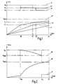
- Fig. 1 is a graph of a wear parameter V and a load limit parameter B of a component of a transmission over the mileage L in kilometers.
- the mileage L in the present context is synonymous with the service life or the mileage of the vehicle in which the transmission is installed.
- Fig. 1 is a mean mileage LE represented. This can be, for example, 100,000 kilometers, to refer to the example mentioned above.
- the mileage expectancy LE can also be, for example, 200,000 kilometers. It essentially depends on what average mileage expectancy the vehicle in which the transmission is installed is designed for.
- the wear parameter V and the load limit parameter B may relate to a part of a transmission, for example to a wheelset, to a single gear, to a shaft, or to a rotary bearing of the gearbox.
- the parameters may also relate to the transmission as a whole. This can be done, for example, by computational summary of the individual wear parameters of the relevant components of the transmission.
- the wear parameter of the transmission can also be easily aligned with the most wear-prone component of the transmission.
- the maximum load limit parameter B N is selected so that the maximum load on the gear unit is permitted, in accordance with the specification or the data sheet of the gear unit when the vehicle is delivered.
- the load on the transmission may be, for example, a value proportional to the maximum input torque of the transmission.
- the load limit parameter may simultaneously or alternatively be a value proportional to the maximum input speed of the transmission.
- the spin can also be included in the load limit parameter, if desired.
- the load limit parameter is reducible in two stages, to a value B 1 , which is smaller than B N , and to a value B 2 , which is smaller than B 1 .
- the maximum wear parameter V max is one such value of the wear parameter V that should be present at maximum when the average mileage expectancy LE is reached.
- the wear parameter V is a parameter which is continuously detected during the running performance L in the present embodiment of the method according to the invention.
- the wear parameter V may, for example, be represented as a value proportional to the number of rolling over of one of the gears of the wheelset. Further, the wear parameter V may be a value proportional to the torque transmitted through the gear. In the present embodiment, the wear parameter is determined by integrating the torque transmitted over the mileage. The wear parameters therefore include the number of overruns and the torque transmitted in each case.
- the wear parameter can be dimensioned, for example, based on the number of revolutions. The same applies if the transmission component is a pivot bearing. The number of revolutions over the mileage of the transmission is integrated.
- two threshold values V 1 and V 2 of the wear parameter are provided.
- the threshold value V 2 is smaller than the maximum wear parameter V max .
- the second threshold V 1 is less than the first threshold V 2 .
- Fig. 1 is the wear parameter V 'of a component of a transmission, which is installed in a vehicle that is driven by a very defensive driver. It can be seen that the wear parameter V 'does not reach the threshold value V 1 until the average mileage expectancy LE is reached. As a result, the assigned load limit parameter B 'for the entire mileage L remains at that until the average mileage expectancy LE is reached Maximum value B N. The defensive driver could thus overload the gear even before LE, according to the original specifications.
- Fig. 1 also shows a wear parameter V "associated with a component of a transmission installed in a vehicle operated by a driver that puts more load on the vehicle as a whole (for the sake of simplicity, this is referred to as” more powerful " Due to the driver's performance-enhancing driving style, the transmission component wears faster, which is reflected in a larger slope of the wear-parameter curve V ". As a result, the wear parameter V" already reaches the threshold value V 1 at a mileage d 1 "for example. about half the average running performance expectation LE may be. on the basis of the reaching of the threshold value V 1, the load limit parameter B" at d 1 '' to the value B 1 is reduced.
- V '' shows the wear parameter of a driver with a high level of performance, which means that the wear parameter V "'is even steeper right from the start.
- the threshold value V 1 is already reached at d 1 ''', a value which in the present case is about one third to one quarter of the mileage expectancy LE.
- the assigned load limit parameter becomes B '''reduced' wherein d 1 'B 1.
- the transmission component is thus charged is lower than at the beginning, which is reflected in a lower slope of the wear parameter curve.
- the wear parameter reaches V "already' at d 2 ''', ie before LE, the further threshold V 2 .
- the load limit parameter B "' is reduced from B 1 to B 2 at d 2 '", resulting in even further reduction of the maximum permissible load of the transmission component d 2 '''no longer so strong, which is reflected in an even lower slope of the wear parameter curve V''.
- the maximum wear parameter V MAX is not reached over the entire mileage when the average mileage expectancy LE is reached despite maximum power requirement by the driver.
- the method according to the invention consequently implements a regulation of the mileage expectation. Even if the transmission component is loaded above average from the beginning (as in V '''), by limiting the maximum load of the transmission component, it can be achieved that the mean running performance expectation LE is still achieved. As a result, the driver can no longer load the transmission component according to the maximum original specification as the mileage progresses. This can be expressed in the fact that despite full power requirement (for example, depressed accelerator pedal) not the full torque of the engine is provided. Thus, the maximum input torque can be reduced by the load limit parameter. Alternatively or additionally, the maximum speed can be limited.
- two threshold values V 1 , V 2 and correspondingly two levels of load limit parameters B 1 , B 2 are provided for the wear parameter. It is understood, however, that instead of only one threshold value V 1 can be provided. Alternatively, more than two threshold values of the wear parameter may be provided, with a corresponding increase in the number of stages of the reduction of the load limit parameter B.
- the wear parameter is shown schematically as a linear function. In practice, it will be understood that the wear parameter will gradually increase whenever a particular gear or wheel set is engaged for a particular gear ratio and thus claimed. In phases, however, in which this gear is not engaged, there is no or substantially no stress, so that the wear parameter remains substantially constant.
- the wear parameter is a value that increases with the mileage of the motor vehicle.
- the wear parameter for wheelsets / gears can also be distinguished between a wear parameter for the train operation and a wear parameter for the thrust operation. In this case, one would determine, for example, the torque transmitted in each case in the train operation by the position of a throttle flap of the motor of the motor vehicle or by a comparable signal.
- thrust mode in which the teeth of the gears of the wheelset are claimed in exactly the other direction, one could grasp the thrust moment, for example, via other known algorithms.
- Fig. 2 shows one of Fig. 1 Comparable diagram and represents a continuous control of a load limit parameter B IV on the basis of a wear parameter V IV , according to an alternative embodiment of the method according to the invention.
- the gear part is initially loaded relatively low (for example, by a defensive driver).
- d VK the vehicle is sold.
- the vehicle will be driven by a more powerful driver, so that the slope of the wear-parameter curve increases.
- the load limit parameter B IV is gradually lowered from d VK .
- the load by the driver is nevertheless so high that the load limit parameter B IV reaches a minimum value B min before reaching the average mileage expectancy LE.
- the value B min represents a state in which the load of the transmission is limited so that just a reasonable operation of the motor vehicle is possible. A further reduction of the load limit, however, would mean that the vehicle could no longer be adequately moved.
- the load limit parameter B IV remains at the value B min from the mileage d A.
- the wear parameter would only increase at a disproportionately low rate. If this is monitored by a suitable algorithm, then the lowering of the load limit parameter could be canceled again. This would mean that the defensive driver is at least once again given the opportunity to load the transmission to the maximum (eg in emergency situations).
- Fig. 3 shows a schematic representation of an automated drive train 10th
- the drive train 10 has an internal combustion engine 12, a starting and separating clutch 14 and an automated transmission 15.
- the gearbox 15 is equipped as a spur gear with a plurality of wheelsets 16, 18, 20, 22 corresponding to a plurality of gear stages.
- a first shift sleeve 24 serves to switch the wheelset 16 or the wheelset 18 alternatively.
- a second shift sleeve 26 serves to alternatively switch the wheelset 20 or the wheelset 22.
- the automated manual transmission 15 further includes a countershaft 28 and an output shaft 30 which are continuously connected via a constant gear 31.
- the countershaft 28 is supported by a plurality of pivot bearings (rolling bearings), one of which is shown at 32.
- the output shaft 30 is supported by a plurality of pivot bearings, one of which is shown schematically at 34.
- a controller 40 is shown.
- the control unit 40 is connected to both the internal combustion engine 12, the starting and separating clutch 14 and the automated manual transmission 15.
- the controller 40 may be constructed as a unitary controller. However, it may also be implemented so that decentralized control devices for the internal combustion engine 12 on the one hand and the automated transmission 15 (and possibly the clutch 14) are provided on the other hand and that a higher-level control unit is connected to these two decentralized control units.
- the control unit 40 detects the output rotational speed of the internal combustion engine 12 as well as the torque output by the internal combustion engine 12. It also provides a limit for each of these two variables.
- the control unit 40 also actuates the shift sleeves 24, 26 for engaging and disengaging gear stages of the gearbox 15.
- the control unit 40 "knows" accordingly the respective state of the gearbox 15th
- control process within the control unit 40 is schematically illustrated, which implements the inventive method.
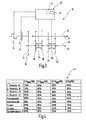
- a wear parameter is separately recorded for the gear parts and an assigned load limit parameter is set. These parameters are located in a register section 44 of the control unit 40.
- the register section 44 is in Fig. 4 shown schematically.
- Fig. 4 is shown that the wear parameter of each gear parts each already has an advanced value, namely in the range between 79 and 96%.
- the wear parameter V is given as a percentage value of the maximum wear parameter V max .
- the wear parameter of the first gearset 16 is 79%.
- the other wheelsets 18, 20, 22 have each wear parameters of 91%, 82% and 85% respectively.
- the wear parameter of the constant gear set 31 is higher (for example 89%).
- the inventive method according to the embodiment of the Fig. 1 is implemented with a first threshold V 1 and a second threshold V 2 .
- the threshold values V 1 , V 2 are also given as percentage values.
- the threshold value V 1 is 80% of the maximum wear parameter.
- the threshold value V 2 is 90% of the maximum wear parameter V max .
- the first set of wheels 16 has a wear parameter of 79%, which is therefore below V 1 .
- the assigned load limit parameter B is set to 100%.
- the load limit parameter B is in Fig. 4 also expressed as a percentage, based on the maximum load limit parameter B N.
- the second set of wheels 18 has been significantly more heavily loaded in the transmission.
- the wear parameter is 91% and thus already above V 2 .
- the load limit parameter is lowered to 85%.
- the third set of wheels and the fourth set of wheels are each between V 1 and V 2 , so that the load limit parameters are each 95%.
- thresholds V 1 , V 2 (to 80% or 90%) and the choice of lowering the load limit parameter 95% and 85% are merely exemplary.
- threshold values V 1 of 90% and V 2 of 95% are set.
- the steps B 2 , B 1 of the load limit parameter B are set to 95% and 90%.
- the wear parameters for the first countershaft 28 and the first bearing 32 are shown as separate values. In general, however, only one value of the wear parameter will be performed for both, since the number of revolutions for both components is usually decisive for the wear or the fatigue. The same naturally applies to the output shaft 30 and the associated bearing 34th
- the load limit parameter can be set individually. So it may be, for example, that the first set of wheels 16 at a certain time of mileage can still be charged to 100%, the second set of wheels 18, however, only 85%, as it is in Fig. 4 is shown.
- the controller 40 may still allow the maximum load at the input of the transmission 15, but limit the load when turning on the second gear set 18 (by limiting the torque and / or the input speed of the transmission 15).
- the shafts 28, 30 and bearings 32, 34 are generally loaded when transmitting power through the transmission 15, but not independently of the engaged gear ratio. Because the load on the shafts and bearings usually also depends on the gear that has been switched (other forces introduced from the loaded wheelsets result). Consequently, the maximum load of the transmission 15 depends on the transmission component, which already has the highest wear, in the case of Fig. 4 the constant gear set 31. There, the load limit parameter is set to 90%. This means that the load of the transmission 15 can generally be only 90%, regardless of the engaged gear.
- the first set of wheels 16 can still be loaded to 100%, even if the first set of wheels 16 is switched on, the maximum load of the transmission would be only 90%, because of the load limit parameter of the constant gear set 31.
- the shafts / bearings are always loaded. As mentioned above, however, the gear ratio selected also has a specific, although less influence on the load of the shaft / bearing.
- each calculated load limit parameter of each wheel set would be responsible for the maximum load of the transmission, since it is then assumed that the components constantly in the power flow can always be charged to 100%.
- the wear of the starting and separating clutch can be monitored in a corresponding manner. For example. by a wear parameter that is proportional to the integral of the transmitted torque multiplied by the respective slip, so that the wear is calculated.
- a wear parameter that is proportional to the integral of the transmitted torque multiplied by the respective slip, so that the wear is calculated.
- the wear parameter can be determined, for example, based on the speed and / or the transmitted torque (by integrating, as in the previous embodiments).
- the required variables for calculating the wear parameter are usually already present in a control unit.
- an additional sensor would have to be provided which detects which gear is engaged in each case and which torque is transmitted during this (or at what speed the gear is operated in each case).
Landscapes
- Engineering & Computer Science (AREA)
- Physics & Mathematics (AREA)
- General Physics & Mathematics (AREA)
- Automation & Control Theory (AREA)
- Transportation (AREA)
- Mechanical Engineering (AREA)
- Control Of Transmission Device (AREA)
Applications Claiming Priority (2)
| Application Number | Priority Date | Filing Date | Title |
|---|---|---|---|
| DE102004024840A DE102004024840B4 (de) | 2004-05-14 | 2004-05-14 | Verfahren zum Steuern eines automatisierten Kraftfahrzeug-Antriebsstranges |
| PCT/EP2005/004971 WO2005111948A2 (de) | 2004-05-14 | 2005-05-07 | Verfahren zum steuern eines automatisierten kraftfahrzeug-antriebsstranges und antriebsstrang |
Publications (2)
| Publication Number | Publication Date |
|---|---|
| EP1744934A2 EP1744934A2 (de) | 2007-01-24 |
| EP1744934B1 true EP1744934B1 (de) | 2008-07-30 |
Family
ID=35336107
Family Applications (1)
| Application Number | Title | Priority Date | Filing Date |
|---|---|---|---|
| EP05754343A Expired - Lifetime EP1744934B1 (de) | 2004-05-14 | 2005-05-07 | Verfahren zum steuern eines automatisierten kraftfahrzeug-antriebsstranges und antriebsstrang |
Country Status (6)
| Country | Link |
|---|---|
| US (1) | US7390283B2 (enExample) |
| EP (1) | EP1744934B1 (enExample) |
| JP (1) | JP4754558B2 (enExample) |
| CN (1) | CN100584664C (enExample) |
| DE (2) | DE102004024840B4 (enExample) |
| WO (1) | WO2005111948A2 (enExample) |
Cited By (1)
| Publication number | Priority date | Publication date | Assignee | Title |
|---|---|---|---|---|
| WO2023011831A1 (de) | 2021-08-04 | 2023-02-09 | Sew-Eurodrive Gmbh & Co. Kg | Verfahren und vorrichtung zur bestimmung der restlebensdauer eines getriebes |
Families Citing this family (13)
| Publication number | Priority date | Publication date | Assignee | Title |
|---|---|---|---|---|
| DE102007032946A1 (de) * | 2007-07-14 | 2009-01-15 | Zf Friedrichshafen Ag | Verfahren zur Steuerung einer automatisierten Trennkupplung |
| US20090099886A1 (en) * | 2007-10-12 | 2009-04-16 | Caterpillar Inc. | System and method for performance-based payload management |
| FR2931245B1 (fr) | 2008-05-16 | 2012-06-01 | Peugeot Citroen Automobiles Sa | Procede de construction d'un indicateur de fatigue, procedes de prevention et de maintenance utilisant cet indicateur, et dispositif pour la mise en oeuvre de ces procedes |
| WO2010147211A1 (ja) * | 2009-06-19 | 2010-12-23 | 日立建機株式会社 | 作業車両の制御装置 |
| EP2365215B1 (en) * | 2010-03-10 | 2012-12-12 | Siemens Aktiengesellschaft | Rotational speed control of a wind turbine based on rotor acceleration |
| DE102011006696A1 (de) * | 2011-04-04 | 2012-10-04 | Zf Friedrichshafen Ag | Leistungselektronikbaugruppe |
| EP3071866B1 (en) | 2013-11-19 | 2018-05-16 | Volvo Truck Corporation | Method to control an engine braking operation |
| US10408183B2 (en) | 2017-03-07 | 2019-09-10 | Ford Global Technologies, Llc | Methods and systems for improving engine starter durability for a stop/start vehicle |
| US10072626B1 (en) | 2017-03-07 | 2018-09-11 | Ford Global Technologies, Llc | Methods and systems for improving electric energy storage device durability for a stop/start vehicle |
| WO2020049525A2 (en) * | 2018-09-07 | 2020-03-12 | Bombardier Recreational Products Inc. | Method for estimating wear of a polymer drive belt of a continuously variable transmission |
| US20240019596A1 (en) * | 2022-07-12 | 2024-01-18 | Carrier Corporation | Audio-based occupancy detection |
| JP7670010B2 (ja) * | 2022-09-15 | 2025-04-30 | トヨタ自動車株式会社 | 情報処理装置、車両、情報処理システム、情報処理方法およびプログラム |
| CN116161039B (zh) * | 2023-03-27 | 2025-12-05 | 东风汽车集团股份有限公司 | 串并联混动汽车发动机轴瓦防磨损控制方法及系统 |
Family Cites Families (18)
| Publication number | Priority date | Publication date | Assignee | Title |
|---|---|---|---|---|
| DE3207938C2 (de) * | 1982-03-05 | 1986-08-07 | Zahnräderfabrik Renk AG, 8900 Augsburg | Unter Last schaltbare mechanische Getriebeanordnung |
| DE4100372A1 (de) * | 1991-01-09 | 1992-07-16 | Fichtel & Sachs Ag | Anordnung zur regelung des schlupfs einer automatisierten reibungskupplung |
| JPH0587220A (ja) * | 1991-09-27 | 1993-04-06 | Honda Motor Co Ltd | 自動変速機の制御装置 |
| DE4305172A1 (de) * | 1993-02-19 | 1994-08-25 | Autent Ingenieurgesellschaft F | Vorrichtung zur Überwachung eines sicherheitsrelevanten Elements eines Kraftfahrzeugs |
| JPH08128344A (ja) * | 1994-11-04 | 1996-05-21 | Hitachi Ltd | 駆動力制御装置及び制御方法 |
| US5588935A (en) * | 1995-09-29 | 1996-12-31 | Eaton Corporation | Throttle control for automated mechanical transmission |
| US5797110A (en) * | 1995-11-17 | 1998-08-18 | Eaton Corporation | Engine torque control |
| GB2315526B (en) | 1996-07-25 | 2001-02-14 | Luk Getriebe Systeme Gmbh | Method for the function monitoring of a motor vehicle gearbox and motor vehicle for use with the method |
| DE19740346A1 (de) * | 1997-09-13 | 1999-03-18 | Claas Selbstfahr Erntemasch | Selbstfahrende Arbeitsmaschine |
| DE19854366C1 (de) * | 1998-11-25 | 2000-04-06 | Daimler Chrysler Ag | Verfahren zur Anpassung einer Auslöseschwelle von Insassenschutzeinrichtungen |
| DE10035005B4 (de) * | 1999-08-02 | 2009-08-20 | Luk Lamellen Und Kupplungsbau Beteiligungs Kg | Verfahren und Vorrichtung zur Regelung der Übersetzung eines Getriebes mit stufenlos veränderbarer Übersetzung |
| DE10007308A1 (de) | 2000-02-17 | 2001-08-23 | Bosch Gmbh Robert | Verfahren und Vorrichtung zur Ermittlung der verbleibenden Betriebsdauer eines Produktes |
| DE10161998A1 (de) | 2001-12-18 | 2003-07-17 | Daimler Chrysler Ag | Verfahren und Vorrichtung zur Betriebsüberwachung |
| DE20120609U1 (de) * | 2001-12-20 | 2002-03-21 | Beck IPC GmbH, 35578 Wetzlar | Diagnoseeinrichtung für eine fluidtechnische Einrichtung sowie damit ausgestattete fluidtechnische Einrichtung |
| DE10211130A1 (de) * | 2002-03-14 | 2003-09-25 | Zahnradfabrik Friedrichshafen | Verfahren zur Optimierung der Lebensdauer von Komponenten und/oder Bauteilen eines Kraftfahrzeugs |
| BE1015026A3 (nl) * | 2002-07-17 | 2004-08-03 | Ipso Lsg Nv | Droogkast met roteerbare droogtrommel. |
| DE50213449D1 (de) * | 2002-08-09 | 2009-05-28 | Ford Global Tech Llc | Vorrichtung und Verfahren zur Leistungssteigerung einer Brennkraftmaschine |
| DE10254819A1 (de) * | 2002-11-25 | 2004-06-09 | Robert Bosch Gmbh | Grenzlastabhängiges teilweises Abschalten einzelner Funktionen der Systemkomponenten eines Fahrzeugs |
-
2004
- 2004-05-14 DE DE102004024840A patent/DE102004024840B4/de not_active Expired - Fee Related
-
2005
- 2005-05-07 JP JP2007512049A patent/JP4754558B2/ja not_active Expired - Fee Related
- 2005-05-07 CN CN200580015509.2A patent/CN100584664C/zh not_active Expired - Fee Related
- 2005-05-07 EP EP05754343A patent/EP1744934B1/de not_active Expired - Lifetime
- 2005-05-07 DE DE502005004895T patent/DE502005004895D1/de not_active Expired - Lifetime
- 2005-05-07 WO PCT/EP2005/004971 patent/WO2005111948A2/de not_active Ceased
-
2006
- 2006-11-10 US US11/598,218 patent/US7390283B2/en not_active Expired - Fee Related
Cited By (2)
| Publication number | Priority date | Publication date | Assignee | Title |
|---|---|---|---|---|
| WO2023011831A1 (de) | 2021-08-04 | 2023-02-09 | Sew-Eurodrive Gmbh & Co. Kg | Verfahren und vorrichtung zur bestimmung der restlebensdauer eines getriebes |
| DE102022002464A1 (de) | 2021-08-04 | 2023-02-09 | Sew-Eurodrive Gmbh & Co Kg | Verfahren und Vorrichtung zur Bestimmung der Restlebensdauer eines Getriebes |
Also Published As
| Publication number | Publication date |
|---|---|
| DE102004024840A1 (de) | 2005-12-08 |
| US7390283B2 (en) | 2008-06-24 |
| CN101022975A (zh) | 2007-08-22 |
| JP4754558B2 (ja) | 2011-08-24 |
| WO2005111948A3 (de) | 2006-07-13 |
| JP2007537405A (ja) | 2007-12-20 |
| DE502005004895D1 (enExample) | 2008-09-11 |
| CN100584664C (zh) | 2010-01-27 |
| US20070167282A1 (en) | 2007-07-19 |
| WO2005111948A2 (de) | 2005-11-24 |
| EP1744934A2 (de) | 2007-01-24 |
| DE102004024840B4 (de) | 2007-02-22 |
Similar Documents
| Publication | Publication Date | Title |
|---|---|---|
| EP2094552B1 (de) | Verfahren zur durchführung eines gangwechsels eines automatisierten schaltgetriebes | |
| EP1744934B1 (de) | Verfahren zum steuern eines automatisierten kraftfahrzeug-antriebsstranges und antriebsstrang | |
| EP3468826B1 (de) | Hydraulisches kupplungsbetätigungssystem mit on-demand kupplungsbeölung | |
| DE102009005378A1 (de) | Antriebsstrang für ein Kraftfahrzeug | |
| WO2000035697A2 (de) | Rückschaltsicherheit für kraftfahrzeug | |
| EP2063152A1 (de) | Verfahren zum Schalten eines Doppelkupplungsgetriebes | |
| EP1564446B1 (de) | Verfahren und Vorrichtung zum Steuern eines Gangwechsels in einem Parallelschaltgetriebe eines Fahrzeuges | |
| WO2001006152A1 (de) | Temperaturabhängige steurungsvorrichtung einer kupplung oder eines fahrzeuggetriebes | |
| WO2000075536A1 (de) | Verfahren zum betreiben einer betätigungseinrichtung eines automatisierten schaltgetriebes | |
| DE69802139T2 (de) | Bestimmung der Kupplungseinstellung | |
| EP2019768A1 (de) | Verfahren und vorrichtung zur steuerung eines automatisierten schaltgetriebes | |
| WO2010097244A2 (de) | Verfahren zur steuerung der kühlmittelzufuhr und der schmiermittelzufuhr einer kupplung eines kraftfahrzeuges mit einem automatischen schaltgetriebe | |
| DE102013216142A1 (de) | Verfahren zur Regelung eines Gangwechsels bei einem automatisierten Kraftfahrzeuggetriebe | |
| EP2100050A1 (de) | Verfahren zum steuern einer reibungskupplung eines fahrzeuges | |
| EP0849505A2 (de) | Verfahren und Vorrichtung zur Früherkennung von Störfällen beim Betrieb automatischer Getriebe | |
| EP3760889B1 (de) | Antriebsstrang eines fahrzeugs sowie verfahren zum betreiben eines antriebsstrangs eines fahrzeugs | |
| EP1632694B1 (de) | Antriebsstrang mit Parallelschaltgetriebe | |
| DE102011006386B4 (de) | Verfahren zur Freigabe einer Rückschaltung in einem automatischen Fahrzeuggetriebe | |
| EP0892895A1 (de) | Steuerung, insbesondere notsteuerung, einer automatischen kupplung | |
| EP1859326B1 (de) | Verfahren zur steuerung eines ansteuerbaren aggregats | |
| DE102005037751B4 (de) | Antrieb für ein Mobilfahrzeug | |
| DE102017220031B4 (de) | Verfahren zum Betreiben eines hydrostatisch-mechanischen Leistungsverzweigungsgetriebes sowie ein hydrostatisch-mechanisches Leistungsverzweigungsgetriebe | |
| EP1509710A1 (de) | Automatisiertes schaltgetriebe sowie verfahren zum betreiben einer getriebeeinrichtung | |
| DE102021209152B3 (de) | Verfahren zur Steuerung eines Schaltvorganges | |
| EP3461708A1 (de) | Antriebsanordnung für ein schienenfahrzeug und antriebsstrang |
Legal Events
| Date | Code | Title | Description |
|---|---|---|---|
| PUAI | Public reference made under article 153(3) epc to a published international application that has entered the european phase |
Free format text: ORIGINAL CODE: 0009012 |
|
| 17P | Request for examination filed |
Effective date: 20061020 |
|
| AK | Designated contracting states |
Kind code of ref document: A2 Designated state(s): AT BE BG CH CY CZ DE DK EE ES FI FR GB GR HU IE IS IT LI LT LU MC NL PL PT RO SE SI SK TR |
|
| AX | Request for extension of the european patent |
Extension state: AL BA HR LV MK YU |
|
| 17Q | First examination report despatched |
Effective date: 20070308 |
|
| DAX | Request for extension of the european patent (deleted) | ||
| RBV | Designated contracting states (corrected) |
Designated state(s): DE FR IT |
|
| GRAP | Despatch of communication of intention to grant a patent |
Free format text: ORIGINAL CODE: EPIDOSNIGR1 |
|
| RBV | Designated contracting states (corrected) |
Designated state(s): DE FR IT |
|
| GRAS | Grant fee paid |
Free format text: ORIGINAL CODE: EPIDOSNIGR3 |
|
| GRAA | (expected) grant |
Free format text: ORIGINAL CODE: 0009210 |
|
| AK | Designated contracting states |
Kind code of ref document: B1 Designated state(s): DE FR IT |
|
| REF | Corresponds to: |
Ref document number: 502005004895 Country of ref document: DE Date of ref document: 20080911 Kind code of ref document: P |
|
| PLBE | No opposition filed within time limit |
Free format text: ORIGINAL CODE: 0009261 |
|
| STAA | Information on the status of an ep patent application or granted ep patent |
Free format text: STATUS: NO OPPOSITION FILED WITHIN TIME LIMIT |
|
| 26N | No opposition filed |
Effective date: 20090506 |
|
| PGFP | Annual fee paid to national office [announced via postgrant information from national office to epo] |
Ref country code: FR Payment date: 20110607 Year of fee payment: 7 |
|
| PGFP | Annual fee paid to national office [announced via postgrant information from national office to epo] |
Ref country code: IT Payment date: 20110523 Year of fee payment: 7 |
|
| PGFP | Annual fee paid to national office [announced via postgrant information from national office to epo] |
Ref country code: DE Payment date: 20110628 Year of fee payment: 7 |
|
| PG25 | Lapsed in a contracting state [announced via postgrant information from national office to epo] |
Ref country code: IT Free format text: LAPSE BECAUSE OF NON-PAYMENT OF DUE FEES Effective date: 20120507 |
|
| REG | Reference to a national code |
Ref country code: FR Ref legal event code: ST Effective date: 20130131 |
|
| REG | Reference to a national code |
Ref country code: DE Ref legal event code: R119 Ref document number: 502005004895 Country of ref document: DE Effective date: 20121201 |
|
| PG25 | Lapsed in a contracting state [announced via postgrant information from national office to epo] |
Ref country code: FR Free format text: LAPSE BECAUSE OF NON-PAYMENT OF DUE FEES Effective date: 20120531 |
|
| PG25 | Lapsed in a contracting state [announced via postgrant information from national office to epo] |
Ref country code: DE Free format text: LAPSE BECAUSE OF NON-PAYMENT OF DUE FEES Effective date: 20121201 |