EP1744656B1 - Korbhebeanordnung für eine geschirrspülmaschine - Google Patents
Korbhebeanordnung für eine geschirrspülmaschine Download PDFInfo
- Publication number
- EP1744656B1 EP1744656B1 EP05728313A EP05728313A EP1744656B1 EP 1744656 B1 EP1744656 B1 EP 1744656B1 EP 05728313 A EP05728313 A EP 05728313A EP 05728313 A EP05728313 A EP 05728313A EP 1744656 B1 EP1744656 B1 EP 1744656B1
- Authority
- EP
- European Patent Office
- Prior art keywords
- dishwasher
- basket
- door
- dishwasher according
- cabinet
- Prior art date
- Legal status (The legal status is an assumption and is not a legal conclusion. Google has not performed a legal analysis and makes no representation as to the accuracy of the status listed.)
- Not-in-force
Links
- 239000007788 liquid Substances 0.000 description 3
- 230000000630 rising effect Effects 0.000 description 2
- 230000003213 activating effect Effects 0.000 description 1
- 238000005452 bending Methods 0.000 description 1
- 238000004140 cleaning Methods 0.000 description 1
- 238000004804 winding Methods 0.000 description 1
Images

Classifications
-
- A—HUMAN NECESSITIES
- A47—FURNITURE; DOMESTIC ARTICLES OR APPLIANCES; COFFEE MILLS; SPICE MILLS; SUCTION CLEANERS IN GENERAL
- A47L—DOMESTIC WASHING OR CLEANING; SUCTION CLEANERS IN GENERAL
- A47L15/00—Washing or rinsing machines for crockery or tableware
- A47L15/42—Details
- A47L15/50—Racks ; Baskets
- A47L15/506—Arrangements for lifting racks for loading or unloading purposes
Definitions
- This invention relates to a dishwasher comprising a wash cabinet having a bottom, two opposite side walls , an upper and a rear wall and an opening that normally is covered by a front door the dishwasher being provided with at least one lower basket for the dish being cleaned, said basket being movable between a first position inside the cabinet and a second position mainly outside the cabinet, the dishwasher at each side of the opening being provided with a support arranged to move mainly vertically in or close to the side walls for raising the lower basket from a lower to an upper position and vice versa
- Household dishwashers of the floor standing type having means for lifting the lower basket in order to make it easier to load or unload the basket are previously known in the art.
- the major part of such known devices are provided with torque link arrangements, see for instance US 5115822 , arrangements for lifting the door together with the basket, see US 6510858 , or manually operated swing arm systems, see JP 10-179495 .
- These arrangements have however proved to be unsatisfactory with regard to stability and safety and moreover the arrangements are rather complicated and hence expensive.
- It is also previously known to provide a dishwasher with a height adjustment mechanism for an intermediate basket that is placed between a lower and an upper basket see US 2003/0042825 .
- This mechanism is provided with means at each side for supporting the guide rails on which the basket rests.
- the arrangement is primarily intended for adjusting the space above or below the intermediate basket in order to make it possible to wash details having different sizes and the arrangement has a limited vertical movement possibility.
- the purpose of this invention is to create an ergonomic lifting arrangement for a lower dishwasher basket making it possible for the operator to easily pick out the dish from the basket without the need for bending his back.
- An additional purpose is to create an arrangement that is stable and safe to use as well as simple and reliable. This is achieved by means of an arrangement having the characteristics mentioned in the claims.
- FIG. 1 schematically shows a perspective view of a dishwasher with the lower basket in a lower position
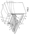
- Fig. 2 is a perspective view of the dishwasher with the lower basket in a lifted up position
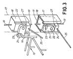
- Fig. 3 is a partly broken perspective view showing a part of the lifting mechanism in two different positions.
- the dishwasher comprises a wash cabinet 10 provided with a bottom, two side walls 11, an upper and a rear wall and an opening that normally is covered by a front door 12.
- An upper and a lower basket 13 (upper basket not shown) are provided in the cabinet and the baskets can be pulled out from their position within the cabinet to a position outside the cabinet.
- the dishwasher is in a conventional way also provided with rotating wash arms, filter means, a circulation pump, an outlet pump and mechanical and electrical control means for distributing cleaning liquid into the cabinet as well as to circulate the liquid in the cabinet in order to clean the dish which is placed on the baskets before the liquid is emptied from the cabinet.
- the lastmentioned means are however not shown and described in detail since they are not a part of the present invention.
- the lower basket 13 which is provided with several rolls 14 can be pulled out from the cabinet 10 by the operator such that the wheels are guided in elongated recesses 15 arranged on the inner side of the door 12 when the door is in a folded down, mainly horizontal position.
- the lower basket 13 is at its innermost end and at each side provided with a U-shaped catch portion 16 the purpose of which will be explained below.
- Each side walls 11 is at its front part provided with a C-shaped rail 17 extending almost from the bottom of the cabinet to its top and in which a slider 18 is guided for vertical motion.
- the slider can be raised and lowered by means of a wire 19 that via pulleys (not shown) mounted in the side walls are connected to a an electric motor (not shown) that can be activated by a control means 20.
- a switch At each end of at least one of the rails 17 there is a switch (not shown) stopping the upwards or downwards movement of the slider 18.
- the slider 18 is at its front side provided with a support such as spring loaded arm 21 that can be turned about an axis 22 and having a hook 23.
- the arm can be turned from an upright position, see the lower part of Fig. 3 , in which it the arm rests against a forwardly extending flange portion 24 of the rail 17 to a folded out position, see the upper part of Fig. 3 , in which the arm rests against a shoulder 25 of the slider 18.
- the dishwasher is further provided with two wires 25 each having one end secured to one of the sliders 18 whereas the other end is secured to a spring (not shown) arranged within the door 12.
- the wires 25 run freely through an aperture 26 at the side edges of the door 12 and are under the influence of the spring but the pull out motion of the wires from the door is restricted by a separate stop member (not shown), secured to the wire inside the door, or the spring and engaging the door wall when the wires have been pulled out to their end positions.
- the arrangement operates in the following manner.
- the operator pulls out the lower basket 13 from the cabinet 10 and the rolls 14 are thus running in the elongated recesses 15 on the door 12.
- the operator pushes the control means 20 such that the electric motor of the winding arrangement is started which means that the wires 19 simultaneously lift the sliders 18 from their lower position illustrated in the bottom of Fig. 3 to a somewhat raised position shown in the upper part of the same figure.
- the arms 21 Because of the spring forces acting on the arms 21 and the successive rising motion above the upper end of the flanges 24 the arms gradually are turned and finally reach their folded out positions in which the arms rest on the shoulders 27 of the sliders 18. Further rising motion of the slides 18 means that the hooks 23 arranged on the arms 21 move into the catch portions 16 of the basket 13 and start to lift the inner end of the basket.
- the wires 25 are gradually pulled out from the door 12 through the aperture depending on the wire interconnection with the sliders 18 until the stop member on the wire engages the inside wall of the door. Then the door starts to turn upwards at the same time as the front rollers 14 start to roll upwards in the recesses 15.
- continued raising of the sliders 18 means that the basket is gradually lifted.
- the switches will stop the electric motor and hence the basket will now be in a lifted up position such that it is easy to pick out the dish. Lowering the basket will take place in the reverse order after activating the control means 20.
Claims (10)
- Geschirrspüler, umfassend einen Spülbehälter (10) mit einem Boden, zwei gegenüber angeordneten Wänden (11), einer oberen und Rückwand und einer Öffnung, die normalerweise mit einer Fronttür (12) bedeckt ist, wobei der Geschirrspüler mit mindestens einem Unterkorb (13) für das zu reinigende Geschirr ausgestattet ist, der zwischen einer ersten Position im Behälter und einer zweiten Position hauptsächlich außerhalb des Behälters beweglich ist, wobei der Geschirrspüler auf jeder Seite der Öffnung mit einer Halterung (21) versehen ist, die so angeordnet ist, dass sie sich hauptsächlich senkrecht in den oder nahe der Seitenwände (11) bewegt, um den Unterkorb (13) von einer unteren in eine obere Position und umgekehrt zu bewegen, dadurch gekennzeichnet, dass die Halterungen (21) von einem Hubmittel (18) beeinflusst werden, das so angeordnet ist, dass es die Halterungen von einer inaktiven Position ohne Verbindung mit dem Unterkorb (13) in eine aktive Position bewegen, in der sie mit dem Unterkorb verbunden sind.
- Geschirrspüler gemäß Anspruch 1, dadurch gekennzeichnet, dass die Halterung (21) ein schwenkbarer oder ausfahrbarer Arm ist.
- Geschirrspüler gemäß Anspruch 1 oder 2, dadurch gekennzeichnet, dass das Hubmittel (18) durch einen Elektromotor aktiviert wird, der an ein Steuermittel (20) angeschlossen ist.
- Geschirrspüler gemäß Anspruch 3, dadurch gekennzeichnet, dass der Elektromotor über ein Leitersystem (19) mit dem Hubmittel (18) verbunden ist.
- Geschirrspüler gemäß einem beliebigen der vorangehenden Ansprüche, dadurch gekennzeichnet, dass das Hubmittel (18) einen Schieber umfasst, der über eine Schiene (17) hauptsächlich senkrecht geführt wird.
- Geschirrspüler gemäß einem beliebigen der vorangehenden Ansprüche, dadurch gekennzeichnet, dass der Geschirrspüler ferner einen Türdrehmechanismus umfasst, der die Hubbewegung der Halterungen mit der Türschwenkbewegung auf eine Weise synchronisiert, dass der Korb von den Halterungen (21) sowie von der Tür (12) gehalten wird.
- Geschirrspüler gemäß Anspruch 6, dadurch gekennzeichnet, dass die Tür mit dem Hubmittel über eine mechanische Verbindung verbunden ist.
- Geschirrspüler gemäß Anspruch 7, dadurch gekennzeichnet, dass die mechanische Verbindung ein Draht (25) ist.
- Geschirrspüler gemäß Anspruch 8, dadurch gekennzeichnet, dass die Tür mit einer Öffnung (26) versehen ist, durch die der Draht (25) in die Tür geführt wird, und dass das Ende des Drahtes in der Tür mit einer Feder verbunden ist.
- Geschirrspüler gemäß Anspruch 2, dadurch gekennzeichnet, dass der Arm (21) federgespannt ist und mit einem Flansch (24) oder dergleichen zusammenwirkt, der den Arm von einer waagrechten in eine senkrechte Position schwenkt, wenn das Hubmittel (18) seine untere Position erreicht.
Priority Applications (1)
| Application Number | Priority Date | Filing Date | Title |
|---|---|---|---|
| PL05728313T PL1744656T3 (pl) | 2004-04-29 | 2005-04-07 | Układ podnoszenia kosza w zmywarce |
Applications Claiming Priority (2)
| Application Number | Priority Date | Filing Date | Title |
|---|---|---|---|
| SE0401122A SE0401122D0 (sv) | 2004-04-29 | 2004-04-29 | Basket lifting arrangement for a dishwasher |
| PCT/SE2005/000515 WO2005104924A1 (en) | 2004-04-29 | 2005-04-07 | Basket lifting arrangement for a dishwasher |
Publications (2)
| Publication Number | Publication Date |
|---|---|
| EP1744656A1 EP1744656A1 (de) | 2007-01-24 |
| EP1744656B1 true EP1744656B1 (de) | 2009-03-11 |
Family
ID=32322715
Family Applications (1)
| Application Number | Title | Priority Date | Filing Date |
|---|---|---|---|
| EP05728313A Not-in-force EP1744656B1 (de) | 2004-04-29 | 2005-04-07 | Korbhebeanordnung für eine geschirrspülmaschine |
Country Status (9)
| Country | Link |
|---|---|
| US (1) | US8162419B2 (de) |
| EP (1) | EP1744656B1 (de) |
| AT (1) | ATE424753T1 (de) |
| AU (1) | AU2005237388B2 (de) |
| DE (1) | DE602005013203D1 (de) |
| NZ (1) | NZ550833A (de) |
| PL (1) | PL1744656T3 (de) |
| SE (1) | SE0401122D0 (de) |
| WO (1) | WO2005104924A1 (de) |
Cited By (3)
| Publication number | Priority date | Publication date | Assignee | Title |
|---|---|---|---|---|
| US9282877B2 (en) | 2012-03-21 | 2016-03-15 | Whirlpool Corporation | Dishwasher with a pivot system for a dish rack |
| DE102017213699A1 (de) | 2017-08-07 | 2019-02-07 | BSH Hausgeräte GmbH | Haushaltsgeschirrspülmaschine |
| DE102019220265A1 (de) * | 2019-12-19 | 2021-06-24 | BSH Hausgeräte GmbH | Haushalts-Geschirrspülmaschine |
Families Citing this family (39)
| Publication number | Priority date | Publication date | Assignee | Title |
|---|---|---|---|---|
| US8813766B2 (en) | 2011-05-18 | 2014-08-26 | Whirlpool Corporation | Height adjuster mechanism for a dishwasher dish rack |
| US9596975B2 (en) | 2011-05-18 | 2017-03-21 | Whirlpool Corporation | Height adjuster mechanism for a dishwasher dish rack |
| US9004082B2 (en) | 2011-05-18 | 2015-04-14 | Whirlpool Corporation | Dish rack height adjusting employing cam and follower mechanism |
| US8900375B2 (en) * | 2011-09-15 | 2014-12-02 | General Electric Company | Two level conduit docking port mechanism for a dishwashing appliance |
| USD694966S1 (en) * | 2012-04-11 | 2013-12-03 | Electrolux Home Products Corporation N.V. | Laundry appliance |
| KR101961373B1 (ko) | 2012-11-19 | 2019-03-22 | 엘지전자 주식회사 | 식기세척기 |
| KR102002505B1 (ko) * | 2012-11-19 | 2019-07-22 | 엘지전자 주식회사 | 식기세척기 |
| KR102002419B1 (ko) * | 2013-06-27 | 2019-07-23 | 삼성전자주식회사 | 식기세척기 |
| DE102013226910A1 (de) | 2013-12-20 | 2015-06-25 | BSH Hausgeräte GmbH | Hebevorrichtung und wasserführendes Haushaltsgerät |
| FR3018677B1 (fr) * | 2014-03-18 | 2016-04-15 | Jacques Valdenaire | Dispositif de caisson avec systeme de levage pour appareil electromenager tel que lave-vaisselle ou pour meuble a tiroir. |
| WO2015154906A1 (en) | 2014-04-08 | 2015-10-15 | Arcelik Anonim Sirketi | A dishwasher comprising an elevating means |
| WO2015165606A1 (en) * | 2014-04-30 | 2015-11-05 | Arcelik Anonim Sirketi | A dishwasher comprising an elevating means |
| WO2015185228A1 (en) * | 2014-06-02 | 2015-12-10 | Arcelik Anonim Sirketi | A dishwasher comprising an elevating means |
| EP3151715B8 (de) * | 2014-06-05 | 2019-07-17 | Arçelik Anonim Sirketi | Geschirrspüler mit hebevorrichtung |
| EP3151716B1 (de) | 2014-06-05 | 2020-03-04 | Arçelik Anonim Sirketi | Geschirrspüler mit hebevorrichtung |
| EP3151717B1 (de) | 2014-06-06 | 2019-02-13 | Arçelik Anonim Sirketi | Geschirrspüler mit hebevorrichtung |
| CA2958307C (en) * | 2014-08-25 | 2022-12-13 | Rolls-Royce Energy Systems Inc. | Gas turbine engine package and corresponding method |
| DE102014226820A1 (de) | 2014-12-22 | 2016-06-23 | BSH Hausgeräte GmbH | Unterkorb für eine Haushaltsgeschirrspülmaschine mit Unterkorb-Anhebung |
| EP3085294A1 (de) | 2015-04-24 | 2016-10-26 | BSH Hausgeräte GmbH | Hebevorrichtung und geschirrspülmaschine |
| DE102015211362A1 (de) | 2015-06-19 | 2016-12-22 | BSH Hausgeräte GmbH | Hebevorrichtung und Geschirrspülmaschine |
| DE102015208661A1 (de) | 2015-05-11 | 2016-11-17 | BSH Hausgeräte GmbH | Geschirrspülmaschine |
| DE102015211492B4 (de) | 2015-06-22 | 2017-12-14 | BSH Hausgeräte GmbH | Hebevorrichtung und Geschirrspülmaschine |
| DE102015211495B4 (de) | 2015-06-22 | 2017-12-14 | BSH Hausgeräte GmbH | Hebevorrichtung und Geschirrspülmaschine |
| ES2613047B1 (es) * | 2015-11-19 | 2018-02-27 | Bsh Electrodomésticos España, S.A. | Dispositivo de elevación y máquina lavavajillas. |
| US10080479B2 (en) | 2016-01-18 | 2018-09-25 | Haier Us Appliance Solutions, Inc. | Lower rack assembly for dishwasher appliance |
| US10231599B2 (en) | 2016-03-28 | 2019-03-19 | Haier Us Appliance Solutions, Inc. | Lower rack assembly for dishwasher appliance |
| US10159398B2 (en) | 2016-12-27 | 2018-12-25 | Midea Group Co., Ltd. | Dishwasher rack system |
| US9895046B1 (en) * | 2016-12-27 | 2018-02-20 | Midea Group Co., Ltd. | Dishwasher rack lift system |
| US10702125B2 (en) | 2017-09-29 | 2020-07-07 | Midea Group Co., Ltd. | Retracting dishwasher rack system |
| CN108403055B (zh) * | 2018-05-09 | 2024-03-26 | 火星人厨具股份有限公司 | 一种厨具的可升降碗篮 |
| EP3801181A1 (de) | 2018-05-25 | 2021-04-14 | Arçelik Anonim Sirketi | Geschirrspülmaschine mit einem beweglichen korb |
| USD907867S1 (en) * | 2018-09-17 | 2021-01-12 | Lg Electronics Inc. | Dishwasher |
| USD929683S1 (en) * | 2018-09-17 | 2021-08-31 | Lg Electronics Inc. | Dishwasher |
| US10694923B1 (en) | 2018-12-10 | 2020-06-30 | Midea Group Co., Ltd. | Retracting dishwasher rack system |
| US10582828B1 (en) * | 2018-12-10 | 2020-03-10 | Midea Group Co., Ltd. | Retracting dishwasher rack system |
| US11219350B2 (en) | 2018-12-10 | 2022-01-11 | Midea Group Co., Ltd. | Retracting dishwasher rack system |
| DE102019215312A1 (de) | 2019-10-07 | 2021-04-08 | BSH Hausgeräte GmbH | Haushaltsgeschirrspülmaschine |
| CN111227759B (zh) * | 2020-02-24 | 2021-11-09 | 佛山市顺德区美的洗涤电器制造有限公司 | 洗碗机及其碗篮装置 |
| DE102020208346A1 (de) * | 2020-07-03 | 2022-01-05 | BSH Hausgeräte GmbH | System mit einer Geschirrspülmaschine und Verfahren zum Betreiben einer Geschirrspülmaschine |
Family Cites Families (19)
| Publication number | Priority date | Publication date | Assignee | Title |
|---|---|---|---|---|
| US3321261A (en) * | 1965-04-22 | 1967-05-23 | Gen Electric | Rack system for automatic dishwasher |
| US3472573A (en) * | 1967-12-11 | 1969-10-14 | Hobart Corp | Rack system for dishwashing machine |
| US3466108A (en) * | 1967-12-21 | 1969-09-09 | Gen Electric | Door-operated rack extending and retracting means for a front-opening appliance cabinet |
| US3736037A (en) * | 1971-06-01 | 1973-05-29 | Gen Electric | Rack level adjustment apparatus in an appliance cabinet |
| US3726580A (en) * | 1971-06-01 | 1973-04-10 | Gen Electric | Rack level adjustment apparatus in an appliance cabinet |
| US3761153A (en) * | 1971-06-17 | 1973-09-25 | Gen Electric | Dish-washing machine rack adjustment assembly |
| US3822085A (en) * | 1971-12-27 | 1974-07-02 | Gen Electric | Dishwashing machine rack level adjustment system |
| US3768883A (en) * | 1971-12-27 | 1973-10-30 | Gen Electric | Rack level adjustment system in a dishwasher |
| US3794400A (en) * | 1972-06-26 | 1974-02-26 | Gen Electric | Rack mechanism for toploading dishwasher |
| US5115822A (en) * | 1991-03-20 | 1992-05-26 | Nichols Will E | Dishwasher basket assembly including lift mechanism |
| US5226706A (en) * | 1991-12-09 | 1993-07-13 | Maytag Corporation | Adjustable door balancing mechanism |
| IT235034Y1 (it) * | 1994-07-15 | 2000-03-31 | Zanussi Elettrodomestici | Lavastoviglie con cesto regolabile in altezza |
| DE19611050B4 (de) * | 1996-03-20 | 2008-09-18 | BSH Bosch und Siemens Hausgeräte GmbH | Vorrichtung zum Gewichtsausgleich einer frontseitigen, um eine horizontale Achse schwenkbaren, an einem Gehäuse gelagerten Tür eines Haushaltgerätes, insbesondere einer Haushalt-Geschirrspülmaschine |
| JPH10179495A (ja) | 1996-12-26 | 1998-07-07 | Matsushita Electric Ind Co Ltd | 食器洗い機 |
| US5971513A (en) * | 1998-03-19 | 1999-10-26 | Cassalia; Alan B. | Easy load extendable/retractable bottom dishwasher rack |
| US5896703A (en) * | 1998-06-26 | 1999-04-27 | General Motors Corporation | Power liftgate cable drive |
| US6510858B1 (en) * | 2000-08-09 | 2003-01-28 | Steris Inc. | Load lifting/lowering mechanism for a washer |
| US6247771B1 (en) * | 2000-08-18 | 2001-06-19 | Evelyn J. Miller | Lower rack lifting device for a dishwasher |
| US6755490B2 (en) * | 2001-08-30 | 2004-06-29 | Maytag Corporation | Dishwasher with adjustable rack |
-
2004
- 2004-04-29 SE SE0401122A patent/SE0401122D0/xx unknown
-
2005
- 2005-04-07 WO PCT/SE2005/000515 patent/WO2005104924A1/en active Application Filing
- 2005-04-07 EP EP05728313A patent/EP1744656B1/de not_active Not-in-force
- 2005-04-07 US US11/568,262 patent/US8162419B2/en not_active Expired - Fee Related
- 2005-04-07 AU AU2005237388A patent/AU2005237388B2/en not_active Ceased
- 2005-04-07 NZ NZ550833A patent/NZ550833A/en not_active IP Right Cessation
- 2005-04-07 AT AT05728313T patent/ATE424753T1/de not_active IP Right Cessation
- 2005-04-07 DE DE602005013203T patent/DE602005013203D1/de active Active
- 2005-04-07 PL PL05728313T patent/PL1744656T3/pl unknown
Cited By (7)
| Publication number | Priority date | Publication date | Assignee | Title |
|---|---|---|---|---|
| US9282877B2 (en) | 2012-03-21 | 2016-03-15 | Whirlpool Corporation | Dishwasher with a pivot system for a dish rack |
| US10123677B2 (en) | 2012-03-21 | 2018-11-13 | Whirlpool Corporation | Dishwasher with a pivot system for a dish rack |
| US10178938B2 (en) | 2012-03-21 | 2019-01-15 | Whirpool Corporation | Dishwasher with a pivot system for a dish rack |
| US11116380B2 (en) | 2012-03-21 | 2021-09-14 | Whirlpool Corporation | Dishwasher with a pivot system for a dish rack |
| DE102017213699A1 (de) | 2017-08-07 | 2019-02-07 | BSH Hausgeräte GmbH | Haushaltsgeschirrspülmaschine |
| DE102019220265A1 (de) * | 2019-12-19 | 2021-06-24 | BSH Hausgeräte GmbH | Haushalts-Geschirrspülmaschine |
| DE102019220265B4 (de) | 2019-12-19 | 2021-10-21 | BSH Hausgeräte GmbH | Haushalts-Geschirrspülmaschine mit einer beweglichen Bedieneinrichtung |
Also Published As
| Publication number | Publication date |
|---|---|
| NZ550833A (en) | 2009-10-30 |
| EP1744656A1 (de) | 2007-01-24 |
| US8162419B2 (en) | 2012-04-24 |
| AU2005237388B2 (en) | 2010-07-22 |
| AU2005237388A1 (en) | 2005-11-10 |
| DE602005013203D1 (de) | 2009-04-23 |
| PL1744656T3 (pl) | 2009-08-31 |
| WO2005104924A1 (en) | 2005-11-10 |
| ATE424753T1 (de) | 2009-03-15 |
| US20090009040A1 (en) | 2009-01-08 |
| SE0401122D0 (sv) | 2004-04-29 |
Similar Documents
| Publication | Publication Date | Title |
|---|---|---|
| EP1744656B1 (de) | Korbhebeanordnung für eine geschirrspülmaschine | |
| KR100716347B1 (ko) | 식기 세척기 | |
| KR100798776B1 (ko) | 식기바구니 높이 조절장치를 구비한 식기세척기 | |
| US10231599B2 (en) | Lower rack assembly for dishwasher appliance | |
| KR100712059B1 (ko) | 식기 세척기 | |
| US8840201B2 (en) | Height adjustment mechanism for a rack assembly of an appliance | |
| US20040244825A1 (en) | Dishwasher with drawer lifting mechanism | |
| KR101440663B1 (ko) | 승강식 찬장 | |
| TWI477247B (zh) | Kitchen with lift hanging cabinet | |
| KR101904551B1 (ko) | 붙박이 식기세척기 | |
| JP2021524301A (ja) | 家具又は家庭用器具の棚のスライド回転機構、及び家具又は家庭用器具 | |
| US9004082B2 (en) | Dish rack height adjusting employing cam and follower mechanism | |
| US10080479B2 (en) | Lower rack assembly for dishwasher appliance | |
| JP2010233850A (ja) | 収納庫 | |
| US11445887B2 (en) | Adjustable rack assembly and dishwashing appliance | |
| WO2015165606A1 (en) | A dishwasher comprising an elevating means | |
| JP2003135357A (ja) | 昇降式食器洗浄装置 | |
| JP2006325782A (ja) | 食器洗浄機 | |
| KR200365675Y1 (ko) | 수납장의 래크 승하강장치 | |
| KR100981720B1 (ko) | 식기세척기 | |
| JP4073562B2 (ja) | 食器洗浄乾燥機の構造 | |
| CN110840370B (zh) | 一种洗碗机 | |
| JP2006141700A (ja) | 食器洗い機 | |
| JP7340366B2 (ja) | 食器洗い機 | |
| EP3151716B1 (de) | Geschirrspüler mit hebevorrichtung |
Legal Events
| Date | Code | Title | Description |
|---|---|---|---|
| PUAI | Public reference made under article 153(3) epc to a published international application that has entered the european phase |
Free format text: ORIGINAL CODE: 0009012 |
|
| 17P | Request for examination filed |
Effective date: 20061129 |
|
| AK | Designated contracting states |
Kind code of ref document: A1 Designated state(s): AT BE BG CH CY CZ DE DK EE ES FI FR GB GR HU IE IS IT LI LT LU MC NL PL PT RO SE SI SK TR |
|
| DAX | Request for extension of the european patent (deleted) | ||
| GRAP | Despatch of communication of intention to grant a patent |
Free format text: ORIGINAL CODE: EPIDOSNIGR1 |
|
| GRAS | Grant fee paid |
Free format text: ORIGINAL CODE: EPIDOSNIGR3 |
|
| GRAA | (expected) grant |
Free format text: ORIGINAL CODE: 0009210 |
|
| AK | Designated contracting states |
Kind code of ref document: B1 Designated state(s): AT BE BG CH CY CZ DE DK EE ES FI FR GB GR HU IE IS IT LI LT LU MC NL PL PT RO SE SI SK TR |
|
| REG | Reference to a national code |
Ref country code: GB Ref legal event code: FG4D |
|
| REG | Reference to a national code |
Ref country code: CH Ref legal event code: EP |
|
| REG | Reference to a national code |
Ref country code: IE Ref legal event code: FG4D |
|
| REF | Corresponds to: |
Ref document number: 602005013203 Country of ref document: DE Date of ref document: 20090423 Kind code of ref document: P |
|
| PG25 | Lapsed in a contracting state [announced via postgrant information from national office to epo] |
Ref country code: FI Free format text: LAPSE BECAUSE OF FAILURE TO SUBMIT A TRANSLATION OF THE DESCRIPTION OR TO PAY THE FEE WITHIN THE PRESCRIBED TIME-LIMIT Effective date: 20090311 Ref country code: SI Free format text: LAPSE BECAUSE OF FAILURE TO SUBMIT A TRANSLATION OF THE DESCRIPTION OR TO PAY THE FEE WITHIN THE PRESCRIBED TIME-LIMIT Effective date: 20090311 Ref country code: NL Free format text: LAPSE BECAUSE OF FAILURE TO SUBMIT A TRANSLATION OF THE DESCRIPTION OR TO PAY THE FEE WITHIN THE PRESCRIBED TIME-LIMIT Effective date: 20090311 Ref country code: LT Free format text: LAPSE BECAUSE OF FAILURE TO SUBMIT A TRANSLATION OF THE DESCRIPTION OR TO PAY THE FEE WITHIN THE PRESCRIBED TIME-LIMIT Effective date: 20090311 |
|
| NLV1 | Nl: lapsed or annulled due to failure to fulfill the requirements of art. 29p and 29m of the patents act | ||
| PG25 | Lapsed in a contracting state [announced via postgrant information from national office to epo] |
Ref country code: AT Free format text: LAPSE BECAUSE OF FAILURE TO SUBMIT A TRANSLATION OF THE DESCRIPTION OR TO PAY THE FEE WITHIN THE PRESCRIBED TIME-LIMIT Effective date: 20090311 Ref country code: SE Free format text: LAPSE BECAUSE OF FAILURE TO SUBMIT A TRANSLATION OF THE DESCRIPTION OR TO PAY THE FEE WITHIN THE PRESCRIBED TIME-LIMIT Effective date: 20090611 |
|
| REG | Reference to a national code |
Ref country code: PL Ref legal event code: T3 |
|
| PG25 | Lapsed in a contracting state [announced via postgrant information from national office to epo] |
Ref country code: BE Free format text: LAPSE BECAUSE OF FAILURE TO SUBMIT A TRANSLATION OF THE DESCRIPTION OR TO PAY THE FEE WITHIN THE PRESCRIBED TIME-LIMIT Effective date: 20090311 |
|
| PG25 | Lapsed in a contracting state [announced via postgrant information from national office to epo] |
Ref country code: EE Free format text: LAPSE BECAUSE OF FAILURE TO SUBMIT A TRANSLATION OF THE DESCRIPTION OR TO PAY THE FEE WITHIN THE PRESCRIBED TIME-LIMIT Effective date: 20090311 Ref country code: CZ Free format text: LAPSE BECAUSE OF FAILURE TO SUBMIT A TRANSLATION OF THE DESCRIPTION OR TO PAY THE FEE WITHIN THE PRESCRIBED TIME-LIMIT Effective date: 20090311 Ref country code: PT Free format text: LAPSE BECAUSE OF FAILURE TO SUBMIT A TRANSLATION OF THE DESCRIPTION OR TO PAY THE FEE WITHIN THE PRESCRIBED TIME-LIMIT Effective date: 20090824 Ref country code: ES Free format text: LAPSE BECAUSE OF FAILURE TO SUBMIT A TRANSLATION OF THE DESCRIPTION OR TO PAY THE FEE WITHIN THE PRESCRIBED TIME-LIMIT Effective date: 20090622 |
|
| PG25 | Lapsed in a contracting state [announced via postgrant information from national office to epo] |
Ref country code: IS Free format text: LAPSE BECAUSE OF FAILURE TO SUBMIT A TRANSLATION OF THE DESCRIPTION OR TO PAY THE FEE WITHIN THE PRESCRIBED TIME-LIMIT Effective date: 20090711 Ref country code: SK Free format text: LAPSE BECAUSE OF FAILURE TO SUBMIT A TRANSLATION OF THE DESCRIPTION OR TO PAY THE FEE WITHIN THE PRESCRIBED TIME-LIMIT Effective date: 20090311 Ref country code: RO Free format text: LAPSE BECAUSE OF FAILURE TO SUBMIT A TRANSLATION OF THE DESCRIPTION OR TO PAY THE FEE WITHIN THE PRESCRIBED TIME-LIMIT Effective date: 20090311 |
|
| PGFP | Annual fee paid to national office [announced via postgrant information from national office to epo] |
Ref country code: GB Payment date: 20090513 Year of fee payment: 5 |
|
| REG | Reference to a national code |
Ref country code: CH Ref legal event code: PL |
|
| PLBE | No opposition filed within time limit |
Free format text: ORIGINAL CODE: 0009261 |
|
| STAA | Information on the status of an ep patent application or granted ep patent |
Free format text: STATUS: NO OPPOSITION FILED WITHIN TIME LIMIT |
|
| PG25 | Lapsed in a contracting state [announced via postgrant information from national office to epo] |
Ref country code: CH Free format text: LAPSE BECAUSE OF NON-PAYMENT OF DUE FEES Effective date: 20090430 Ref country code: BG Free format text: LAPSE BECAUSE OF FAILURE TO SUBMIT A TRANSLATION OF THE DESCRIPTION OR TO PAY THE FEE WITHIN THE PRESCRIBED TIME-LIMIT Effective date: 20090611 Ref country code: LI Free format text: LAPSE BECAUSE OF NON-PAYMENT OF DUE FEES Effective date: 20090430 Ref country code: DK Free format text: LAPSE BECAUSE OF FAILURE TO SUBMIT A TRANSLATION OF THE DESCRIPTION OR TO PAY THE FEE WITHIN THE PRESCRIBED TIME-LIMIT Effective date: 20090311 |
|
| 26N | No opposition filed |
Effective date: 20091214 |
|
| PG25 | Lapsed in a contracting state [announced via postgrant information from national office to epo] |
Ref country code: IE Free format text: LAPSE BECAUSE OF NON-PAYMENT OF DUE FEES Effective date: 20090407 Ref country code: MC Free format text: LAPSE BECAUSE OF NON-PAYMENT OF DUE FEES Effective date: 20090430 |
|
| PG25 | Lapsed in a contracting state [announced via postgrant information from national office to epo] |
Ref country code: GR Free format text: LAPSE BECAUSE OF FAILURE TO SUBMIT A TRANSLATION OF THE DESCRIPTION OR TO PAY THE FEE WITHIN THE PRESCRIBED TIME-LIMIT Effective date: 20090612 |
|
| GBPC | Gb: european patent ceased through non-payment of renewal fee |
Effective date: 20100407 |
|
| PG25 | Lapsed in a contracting state [announced via postgrant information from national office to epo] |
Ref country code: GB Free format text: LAPSE BECAUSE OF NON-PAYMENT OF DUE FEES Effective date: 20100407 Ref country code: IT Free format text: LAPSE BECAUSE OF NON-PAYMENT OF DUE FEES Effective date: 20100407 |
|
| PG25 | Lapsed in a contracting state [announced via postgrant information from national office to epo] |
Ref country code: LU Free format text: LAPSE BECAUSE OF NON-PAYMENT OF DUE FEES Effective date: 20090407 |
|
| PG25 | Lapsed in a contracting state [announced via postgrant information from national office to epo] |
Ref country code: HU Free format text: LAPSE BECAUSE OF FAILURE TO SUBMIT A TRANSLATION OF THE DESCRIPTION OR TO PAY THE FEE WITHIN THE PRESCRIBED TIME-LIMIT Effective date: 20090912 |
|
| PG25 | Lapsed in a contracting state [announced via postgrant information from national office to epo] |
Ref country code: CY Free format text: LAPSE BECAUSE OF FAILURE TO SUBMIT A TRANSLATION OF THE DESCRIPTION OR TO PAY THE FEE WITHIN THE PRESCRIBED TIME-LIMIT Effective date: 20090311 |
|
| PGFP | Annual fee paid to national office [announced via postgrant information from national office to epo] |
Ref country code: FR Payment date: 20140422 Year of fee payment: 10 |
|
| REG | Reference to a national code |
Ref country code: FR Ref legal event code: ST Effective date: 20151231 |
|
| PG25 | Lapsed in a contracting state [announced via postgrant information from national office to epo] |
Ref country code: FR Free format text: LAPSE BECAUSE OF NON-PAYMENT OF DUE FEES Effective date: 20150430 |
|
| PGFP | Annual fee paid to national office [announced via postgrant information from national office to epo] |
Ref country code: PL Payment date: 20180322 Year of fee payment: 14 |
|
| PGFP | Annual fee paid to national office [announced via postgrant information from national office to epo] |
Ref country code: DE Payment date: 20180420 Year of fee payment: 14 |
|
| PGFP | Annual fee paid to national office [announced via postgrant information from national office to epo] |
Ref country code: IT Payment date: 20180423 Year of fee payment: 14 Ref country code: TR Payment date: 20180406 Year of fee payment: 14 |
|
| REG | Reference to a national code |
Ref country code: DE Ref legal event code: R119 Ref document number: 602005013203 Country of ref document: DE |
|
| PG25 | Lapsed in a contracting state [announced via postgrant information from national office to epo] |
Ref country code: DE Free format text: LAPSE BECAUSE OF NON-PAYMENT OF DUE FEES Effective date: 20191101 |
|
| PG25 | Lapsed in a contracting state [announced via postgrant information from national office to epo] |
Ref country code: IT Free format text: LAPSE BECAUSE OF NON-PAYMENT OF DUE FEES Effective date: 20190407 |
|
| PG25 | Lapsed in a contracting state [announced via postgrant information from national office to epo] |
Ref country code: PL Free format text: LAPSE BECAUSE OF NON-PAYMENT OF DUE FEES Effective date: 20190407 |
|
| PG25 | Lapsed in a contracting state [announced via postgrant information from national office to epo] |
Ref country code: TR Free format text: LAPSE BECAUSE OF NON-PAYMENT OF DUE FEES Effective date: 20190407 |