EP1742599B1 - Kniegelenkprothese - Google Patents
Kniegelenkprothese Download PDFInfo
- Publication number
- EP1742599B1 EP1742599B1 EP05749613A EP05749613A EP1742599B1 EP 1742599 B1 EP1742599 B1 EP 1742599B1 EP 05749613 A EP05749613 A EP 05749613A EP 05749613 A EP05749613 A EP 05749613A EP 1742599 B1 EP1742599 B1 EP 1742599B1
- Authority
- EP
- European Patent Office
- Prior art keywords
- joint
- force
- brake
- transmission element
- axis
- Prior art date
- Legal status (The legal status is an assumption and is not a legal conclusion. Google has not performed a legal analysis and makes no representation as to the accuracy of the status listed.)
- Expired - Lifetime
Links
- 210000000629 knee joint Anatomy 0.000 title claims abstract description 47
- 230000005540 biological transmission Effects 0.000 claims abstract description 58
- 210000002414 leg Anatomy 0.000 claims abstract description 20
- 230000009471 action Effects 0.000 claims description 5
- 230000000694 effects Effects 0.000 abstract description 12
- 238000005452 bending Methods 0.000 description 3
- 230000008901 benefit Effects 0.000 description 3
- 230000001419 dependent effect Effects 0.000 description 2
- 230000005021 gait Effects 0.000 description 2
- 230000000630 rising effect Effects 0.000 description 2
- 238000004804 winding Methods 0.000 description 2
- 229910000831 Steel Inorganic materials 0.000 description 1
- 230000004913 activation Effects 0.000 description 1
- 230000000903 blocking effect Effects 0.000 description 1
- 230000037396 body weight Effects 0.000 description 1
- 230000007423 decrease Effects 0.000 description 1
- 230000003247 decreasing effect Effects 0.000 description 1
- 238000011161 development Methods 0.000 description 1
- 230000018109 developmental process Effects 0.000 description 1
- 230000000977 initiatory effect Effects 0.000 description 1
- 230000003993 interaction Effects 0.000 description 1
- 238000012423 maintenance Methods 0.000 description 1
- 230000010355 oscillation Effects 0.000 description 1
- 230000009467 reduction Effects 0.000 description 1
- 239000010959 steel Substances 0.000 description 1
- 210000000689 upper leg Anatomy 0.000 description 1
Images




Classifications
-
- A—HUMAN NECESSITIES
- A61—MEDICAL OR VETERINARY SCIENCE; HYGIENE
- A61F—FILTERS IMPLANTABLE INTO BLOOD VESSELS; PROSTHESES; DEVICES PROVIDING PATENCY TO, OR PREVENTING COLLAPSING OF, TUBULAR STRUCTURES OF THE BODY, e.g. STENTS; ORTHOPAEDIC, NURSING OR CONTRACEPTIVE DEVICES; FOMENTATION; TREATMENT OR PROTECTION OF EYES OR EARS; BANDAGES, DRESSINGS OR ABSORBENT PADS; FIRST-AID KITS
- A61F2/00—Filters implantable into blood vessels; Prostheses, i.e. artificial substitutes or replacements for parts of the body; Appliances for connecting them with the body; Devices providing patency to, or preventing collapsing of, tubular structures of the body, e.g. stents
- A61F2/50—Prostheses not implantable in the body
- A61F2/60—Artificial legs or feet or parts thereof
- A61F2/64—Knee joints
-
- A—HUMAN NECESSITIES
- A61—MEDICAL OR VETERINARY SCIENCE; HYGIENE
- A61F—FILTERS IMPLANTABLE INTO BLOOD VESSELS; PROSTHESES; DEVICES PROVIDING PATENCY TO, OR PREVENTING COLLAPSING OF, TUBULAR STRUCTURES OF THE BODY, e.g. STENTS; ORTHOPAEDIC, NURSING OR CONTRACEPTIVE DEVICES; FOMENTATION; TREATMENT OR PROTECTION OF EYES OR EARS; BANDAGES, DRESSINGS OR ABSORBENT PADS; FIRST-AID KITS
- A61F2/00—Filters implantable into blood vessels; Prostheses, i.e. artificial substitutes or replacements for parts of the body; Appliances for connecting them with the body; Devices providing patency to, or preventing collapsing of, tubular structures of the body, e.g. stents
- A61F2/50—Prostheses not implantable in the body
- A61F2/60—Artificial legs or feet or parts thereof
-
- A—HUMAN NECESSITIES
- A61—MEDICAL OR VETERINARY SCIENCE; HYGIENE
- A61F—FILTERS IMPLANTABLE INTO BLOOD VESSELS; PROSTHESES; DEVICES PROVIDING PATENCY TO, OR PREVENTING COLLAPSING OF, TUBULAR STRUCTURES OF THE BODY, e.g. STENTS; ORTHOPAEDIC, NURSING OR CONTRACEPTIVE DEVICES; FOMENTATION; TREATMENT OR PROTECTION OF EYES OR EARS; BANDAGES, DRESSINGS OR ABSORBENT PADS; FIRST-AID KITS
- A61F2/00—Filters implantable into blood vessels; Prostheses, i.e. artificial substitutes or replacements for parts of the body; Appliances for connecting them with the body; Devices providing patency to, or preventing collapsing of, tubular structures of the body, e.g. stents
- A61F2/50—Prostheses not implantable in the body
- A61F2/68—Operating or control means
-
- A—HUMAN NECESSITIES
- A61—MEDICAL OR VETERINARY SCIENCE; HYGIENE
- A61F—FILTERS IMPLANTABLE INTO BLOOD VESSELS; PROSTHESES; DEVICES PROVIDING PATENCY TO, OR PREVENTING COLLAPSING OF, TUBULAR STRUCTURES OF THE BODY, e.g. STENTS; ORTHOPAEDIC, NURSING OR CONTRACEPTIVE DEVICES; FOMENTATION; TREATMENT OR PROTECTION OF EYES OR EARS; BANDAGES, DRESSINGS OR ABSORBENT PADS; FIRST-AID KITS
- A61F2/00—Filters implantable into blood vessels; Prostheses, i.e. artificial substitutes or replacements for parts of the body; Appliances for connecting them with the body; Devices providing patency to, or preventing collapsing of, tubular structures of the body, e.g. stents
- A61F2/50—Prostheses not implantable in the body
- A61F2/68—Operating or control means
- A61F2/74—Operating or control means fluid, i.e. hydraulic or pneumatic
-
- A—HUMAN NECESSITIES
- A61—MEDICAL OR VETERINARY SCIENCE; HYGIENE
- A61F—FILTERS IMPLANTABLE INTO BLOOD VESSELS; PROSTHESES; DEVICES PROVIDING PATENCY TO, OR PREVENTING COLLAPSING OF, TUBULAR STRUCTURES OF THE BODY, e.g. STENTS; ORTHOPAEDIC, NURSING OR CONTRACEPTIVE DEVICES; FOMENTATION; TREATMENT OR PROTECTION OF EYES OR EARS; BANDAGES, DRESSINGS OR ABSORBENT PADS; FIRST-AID KITS
- A61F2/00—Filters implantable into blood vessels; Prostheses, i.e. artificial substitutes or replacements for parts of the body; Appliances for connecting them with the body; Devices providing patency to, or preventing collapsing of, tubular structures of the body, e.g. stents
- A61F2/02—Prostheses implantable into the body
- A61F2/30—Joints
- A61F2002/30001—Additional features of subject-matter classified in A61F2/28, A61F2/30 and subgroups thereof
- A61F2002/30316—The prosthesis having different structural features at different locations within the same prosthesis; Connections between prosthetic parts; Special structural features of bone or joint prostheses not otherwise provided for
- A61F2002/30329—Connections or couplings between prosthetic parts, e.g. between modular parts; Connecting elements
- A61F2002/30331—Connections or couplings between prosthetic parts, e.g. between modular parts; Connecting elements made by longitudinally pushing a protrusion into a complementarily-shaped recess, e.g. held by friction fit
- A61F2002/30359—Pyramidally- or frustopyramidally-shaped protrusion and recess
-
- A—HUMAN NECESSITIES
- A61—MEDICAL OR VETERINARY SCIENCE; HYGIENE
- A61F—FILTERS IMPLANTABLE INTO BLOOD VESSELS; PROSTHESES; DEVICES PROVIDING PATENCY TO, OR PREVENTING COLLAPSING OF, TUBULAR STRUCTURES OF THE BODY, e.g. STENTS; ORTHOPAEDIC, NURSING OR CONTRACEPTIVE DEVICES; FOMENTATION; TREATMENT OR PROTECTION OF EYES OR EARS; BANDAGES, DRESSINGS OR ABSORBENT PADS; FIRST-AID KITS
- A61F2/00—Filters implantable into blood vessels; Prostheses, i.e. artificial substitutes or replacements for parts of the body; Appliances for connecting them with the body; Devices providing patency to, or preventing collapsing of, tubular structures of the body, e.g. stents
- A61F2/02—Prostheses implantable into the body
- A61F2/30—Joints
- A61F2002/30001—Additional features of subject-matter classified in A61F2/28, A61F2/30 and subgroups thereof
- A61F2002/30316—The prosthesis having different structural features at different locations within the same prosthesis; Connections between prosthetic parts; Special structural features of bone or joint prostheses not otherwise provided for
- A61F2002/30329—Connections or couplings between prosthetic parts, e.g. between modular parts; Connecting elements
- A61F2002/30476—Connections or couplings between prosthetic parts, e.g. between modular parts; Connecting elements locked by an additional locking mechanism
-
- A—HUMAN NECESSITIES
- A61—MEDICAL OR VETERINARY SCIENCE; HYGIENE
- A61F—FILTERS IMPLANTABLE INTO BLOOD VESSELS; PROSTHESES; DEVICES PROVIDING PATENCY TO, OR PREVENTING COLLAPSING OF, TUBULAR STRUCTURES OF THE BODY, e.g. STENTS; ORTHOPAEDIC, NURSING OR CONTRACEPTIVE DEVICES; FOMENTATION; TREATMENT OR PROTECTION OF EYES OR EARS; BANDAGES, DRESSINGS OR ABSORBENT PADS; FIRST-AID KITS
- A61F2/00—Filters implantable into blood vessels; Prostheses, i.e. artificial substitutes or replacements for parts of the body; Appliances for connecting them with the body; Devices providing patency to, or preventing collapsing of, tubular structures of the body, e.g. stents
- A61F2/02—Prostheses implantable into the body
- A61F2/30—Joints
- A61F2002/30001—Additional features of subject-matter classified in A61F2/28, A61F2/30 and subgroups thereof
- A61F2002/30316—The prosthesis having different structural features at different locations within the same prosthesis; Connections between prosthetic parts; Special structural features of bone or joint prostheses not otherwise provided for
- A61F2002/30329—Connections or couplings between prosthetic parts, e.g. between modular parts; Connecting elements
- A61F2002/30518—Connections or couplings between prosthetic parts, e.g. between modular parts; Connecting elements with possibility of relative movement between the prosthetic parts
-
- A—HUMAN NECESSITIES
- A61—MEDICAL OR VETERINARY SCIENCE; HYGIENE
- A61F—FILTERS IMPLANTABLE INTO BLOOD VESSELS; PROSTHESES; DEVICES PROVIDING PATENCY TO, OR PREVENTING COLLAPSING OF, TUBULAR STRUCTURES OF THE BODY, e.g. STENTS; ORTHOPAEDIC, NURSING OR CONTRACEPTIVE DEVICES; FOMENTATION; TREATMENT OR PROTECTION OF EYES OR EARS; BANDAGES, DRESSINGS OR ABSORBENT PADS; FIRST-AID KITS
- A61F2/00—Filters implantable into blood vessels; Prostheses, i.e. artificial substitutes or replacements for parts of the body; Appliances for connecting them with the body; Devices providing patency to, or preventing collapsing of, tubular structures of the body, e.g. stents
- A61F2/50—Prostheses not implantable in the body
- A61F2002/5016—Prostheses not implantable in the body adjustable
- A61F2002/503—Prostheses not implantable in the body adjustable for adjusting elasticity, flexibility, spring rate or mechanical tension
-
- A—HUMAN NECESSITIES
- A61—MEDICAL OR VETERINARY SCIENCE; HYGIENE
- A61F—FILTERS IMPLANTABLE INTO BLOOD VESSELS; PROSTHESES; DEVICES PROVIDING PATENCY TO, OR PREVENTING COLLAPSING OF, TUBULAR STRUCTURES OF THE BODY, e.g. STENTS; ORTHOPAEDIC, NURSING OR CONTRACEPTIVE DEVICES; FOMENTATION; TREATMENT OR PROTECTION OF EYES OR EARS; BANDAGES, DRESSINGS OR ABSORBENT PADS; FIRST-AID KITS
- A61F2/00—Filters implantable into blood vessels; Prostheses, i.e. artificial substitutes or replacements for parts of the body; Appliances for connecting them with the body; Devices providing patency to, or preventing collapsing of, tubular structures of the body, e.g. stents
- A61F2/50—Prostheses not implantable in the body
- A61F2/68—Operating or control means
- A61F2002/6854—Operating or control means for locking or unlocking a joint
-
- A—HUMAN NECESSITIES
- A61—MEDICAL OR VETERINARY SCIENCE; HYGIENE
- A61F—FILTERS IMPLANTABLE INTO BLOOD VESSELS; PROSTHESES; DEVICES PROVIDING PATENCY TO, OR PREVENTING COLLAPSING OF, TUBULAR STRUCTURES OF THE BODY, e.g. STENTS; ORTHOPAEDIC, NURSING OR CONTRACEPTIVE DEVICES; FOMENTATION; TREATMENT OR PROTECTION OF EYES OR EARS; BANDAGES, DRESSINGS OR ABSORBENT PADS; FIRST-AID KITS
- A61F2220/00—Fixations or connections for prostheses classified in groups A61F2/00 - A61F2/26 or A61F2/82 or A61F9/00 or A61F11/00 or subgroups thereof
- A61F2220/0025—Connections or couplings between prosthetic parts, e.g. between modular parts; Connecting elements
-
- A—HUMAN NECESSITIES
- A61—MEDICAL OR VETERINARY SCIENCE; HYGIENE
- A61F—FILTERS IMPLANTABLE INTO BLOOD VESSELS; PROSTHESES; DEVICES PROVIDING PATENCY TO, OR PREVENTING COLLAPSING OF, TUBULAR STRUCTURES OF THE BODY, e.g. STENTS; ORTHOPAEDIC, NURSING OR CONTRACEPTIVE DEVICES; FOMENTATION; TREATMENT OR PROTECTION OF EYES OR EARS; BANDAGES, DRESSINGS OR ABSORBENT PADS; FIRST-AID KITS
- A61F2220/00—Fixations or connections for prostheses classified in groups A61F2/00 - A61F2/26 or A61F2/82 or A61F9/00 or A61F11/00 or subgroups thereof
- A61F2220/0025—Connections or couplings between prosthetic parts, e.g. between modular parts; Connecting elements
- A61F2220/0033—Connections or couplings between prosthetic parts, e.g. between modular parts; Connecting elements made by longitudinally pushing a protrusion into a complementary-shaped recess, e.g. held by friction fit
Definitions
- the invention relates to a knee joint prosthesis according to the preamble of patent claim 1.
- a knee joint prosthesis for a prosthetic leg is known for example from OE 3241695 C2.
- the knee joint prosthesis has a joint upper part and a joint lower part, which are connected to one another via a joint axis.
- two braking surfaces are provided, which are provided with a brake pad and produce a braking action by tilting against each other under weight load.
- the release of the brake is independent of which phase of a step the prosthetic leg is in, i. the strength of the braking effect occurs regardless of whether e.g. the tip of the foot of the prosthetic leg is loaded or the heel. A support of a natural gait can not take place thus.
- knee joint prostheses with a so-called winding brake are known in which the radius of a slotted cylinder arranged coaxially with the joint axis is tapered during body loading, so that the inside of this cylinder acts on the joint axis and thus a braking effect is generated.
- this winding brakes the problem occurs that the brake when relieving the bending movement does not release immediately again, so a self-locking effect occurs. This effect causes the wearer of the prosthesis to acquire an unnatural gait, in which, as the hip is moved forward, it is always raised further in the course of a step, in order to release the wound brake again.
- the object of the invention is to provide an improved knee joint prosthesis.
- the knee joint prosthesis in particular has the advantage that the blocking of the braking device is released immediately upon relief and at the same time a load-dependent to the initiated weight force proportional braking force is achieved.
- a knee joint also referred to as a brake knee joint
- the brake knee joint I has an upper joint part 2, a lower joint part 3 and an intermediate joint part 4 arranged therebetween.
- the joint middle part 4 is rotatably connected to the joint bottom part 3 about a hinge axis 5.
- the hinge upper part 2 is pivotally connected to the hinge center part 4 about a swing axis 6.
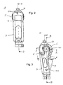
- the oscillating axis 6 is aligned parallel to the hinge axis 5 and arranged offset side and downwardly with respect to this.
- the joint upper part 2 is further articulated via a swing phase control element 7 to the lower joint part 3.
- the swing phase control element 7 is designed as a piston-cylinder system, in which a piston rod 8 can be pushed into a cylinder 9 and pulled out of this again.
- the articulation is effected via a rotatable attachment of the piston rod 8 of the swing phase control element 7 to the joint upper part 2 with a rotation axis 10 and a rotatable attachment of the cylinder 9 of the swing phase control element 7 to the hinge base 3 with a rotation axis eleventh
- the swing phase control element 7 is preferably formed as a pneumatic piston-cylinder device, which dampens the movement of the piston rod 8 relative to the cylinder 9 depending on the movement speed.
- a hydraulic piston-cylinder device or a similar device conceivable that dampens the movement of the piston rod 8 relative to the cylinder 9.
- Fig. 1a to 1c illustrated assembled state of the brake knee joint 1 in a prosthetic leg connects to the upper joint part 2 a thigh part 12 and to the lower joint part 3, a foot part 13 at.
- the joint is shown in a stretched state.
- a first power transmission element 14 and a second power transmission element 15 are arranged substantially coaxially to the hinge axis 5 in the interior of the brake knee joint.
- the first power transmission element 14 is rotatably arranged about the hinge axis 5 with respect to the hinge center part 4.
- the second power transmission element 15 is limited along the hinge axis 5 movable, but it is non-rotatably connected to the hinge center part 4 with respect to the hinge axis 5.
- the first power transmission element 14 is substantially cylindrical formed with a circular coaxial bore 14b.
- the first end face 14a is formed in a circular shape with a substantially flat surface.
- a coaxially encircling groove 14e is formed, which serves to guide first ball bearing balls 16.
- the second end face 14c has in the illustrated embodiment, three spindle-shaped rising around the coaxial bore 14b circumferential surfaces 14d.
- the spindle-shaped rise is such that in the circular counterclockwise rotation around the bore 14b on the second end face 14c, the distance to the first end face is getting larger until the end of the respective surface 14d is reached and the distance then in the form of a step to Beginning of the next area decreases again to the initial value.
- a groove 14f for guiding second ball bearing balls 17 is formed coaxially circumferentially in the surfaces 14d.
- first cam 14h which protrudes radially outwardly from the cylinder jacket substantially and which serves to introduce force, which will be described in detail later.
- recess 14i formed in a substantially tangential direction, which forms a second cam 14j which protrudes somewhat from the cylinder jacket and whose cam surface serves to engage a spring element for setting the release force.
- the second power transmission element 15 is also substantially cylindrical with a coaxial bore formed with a substantially square cross-section.
- a first end face 15a of the second force transmission element 15 is formed, like the cylinder jacket surface, with a flat surface.
- the second end face 15c has, in analogy to the second end face 14c of the first force transmission element 14, spindle-shaped rising surfaces 15d and a groove 15f.
- Fig. 9c shows a perspective view of the first and second power transmission element 14, 15 in the assembled state. Between the grooves 14f, 15f are in this state, the second ball bearing balls 17 which in Fig. 9c not shown, but in Fig. 6 are shown. As in the Fig. 9a to 9c can be seen, the first end faces 14a, 15a are aligned parallel to each other. It is in Fig. 9c it can be seen that the distance between the first end faces 14a, 15a increases when the second force transmission element 15 is held stationary and the first force transmission element 14 is rotated about the cylinder axis in a clockwise direction. Thus, the first and the second force transmission element 14, 15 form a lifting spindle.
- the joint middle part 4 is formed such that it forms two free legs 4a, between which the first 14 and the second power transmission element 15 are used in the assembled state. Air gaps 19 are left free between the first end faces 14a, 15a and the free legs 4a, 4a.
- holes 4b, 4b are provided, which are arranged coaxially to the hinge axis 5 and in a first portion 4c with a smaller cross-section each having a substantially square cross-section. In a second section 4d, these holes each have a larger circular cross-section.
- brake discs 20, 21 are provided.
- the brake disk 20 facing the first force transmission element 14 has a first section 20a with a smaller, essentially square cross-section perpendicular to the hinge axis 5 and a second section 20b with a larger, circular cross-section.
- the first portion 20 a is formed such that a movement in the axial direction of the hinge axis 5 in the bore 4 b is possible, but no rotation of the brake disc 20 about the hinge axis 5 with respect to the hinge center part 4.
- the radius of the second portion 20 b is slightly smaller than the radius of the second portion 4d of the bore 4b, so that it is partially retractable in this.
- the brake disk 20 On the side facing the first power transmission element 14, the brake disk 20 furthermore has a groove 20c extending coaxially with respect to the joint axis 5 for guiding the first ball bearing balls 16.
- the second power transmission element 15 facing brake disk 21 has, as from the Fig. 6 and 8th can also be seen, also a first portion 21a and a second portion 21b, which as the first 20a and the second portion 20b of the brake disc 20 are formed.
- the brake disk 21 furthermore has a third portion 21c which has a substantially square, smaller cross section than the second portion 21b.
- the cross section of the third portion 21 c is just chosen so that engagement in the substantially square hole 15 b of the second power transmission element 15 can take place and this is secured against rotation with respect to the brake disk 21.
- the cross section of the second portion 21b is selected analogous to the second portion 20b of the brake disc 20 so that engagement in the substantially square hole 4b of the joint center part 4 can be made such that a movement in the axial direction of the hinge axis 5 in the bore 4b is possible, but no rotation of the brake disc 20 about the hinge axis 5 with respect to the joint center part. 4
- Fig. 5 presses the second cam 14j of the first power transmission element 14 against the spring element 18, whose abutment is formed by a spring force adjustment screw 23 which is connected to the joint upper part 2 via a thread.
- the counterforce to the by the spring element 18 to the about the hinge axis 5 rotatably mounted first power transmission element 14 exerted force acting on the first cam 14h clearance compensation screw 24 which is connected via a thread with the upper hinge part 2.
- the structure described above makes it possible that the first power transmission element 14 via the first 16 and second ball bearing balls 17 mounted opposite to the joint center part 4 and held in this non-rotatably held second power transmission element 15 can be rotated.
- the Hubspindelhal the interaction of the first 14 and the second power transmission element 15 while the first end surfaces 14a, 15a and on this the two brake discs 20, 21 moves outwardly.
- the first 14 and the second power transmission element 15 and the brake discs 20, 21 are guided by the held in the lower joint part 3 hinge axis 5 in the joint center part 4.
- the outwardly moving brake discs 20, 21 press against the discs 22 secured in the joint bottom part 3 and thereby brake a movement of the joint center part 4 with respect to the joint bottom part 3 about the joint axis 5.
- the joint middle part 4 is rotated about the hinge axis 5 in a clockwise direction relative to the lower joint part 3.
- the swing axis 6 also moves clockwise around the Joint axis 5.
- the oscillating axis moves in Fig. 3 So on a circular path to the top left.
- the rotation axis 10 also moves on a circular path in a clockwise direction about the hinge axis 5.
- the rotation axis 10 moves in Fig. 3 So basically down.
- Fig. 5 described the activation of the braking device by foot load.
- the joint upper part 2 which is rotatable about the oscillation axis 6 to the joint middle part 4, pressed by the first cam 14h with the edge 2a against the stop 4a of the joint center part 4.
- the first 14 and the second power transmission element 15 are in this situation in a rest state in which the brake discs 20, 21 are not pressed outward and consequently the rotation of the joint center part 4 is not braked relative to the lower joint part 3 about the hinge axis 5.
- a vertical force component acts on the hinge top 2 from above such that the torque transmitted from the lash adjuster screw 24 to the first force transmission element 14 via the first cam 14 exceeds the torque transmitted by the spring element 18 via the second cam 14j
- the brake disks 20, 21 moves outwardly and a rotation of the joint center part 4 braked about the hinge axis 5 relative to the lower joint part 3.
- the plate spring 18 presses the first force transmission element 14 back again and the joint upper part 2 again into the stop 4a on the middle part 4 so that the brake is released again.
- the release force of the disc brake can be adjusted via the spring force adjustment screw 23 by the bias of the plate spring 18 by turning the Spring force adjustment screw 23 is either increased or decreased.
- a pre-twisting of the first power transmission element 14 relative to the second power transmission element 15 can be achieved, so that when a wear of the brake pads a simple readjustment can take place.
- the knee joint prosthesis described above due to the particular arrangement of the swing axle 6 in an array parallel, stretch side and offset on the side of the hinge base relative to the hinge axis 5 down the particular advantage that the braking effect of the disc brake is dependent on, in which phase of a step the prosthetic leg is.
- the oscillating axis 6 forms a large lever B to the hinge axis 5 when placing the heel of the leg prosthesis with respect to a force acting vertically from above, ie the braking effect with a relatively small acting body load of the leg prosthesis begins.
- the lever A which is formed when placing the toe, much smaller, so that a greater body load of the prosthetic leg is required for the braking effect, ie the brake releasing earlier releases.
- This effect especially in conjunction with the disc brake, allows a more natural movement of the leg while walking, since it avoids the brake still engaging in initiating the swing phase of the leg.
- a high stability of Leg prosthesis achieved in the stance phase.
- the execution of the knee joint prosthesis with the two power transmission elements 14, 15 also leads to the fact that the strength of the braking effect can be controlled by the dosage of the applied vertical force component by the prosthesis wearer, so that the properties of the knee joint prosthesis are significantly improved.
- the weight of the knee joint prosthesis can be kept low and thus the wearing comfort can be increased.
- the first power transmission element in the form of a wedge, which is driven by the action of the triggering force between two inclined planes and these are pressed to exert the force on a brake discs or to the outside.
- the wedge is then expelled again on discharge and consequently no more braking force exerted on the brake discs.
Landscapes
- Health & Medical Sciences (AREA)
- Transplantation (AREA)
- Heart & Thoracic Surgery (AREA)
- Oral & Maxillofacial Surgery (AREA)
- Engineering & Computer Science (AREA)
- Biomedical Technology (AREA)
- Cardiology (AREA)
- Vascular Medicine (AREA)
- Life Sciences & Earth Sciences (AREA)
- Animal Behavior & Ethology (AREA)
- General Health & Medical Sciences (AREA)
- Public Health (AREA)
- Veterinary Medicine (AREA)
- Orthopedic Medicine & Surgery (AREA)
- Prostheses (AREA)
Description
- Die Erfindung betrifft eine Kniegelenkprothese nach dem Oberbegriff des Patentanspruchs 1.
- Eine Kniegelenkprothese für eine Beinprothese ist zum Beispiel aus der OE 3241695 C2 bekannt. Die Kniegelenkprothese weist ein Gelenkoberteil und ein Gelenkunterteil auf, die über eine Gelenkachse miteinander verbunden sind. Zum Erzeugen einer Bremswirkung, die bei Belastung der Beinprothese mit dem Körpergewicht des Prothesenträgers ein Abknicken in dem Kniegelenk verhindert, sind zwei Bremsflächen vorgesehen, die mit einem Bremsbelag versehen sind und durch Verkippen gegeneinander bei Gewichtsbelastung eine Bremswirkung erzeugen. Eine solche Kniegelenkprothese ermöglicht jedoch keine genaue Ansteuerung der Bremseinrichtung durch die Größe der einwirkenden Körperkraft. Das Auslösen der Bremse ist zudem unabhängig davon, in welcher Phase eines Schrittes sich die Beinprothese befindet, d.h. die Stärke der Bremswirkung tritt unabhängig davon auf, ob z.B. die Spitze des Fußes der Beinprothese belastet wird oder die Ferse. Eine Unterstützung eines natürlichen Gangs kann somit nicht erfolgen.
- Ein weiterer Stand der Technik ist in
US-A-4 152 787 angegeben. - Es sind weiterhin Kniegelenkprothesen mit einer so genannten Wickelbremse bekannt, bei der bei Körperbelastung der Radius eines koaxial zu der Gelenkachse angeordneten geschlitzten Zylinders verjüngt wird, sodass die Innenseite dieses Zylinders auf die Gelenkachse einwirkt und so eine Bremswirkung erzeugt wird. Bei diesen Wickelbremsen tritt jedoch das Problem auf, dass die Bremse beim Entlasten die Beugebewegung nicht unmittelbar wieder freigibt, also ein selbsthemmender Effekt auftritt. Dieser Effekt führt dazu, dass sich die Prothesenträger eine unnatürliche Gangart aneignen, bei der beim Bewegen der Hüfte nach vorne im Laufe eines Schrittes diese immer zusätzlich angehoben wird, um die Wickelbremse wieder frei zu geben.
- Aufgabe der Erfindung ist es, eine verbesserte Kniegelenkprothese zu schaffen.
- Die Aufgabe wird gelöst durch eine Kniegelenkprothese nach Anspruch 1. Weiterbildungen der Erfindung sind in den Unteransprüchen gekennzeichnet.
- Die Kniegelenkprothese hat insbesondere den Vorteil, dass das Blockieren der Bremseinrichtung bei Entlastung sofort gelöst und zugleich eine belastungsabhängige zur eingeleiteten Gewichtskraft proportionale Bremskraft erzielt wird.
- Weitere Merkmale und Zweckmäßigkeiten der Erfindung ergeben
sich aus der Beschreibung von Ausführungsbeispielen anhand der beigefügten Zeichnungen. Von den Figuren zeigen: -
Fig. 1a bis 1c eine schematische Darstellung einer Beinprothese mit einem Kniegelenk einer Ausführungsform der vorliegenden Erfindung in drei verschiedenen Beinstellungen; -
Fig. 2 eine Vorderansicht eines Kniegelenks einer Ausführungsform der vorliegenden Erfindung in gestreckter Stellung; -
Fig. 3 eine Seitenansicht des inFig. 2 dargestellten Kniegelenks; -
Fig. 4 eine Rückansicht des inFig. 2 dargestellten Kniegelenks; -
Fig. 5 eine teilgeschnittene Seitenansicht des inFig. 2 dargestellten Kniegelenks; -
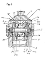
Fig. 6 einen Schnitt entlang der Linie B-B inFig. 3 durch einen oberen Teil des Kniegelenks; -
Fig. 7 einen Schnitt entlang der Linie c-c inFig. 3 durch einen oberen Teil des Kniegelenks; -
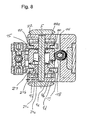
Fig. 8 einen Schnitt entlang der Linie A-A inFig. 3 durch einen oberen Teil des Kniegelenks; -
Fig. 9a eine Vorderansicht des ersten und des zweiten Kraftübertragungselements des Kniegelenks gemäß einer Ausführungsform der vorliegenden Erfindung; -
Fig. 9b eine perspektivische Darstellung des ersten und des zweiten Kraftübertragungselements; -
Fig. 9c eine perspektivische Darstellung des ersten und des zweiten Kraftübertragungselements im zusammengesetzten Zustand; - In den
Fig. 1a bis 1c ist ein Kniegelenk, im Weiteren auch als Bremskniegelenk bezeichnet, einer Ausführungsform der vorliegenden Erfindung in einer Beinprothese dargestellt. Wie in Fig. I zu erkennen ist, weist das Bremskniegelenk I ein Gelenkoberteil 2, ein Gelenkunterteil 3 und ein dazwischen angeordnetes Gelenkmittelteil 4 auf. Das Gelenkmittelteil 4 ist um eine Gelenkachse 5 drehbar mit dem Gelenkunterteil 3 verbunden. Das Gelenkoberteil 2 ist mit dem Gelenkmittelteil 4 um eine Schwingachse 6 schwenkbar verbunden. Die Schwingachse 6 ist parallel zu der Gelenkachse 5 ausgerichtet und streckseitig und nach unten versetzt bezüglich dieser angeordnet. - Wie insbesondere aus den
Fig. 2 bis 5 zu ersehen ist, ist das Gelenkoberteil 2 weiterhin über ein Schwungphasensteuerungselement 7 an das Gelenkunterteil 3 angelenkt. Das Schwungphasensteuerungselement 7 ist als ein Kolben-Zylinder-System ausgebildet, bei dem eine Kolbenstange 8 in einen Zylinder 9 hineingeschoben und wieder aus diesem herausgezogen werden kann. Die Anlenkung erfolgt über eine drehbare Befestigung der Kolbenstange 8 des Schwungphasensteuerungselements 7 an dem Gelenkoberteil 2 mit einer Drehachse 10 und eine drehbare Befestigung des Zylinders 9 des Schwungphasensteuerungselements 7 an dem Gelenkunterteil 3 mit einer Drehachse 11. - Das Schwungphasensteuerungselement 7 ist vorzugsweise als eine pneumatische Kolben-Zylinder-Einrichtung ausgebildet, die die Bewegung der Kolbenstange 8 relativ zu dem Zylinder 9 abhängig von der Bewegungsgeschwindigkeit dämpft. Alternativ ist auch die Verwendung einer hydraulischen Kolben-Zylinder-Einrichtung oder einer ähnlichen Vorrichtung denkbar, die die Bewegung der Kolbenstange 8 relativ zu dem Zylinder 9 dämpft.
- In dem in den
Fig. 1a bis 1c dargestellten montierten Zustand des Bremskniegelenks 1 in einer Beinprothese schließt an das Gelenkoberteil 2 ein Oberschenkelteil 12 und an das Gelenkunterteil 3 ein Fußteil 13 an. Das Gelenk ist jeweils in einem gestreckten Zustand dargestellt. - Anhand der
Figuren 5 bis 9b wird im Folgenden der Aufbau der Bremseinrichtung der Kniegelenkprothese beschrieben. Wie aus denFig. 5 und6 zu erkennen ist, sind im Wesentlichen koaxial zu der Gelenkachse 5 im Inneren des Bremskniegelenks ein erstes Kraftübertragungselement 14 und ein zweites Kraftübertragungselement 15 angeordnet. - Das erste Kraftübertragungselement 14 ist um die Gelenkachse 5 bezüglich des Gelenkmittelteils 4 drehbar angeordnet. Das zweite Kraftübertragungselement 15 ist begrenzt entlang der Gelenkachse 5 bewegbar, es ist jedoch drehfest bezüglich der Gelenkachse 5 mit dem Gelenkmittelteil 4 verbunden.
- Anhand der
Fig. 9a und 9b werden nun in Verbindung mitFig. 6 das erste Kraftübertragungselement 14 und das zweite Kraftübertragungselement 15 detailliert beschrieben. - Wie in den
Fig. 6 und9a bis 9c gezeigt ist, ist das erste Kraftübertragungselement 14 im Wesentlichen zylindrisch mit einer kreisförmigen koaxialen Bohrung 14b ausgebildet. Die erste Stirnfläche 14a ist kreisförmig mit einer im Wesentlichen ebenen Oberfläche ausgebildet. In der Stirnfläche 14a ist eine koaxial ringsumlaufende Rille 14e ausgebildet, die zur Führung erster Kugellagerkugeln 16 dient. Die zweite Stirnfläche 14c weist in der dargestellten Ausführungsform drei spindelförmig ansteigende um die koaxiale Bohrung 14b umlaufende Flächen 14d auf. Der spindelförmige Anstieg ist dabei derart, dass beim kreisförmigen Umlaufen entgegen dem Uhrzeigersinn um die Bohrung 14b auf der zweiten Stirnfläche 14c der Abstand zu der ersten Stirnfläche immer größer wird bis das Ende der jeweiligen Fläche 14d erreicht ist und der Abstand dann in Form einer Stufe zum Anfang der nächsten Fläche wieder auf den Ausgangswert abnimmt. Auf der zweiten Stirnfläche 14c ist koaxial umlaufend in den Flächen 14d eine Rille 14f zur Führung zweiter Kugellagerkugeln 17 ausgebildet. - Von dem Zylindermantel 14g ausgehend befindet sich auf einer Seite eine erste Nocke 14h, die im Wesentlichen von dem Zylindermantel radial nach außen ragt und der Krafteinbringung dient, die später noch ausführlich beschrieben wird. Auf der anderen Seite des Zylindermantels 14g befindet sich eine in im Wesentlichen tangentialer Richtung ausgebildete Ausnehmung 14i, die eine zweite Nocke 14j bildet, die etwas aus dem Zylindermantel ragt und deren Nockenfläche zum Angreifen eines Federelements zum Einstellen der Auslösekraft dient.
- Das zweite Kraftübertragungselement 15 ist ebenfalls im Wesentlichen zylindrisch mit einer koaxialen Bohrung mit im Wesentlichen quadratischem Querschnitt ausgebildet. Eine erste Stirnfläche 15a des zweiten Kraftübertragungselements 15 ist ebenso wie die Zylindermantelfläche mit einer ebenen Oberfläche ausgebildet. Die zweite Stirnfläche 15c weist analog zu der zweiten Stirnfläche 14c des ersten Kraftübertragungselements 14 spindelförmig ansteigende Flächen 15d und eine Rille 15f auf.
-
Fig. 9c zeigt eine perspektivische Darstellung des ersten und des zweiten Kraftübertragungselements 14, 15 im zusammengesetzten Zustand. Zwischen den Rillen 14f, 15f befinden sich in diesem Zustand die zweiten Kugellagerkugeln 17, die inFig. 9c nicht dargestellt sind, jedoch inFig. 6 gezeigt sind. Wie in denFig. 9a bis 9c zu erkennen ist, sind die ersten Stirnflächen 14a, 15a parallel zueinander ausgerichtet. Es ist inFig. 9c zu erkennen, dass der Abstand zwischen den ersten Stirnflächen 14a, 15a zunimmt, wenn das zweite Kraftübertragungselement 15 ortsfest gehalten wird und das erste Kraftübertragungselement 14 um die Zylinderachse im Uhrzeigersinn gedreht wird. Somit bilden das erste und das zweite Kraftübertragungselement 14, 15 eine Hubspindel. - Wie aus
Fig. 7 ersichtlich ist, ist das Gelenkmittelteil 4 derart ausgebildet, dass es zwei freie Schenkel 4a bildet, zwischen denen das erste 14 und das zweite Kraftübertragungselement 15 im zusammengebauten Zustand eingesetzt sind. Zwischen den ersten Stirnflächen 14a, 15a und den freien Schenkeln 4a, 4a sind dabei Luftspalte 19 freigelassen. - Wie insbesondere aus den
Fig. 6 und8 zu ersehen ist, sind in den freien Schenkeln 4a, 4a Bohrungen 4b, 4b vorgesehen, die koaxial zu der Gelenkachse 5 angeordnet sind und in einem ersten Abschnitt 4c mit kleinerem Querschnitt je einen im Wesentlichen quadratischen Querschnitt aufweisen. In einem zweiten Abschnitt 4d weisen diese Bohrungen je einen größeren kreisförmigen Querschnitt auf. Durch diese Bohrungen 4b, 4b hindurchgreifend sind koaxial zu der Gelenkachse 5 angeordnete Bremsscheiben 20, 21 vorgesehen. - Die dem ersten Kraftübertragungselement 14 zugewandte Bremsscheibe 20 weist einen ersten Abschnitt 20a mit einem kleineren, im Wesentlichen quadratischen Querschnitt senkrecht zur Gelenkachse 5 und einen zweiten Abschnitt 20b mit einem größeren, kreisförmigen Querschnitt auf. Der erste Abschnitt 20a ist derart ausgebildet, dass eine Bewegung in der axialen Richtung der Gelenkachse 5 in der Bohrung 4b möglich ist, jedoch keine Rotation der Bremsscheibe 20 um die Gelenkachse 5 bezüglich des Gelenkmittelteils 4. Der Radius des zweiten Abschnitts 20b ist etwas kleiner als der Radius des zweiten Abschnitts 4d der Bohrung 4b, sodass er teilweise in diesen versenkbar ist. Auf der dem ersten Kraftübertragungselement 14 zugewandten Seite weist die Bremsscheibe 20 weiterhin eine zu der Gelenkachse 5 koaxial verlaufende Rille 20c zum Führen der ersten Kugellagerkugeln 16 auf.
- Die dem zweiten Kraftübertragungselement 15 zugewandte Bremsscheibe 21 weist, wie aus den
Fig. 6 und8 zu erkennen ist, ebenfalls einen ersten Abschnitt 21a und einen zweiten Abschnitt 21b auf, die wie der erste 20a und der zweite Abschnitt 20b der Bremsscheibe 20 ausgebildet sind. Die Bremsscheibe 21 weist jedoch anschließend an den zweiten Abschnitt 21b auf der dem zweiten Kraftübertragungselement 15 zugewandten Seite weiterhin einen dritten Abschnitt 21c auf, der einen im Wesentlichen quadratischen, kleineren Querschnitt als der zweite Abschnitt 21b aufweist. Der Querschnitt des dritten Abschnitts 21c ist gerade so gewählt, dass ein Eingreifen in die im Wesentlichen quadratische Bohrung 15b des zweiten Kraftübertragungselements 15 erfolgen kann und dieses gegen Verdrehen gegenüber der Bremsscheibe 21 gesichert ist. Der Querschnitt des zweiten Abschnitts 21b ist analog zu dem zweiten Abschnitt 20b der Bremsscheibe 20 so gewählt, dass ein Eingreifen in die im Wesentlichen quadratische Bohrung 4b des Gelenkmittelteils 4 derart erfolgen kann, dass eine Bewegung in der axialen Richtung der Gelenkachse 5 in der Bohrung 4b möglich ist, jedoch keine Rotation der Bremsscheibe 20 um die Gelenkachse 5 bezüglich des Gelenkmittelteils 4. - Angrenzend an die den Kraftübertragungselementen 14, 15 abgewandten Seitenflächen der Bremsscheiben 20, 21 befinden sich in dem Gelenkunterteil befestigte bevorzugt als Stahlscheiben ausgebildete Scheiben 22 mit Bremsbelag.
- Wie in
Fig. 5 zu erkennen ist, drückt die zweite Nocke 14j des ersten Kraftübertragungselements 14 gegen das Federelement 18, dessen Gegenlager von einer Federkraft-Einstellschraube 23 gebildet wird, die mit dem Gelenkoberteil 2 über ein Gewinde verbunden ist. Die Gegenkraft zu der durch das Federelement 18 auf das um die Gelenkachse 5 drehbar gelagerte erste Kraftübertragungselement 14 ausgeübten Kraft bildet die auf die erste Nocke 14h einwirkende Spielausgleichsschraube 24, die über ein Gewinde mit dem Gelenkoberteil 2 verbunden ist. - Der zuvor beschriebene Aufbau ermöglicht es, dass das erste Kraftübertragungselement 14 über die ersten 16 und zweiten Kugellagerkugeln 17 gelagert gegenüber dem Gelenkmittelteil 4 und dem in diesem verdrehgesichert gehaltenen zweiten Kraftübertragungselement 15 verdreht werden kann. Durch das Hubspindelprinzip des Zusammenwirkens des ersten 14 und des zweiten Kraftübertragungselements 15 werden dabei die ersten Stirnflächen 14a, 15a und über diese die beiden Bremsscheiben 20, 21 nach außen bewegt. Das erste 14 und das zweite Kraftübertragungselement 15 sowie die Bremsscheiben 20, 21 werden dabei von der in dem Gelenkunterteil 3 gehaltenen Gelenkachse 5 in dem Gelenkmittelteil 4 geführt. Die nach außen bewegten Bremsscheiben 20, 21 pressen gegen die in dem Gelenkunterteil 3 befestigten Scheiben 22 und bremsen dadurch eine Bewegung des Gelenkmittelteils 4 gegenüber dem Gelenkunterteil 3 um die Gelenkachse 5.
- Anhand von
Fig. 3 wird nun zuerst ein Beugen des Bremskniegelenks 1 ohne ein Auslösen der Bremseinrichtung beschrieben. - Beim langsamen Beugen des Bremskniegelenks mit geringer Krafteinwirkung wird das Gelenkmittelteil 4 um die Gelenkachse 5 im Uhrzeigersinn gegenüber dem Gelenkunterteil 3 verdreht. Bei dieser Drehbewegung bewegt sich die Schwingachse 6 ebenfalls im Uhrzeigersinn um die Gelenkachse 5. Die Schwingachse bewegt sich in
Fig. 3 also auf einer Kreisbahn nach links oben. Bei geringer Krafteinwirkung bewegt sich das an der Schwingachse 6 an das Gelenkmittelteil 4 angekoppelte Gelenkoberteil 2 ebenfalls im Uhrzeigersinn mit dem Gelenkmittelteil 4 mit, sodass sich die Drehachse 10 ebenfalls auf einer kreisförmigen Bahn im Uhrzeigersinn um die Gelenkachse 5 bewegt. Die Drehachse 10 bewegt sich inFig. 3 also im Wesentlichen nach unten. - Bei Bewegung der Drehachse 10 nach unten wird die Kolbenstange 8 in den Zylinder 9 hineingeschoben und es findet eine leichte Drehbewegung des Schwungphasensteuerungselements 7 um die Drehachsen 10 und 11 relativ zu dem Gelenkoberteil 2 bzw. dem Gelenkunterteil 13 statt.
- Bei einer Streckung des Bremskniegelenks findet die zuvor beschriebene Bewegung in umgekehrter Richtung statt.
- Im Folgenden wird Bezug nehmend auf
Fig. 5 die Ansteuerung der Bremseinrichtung durch Fußbelastung beschrieben. - Mit der Federkraft-EinsteIlschraube 23 ist über das Federelement 18 eine vorbestimmte Auslösekraft eingestellt. Diese wird abhängig von dem Gewicht und der Aktivität des Prothesenträgers eingestellt.
- Wenn keine vertikale Kraft von oben auf das Gelenkoberteil 2 wirkt und das Federelement 18 eine Vorspannung aufweist, dann wird das Gelenkoberteil 2, das um die Schwingachse 6 zu dem Gelenkmittelteil 4 drehbar ist, durch die erste Nocke 14h mit der Kante 2a gegen den Anschlag 4a des Gelenkmittelteils 4 gedrückt. Das erste 14 und das zweite Kraftübertragungselement 15 befinden sich in dieser Situation in einem Ruhezustand, in dem die Bremsscheiben 20, 21 nicht nach außen gedrückt werden und folglich die Rotation des Gelenkmittelteils 4 relativ zu dem Gelenkunterteil 3 um die Gelenkachse 5 nicht gebremst wird.
- Wirkt eine vertikale Kraftkomponente von oben derart auf das Gelenkoberteil 2 ein, dass das von der Spielausgleichsschraube 24 über die erste Nocke 14h auf das erste Kraftübertragungselement 14 übertragene Drehmoment das Drehmoment überwiegt, das von dem Federelement 18 über die zweite Nocke 14j übertragen wird, so verkippt das Gelenkoberteil 2 gegenüber dem Gelenkmittelteil 4 um die Schwingachse 6. Bei dem Verkippen wird das erste Kraftübertragungselement 14 gegenüber dem zweiten Kraftübertragungselement 15 um die Gelenkachse 5 verdreht und folglich werden wie bereits oben beschrieben die Bremsscheiben 20, 21 nach außen bewegt und eine Drehung des Gelenkmittelteils 4 um die Gelenkachse 5 relativ zu dem Gelenkunterteil 3 gebremst.
- Wird die vertikale Kraftkomponente wieder aufgehoben, so drückt die Tellerfeder 18 das erste Kraftübertragungselement 14 wieder zurück und das Gelenkoberteil 2 somit wieder in den Anschlag 4a am Gelenkmittelteil 4, sodass die Bremse wieder freigegeben wird.
- Die Auslösekraft der Scheibenbremse kann über die Federkraft- Einstellschraube 23 justiert werden, indem die Vorspannung der Tellerfeder 18 durch Verdrehen der Federkraft-Einstellschraube 23 entweder erhöht oder verringert wird.
- Über die Spielausgleichsschraube 24 kann ein Vorverdrehen des ersten Kraftübertragungselements 14 gegenüber dem zweiten Kraftübertragungselement 15 erreicht werden, sodass bei einem auftretenden Verschleiß der Bremsbeläge eine einfache Nachjustierung erfolgen kann.
- Wie anhand der
Fig. 1a bis 1c zu sehen ist, weist die zuvor beschriebene Kniegelenkprothese aufgrund der besonderen Anordnung der Schwingachse 6 in einer Anordnung parallel, streckseitig und auf der Seite des Gelenkunterteils bezüglich der Gelenkachse 5 nach unten versetzt den besonderen Vorteil auf, dass die Bremswirkung der Scheibenbremse abhängig davon ist, in welcher Phase eines Schrittes sich die Beinprothese befindet. - In der
Fig. 1a ist zu erkennen, dass die Schwingachse 6 beim Aufsetzen der Ferse der Beinprothese bezüglich einer vertikal von oben angreifenden Kraft einen großen Hebel B zu der Gelenkachse 5 bildet, d.h. die Bremswirkung bei einer relativ geringen einwirkenden Körperbelastung der Beinprothese einsetzt. Wie in derFig. 1c gezeigt ist, ist der Hebel A, der beim Aufsetzen der Fußspitze gebildet ist, wesentlich kleiner, sodass für die Bremswirkung eine größere Körperbelastung der Beinprothese erforderlich ist, d.h. die Bremse beim Entlasten früher freigibt. Dieser Effekt ermöglicht besonders in Verbindung mit der Scheibenbremse eine natürlichere Bewegung des Beins beim Gehen, da Vermieden wird, dass die Bremse beim Einleiten der Schwungphase des Beines noch greift. Zugleich wird eine hohe Stabilität der Beinprothese in der Standphase erreicht. - Das Verwenden der Scheibenbremse führt zu einer deutlichen Reduktion der Abnutzung der Bremseinrichtung, sodass der Abstand erforderlicher Wartungsintervalle reduziert werden kann und die Zuverlässigkeit der Kniegelenkprothese deutlich verbessert ist.
- Die Ausführung der Kniegelenkprothese mit den beiden Kraftübertragungselementen 14, 15 führt außerdem dazu, dass die Stärke der Bremswirkung durch die Dosierung der einwirkenden vertikalen Kraftkomponente durch den Prothesenträger gesteuert werden kann, sodass die Eigenschaften der Kniegelenkprothese deutlich verbessert sind. Bei der Verwendung in Kombination mit einem pneumatisch arbeitenden Schwungphasensteuerungselement 7 kann weiterhin das Gewicht der Kniegelenkprothese niedrig gehalten und folglich der Tragekomfort erhöht werden.
- Es ist ebenfalls denkbar, z.B. das erste Kraftübertragungselement in Form eines Keils auszubilden, der bei Einwirken der auslösenden Kraft zwischen zwei schiefe Ebenen getrieben wird und diese dabei zum Ausüben der Kraft auf eine oder Bremsscheiben nach außen gedrückt werden. Bei einer solchen Vorrichtung wird der Keil dann bei Entlastung wieder ausgetrieben und folglich keine Bremskraft mehr auf die Bremsscheiben ausgeübt.
- Ebenso ist es denkbar, die Kraftübertragung über ein Winkelhebelsystem zu realisieren. Auch ist es denkbar, die Kraftübertragung über eine hydraulische Vorrichtung zu realisieren, bei der die auslösende Kraft auf einen Kolben wirkt und diese auf einen zweiten Kolben übertragen wird, der dann die übertragene Kraft auf die Bremsscheibe ausübt.
Claims (13)
- Bremskniegelenk für eine Beinprothese mit einem Gelenkoberteil (2), einem um eine Gelenkachse (5) relativ zu dem Gelenkoberteil (2) drehbaren Gelenkunterteil (3), und einer Bremseinrichtung (14, 15, 20, 21), die ein koaxial zur Gelenkachse (5) angeordnetes erstes Kraftübertragungselement (14) aufweist, auf das eine die Bremswirkung auslösende Kraft wirkt, und das die Kraft unter einem vorgegebenen Übertragungsverhältnis auf ein koaxial zur Gelenkachse (5) angeordnetes zweites Kraftübertragungselement (15) umsetzt, das die umgesetzte Kraft in bezüglich der Gelenkachse (5) im wesentlichen paralleler Richtung auf eine Bremsscheibe (20, 21) ausübt,
dadurch gekennzeichnet, dass
das erste Kraftübertragungselement (14) und das zweite Kraftübertragungselement (15) einander zugewandte Stirnflächen (14c, 15c) aufweisen, die jeweils spindelförmig ansteigende, umlaufende Flächen (14d, 15d) aufweisen. - Bremskniegelenk nach Anspruch 1, bei dem das erste und das zweite Kraftübertragungselement (14, 15) eine schiefe Ebene zur Umsetzung der Kraft ausbilden.
- Bremskniegelenk nach einem der Ansprüche 1 bis 2, mit einem zwischen dem Gelenkoberteil (2) und dem Gelenkunterteil (3) vorgesehenen Gelenkmittelteil (4), wobei das Gelenkmittelteil (4) mit entweder dem Gelenkoberteil (2) oder dem Gelenkunterteil (3) über die Gelenkachse (5) verbunden ist und mit dem jeweils anderen über eine Schwingachse (6) verbunden ist.
- Bremskniegelenk nach Anspruch 3, bei dem die Schwingachse (6) bezüglich der Gelenkachse (5) parallel, streckseitig und auf der Seite des Gelenkunterteils (3) angeordnet ist.
- Bremskniegelenk nach einem der Ansprüche 1 bis 4, bei dem das erste und das zweite Kraftübertragungselement (14, 15) derart ausgebildet sind, dass das erste Kraftübertragungselement (14) durch die die Bremswirkung auslösende Kraft um eine zu der Gelenkachse (5) im Wesentlichen parallele Rotationsachse gedreht wird und die umgesetzte Kraft das zweite Kraftübertragungselement (15) in im Wesentlichen zu der Gelenkachse (5) parallele Translation versetzt.
- Bremskniegelenk nach einem der Ansprüche 1 bis 5, bei dem das erste Kraftübertragungselement (14) und das zweite Kraftübertragungselement (15) eine auf der Gelenkachse (5) angeordnete Hubspindel bilden.
- Bremskniegelenk nach einem der Ansprüche 1 bis 4, bei dem die Kraftübertragung über ein hydraulisches System erfolgt.
- Bremskniegelenk nach einem der Ansprüche 1 bis 4, bei dem die Kraftübertragung über einen Winkelhebel erfolgt.
- Bremskniegelenk nach einem der Ansprüche 1 bis 8, bei dem in Richtung der Gelenkachse (5) auf beiden Seiten des zweiten Kraftübertragungselements (15) Bremsscheiben (20, 21) vorgesehen sind.
- Bremskniegelenk nach einem der Ansprüche 1 bis 9, bei dem die Voreinstellung der die Bremswirkung auslösenden Kraft durch eine vorgespannte Feder (18) erreicht wird.
- Bremskniegelenk nach einem der Ansprüche 1 bis 10, bei dem zur Dämpfung bei der Gehbewegung eine Kolben-Zylinder-Einrichtung (7) vorgesehen ist.
- Bremskniegelenk nach einem der Ansprüche 1 bis 11, bei dem die Bremseinrichtung (14, 15, 20, 21) durch Fußbelastung ansteuerbar ist.
- Bremskniegelenk nach einem der Ansprüche 1 bis 12, bei dem die auf das erste Kraftübertragungselement (14) einwirkende Kraft im Wesentlichen senkrecht bezüglich der Gelenkachse einwirkt.
Applications Claiming Priority (2)
| Application Number | Priority Date | Filing Date | Title |
|---|---|---|---|
| DE102004021250A DE102004021250B4 (de) | 2004-04-30 | 2004-04-30 | Kniegelenkprothese |
| PCT/DE2005/000764 WO2005104999A1 (de) | 2004-04-30 | 2005-04-26 | Kniegelenkprothese |
Publications (2)
| Publication Number | Publication Date |
|---|---|
| EP1742599A1 EP1742599A1 (de) | 2007-01-17 |
| EP1742599B1 true EP1742599B1 (de) | 2011-06-15 |
Family
ID=34972118
Family Applications (1)
| Application Number | Title | Priority Date | Filing Date |
|---|---|---|---|
| EP05749613A Expired - Lifetime EP1742599B1 (de) | 2004-04-30 | 2005-04-26 | Kniegelenkprothese |
Country Status (5)
| Country | Link |
|---|---|
| US (1) | US20090171470A1 (de) |
| EP (1) | EP1742599B1 (de) |
| AT (1) | ATE512646T1 (de) |
| DE (1) | DE102004021250B4 (de) |
| WO (1) | WO2005104999A1 (de) |
Families Citing this family (6)
| Publication number | Priority date | Publication date | Assignee | Title |
|---|---|---|---|---|
| DE102008059907A1 (de) * | 2008-12-02 | 2010-06-10 | Otto Bock Healthcare Gmbh | Orthopädietechnisches Gelenk |
| DE102011002117A1 (de) * | 2011-04-15 | 2012-10-18 | Horst Lautenschläger | Möbelscharnier |
| RU2505272C1 (ru) * | 2012-07-10 | 2014-01-27 | Открытое акционерное общество "Ракетно-космическая корпорация "Энергия" имени С.П. Королева" | Механизм коленного шарнира |
| WO2014124286A1 (en) * | 2013-02-07 | 2014-08-14 | Ossur Hf | Knee rotational adapter |
| WO2015126849A1 (en) * | 2014-02-18 | 2015-08-27 | össur hf | Prosthetic joint with cam locking mechanism |
| DE102017213300B3 (de) * | 2017-08-01 | 2019-01-24 | Bauerfeind Ag | Orthesengelenkschiene mit aktiv bewegter Pelotte und Gelenkorthese |
Family Cites Families (18)
| Publication number | Priority date | Publication date | Assignee | Title |
|---|---|---|---|---|
| US2024673A (en) * | 1932-12-02 | 1935-12-17 | Desoutter Brothers Ltd | Joint for artificial limbs |
| US2533008A (en) * | 1947-11-05 | 1950-12-05 | Gust Johnson | Artificial leg |
| US2863684A (en) * | 1956-10-05 | 1958-12-09 | Howard M Carroll | Artificial limb ankle joint assembly |
| GB1091015A (en) * | 1963-06-21 | 1967-11-15 | J E Hanger & Company Ltd | Improvements in joints for artificial limbs |
| US3871779A (en) * | 1963-09-26 | 1975-03-18 | James W Butler | Mechanical connections |
| GB1534181A (en) * | 1976-09-13 | 1978-11-29 | Blatchford & Sons Ltd C | Artificial leg with knee joint |
| US4064569A (en) * | 1976-09-23 | 1977-12-27 | Campbell Harry E | Artificial polycentric knee joint |
| US4135254A (en) * | 1977-06-13 | 1979-01-23 | Hosmer/Dorrance Corporation | Prosthetic knee apparatus |
| US4152787A (en) * | 1977-07-11 | 1979-05-08 | Joseph Meggyesy | Prosthetic knee joint having weight responsive brake |
| DE2841999C2 (de) * | 1978-09-27 | 1981-11-26 | Otto Bock, Orthopädische Industrie KG, 3428 Duderstadt | Künstliches Kniegelenk |
| DE3241695C2 (de) * | 1982-11-11 | 1985-09-05 | Heintz, Bruno, 7530 Pforzheim | Kniegelenk für eine Oberschenkelprothese |
| DE3909672A1 (de) * | 1988-03-25 | 1989-10-19 | Kobe Steel Ltd | Oberschenkelprothese |
| GB2244006B (en) * | 1990-05-04 | 1994-05-25 | Blatchford & Sons Ltd | An artificial limb |
| JPH0767899A (ja) * | 1993-09-06 | 1995-03-14 | Nabco Ltd | 義足用荷重ブレーキ |
| DE19511890C1 (de) * | 1995-03-31 | 1996-11-07 | Bock Orthopaed Ind | Prothesenbremsgelenk |
| GB9606219D0 (en) * | 1995-09-22 | 1996-05-29 | Blatchford & Sons Ltd | Knee prosthesis |
| WO2001045596A1 (de) * | 1999-12-21 | 2001-06-28 | Heggemann Gmbh | Mehrachsiges gelenk, insbesondere künstliches kniegelenk |
| TW549074U (en) * | 2001-06-06 | 2003-08-21 | Lin Prosthetic & Orthopaedic I | Artificial knee joint |
-
2004
- 2004-04-30 DE DE102004021250A patent/DE102004021250B4/de not_active Expired - Fee Related
-
2005
- 2005-04-26 EP EP05749613A patent/EP1742599B1/de not_active Expired - Lifetime
- 2005-04-26 AT AT05749613T patent/ATE512646T1/de active
- 2005-04-26 WO PCT/DE2005/000764 patent/WO2005104999A1/de not_active Ceased
- 2005-04-26 US US11/661,845 patent/US20090171470A1/en not_active Abandoned
Also Published As
| Publication number | Publication date |
|---|---|
| DE102004021250A1 (de) | 2005-11-24 |
| WO2005104999A1 (de) | 2005-11-10 |
| US20090171470A1 (en) | 2009-07-02 |
| DE102004021250B4 (de) | 2007-01-04 |
| ATE512646T1 (de) | 2011-07-15 |
| EP1742599A1 (de) | 2007-01-17 |
Similar Documents
| Publication | Publication Date | Title |
|---|---|---|
| EP0439028B1 (de) | Schwenkverbindung zwischen zwei Teilen eines orthopädie-technischen Hilfsmittels | |
| DE3716202C2 (de) | Scheibenbremse für Fahrzeuge | |
| EP0010177B1 (de) | Künstliches Kniegelenk | |
| DE60026564T2 (de) | Nachstellstrebe | |
| EP3084254A2 (de) | Anschlaganordnung und bremseinrichtung mit einer solchen | |
| EP1761218B1 (de) | Prothesengelenk | |
| DE2031511B2 (de) | Mechanische betaetigungsvorrichtung fuer fahrzeuginnenbackenbremsen | |
| EP2729224A1 (de) | Bremsvorrichtung für rollschuhe, rollbretter od. dgl. | |
| DE2740804C2 (de) | Beinprothesen-Kniegelenk | |
| DE2221105A1 (de) | Sicherheits-Skibindung | |
| DE102004021250B4 (de) | Kniegelenkprothese | |
| AT515189B1 (de) | Ferseneinheit für eine Tourenbindung und Tourenbindung | |
| CH638997A5 (de) | Sicherheitsskibindung mit einem um eine querachse schwenkbaren gehaeuse. | |
| DE69000206T2 (de) | Sicherheitsskibindung. | |
| EP1280482B1 (de) | Mehrachsiges künstliches kniegelenk | |
| DE1578850B2 (de) | Absatzhaltevorrichtung für Sicherheits-Skibindungen | |
| DE2802775C2 (de) | Sicherheitsskibindung mit einem um eine Querachse schwenkbaren Gehäuse | |
| DE102020120498B4 (de) | Prothesenfuß | |
| DE2429610C3 (de) | Sicherheitsskibindung | |
| DE69416272T2 (de) | Bremsvorrichtung für Rollschuhe | |
| DE102013004544B4 (de) | Prothesenkniegelenk mit Kniegelenksperre | |
| DE3321319C2 (de) | ||
| DE4202635A1 (de) | Bremszange fuer schreibenbremsen von schienenfahrzeugen | |
| DE102014013868B4 (de) | Betätigungseinrichtung für eine Innenbackenbremse mit selbsttätiger Nachstelleinrichtung | |
| DE2653677A1 (de) | Innenbacken-trommelbremse, insbesondere fuer kraftfahrzeuge |
Legal Events
| Date | Code | Title | Description |
|---|---|---|---|
| PUAI | Public reference made under article 153(3) epc to a published international application that has entered the european phase |
Free format text: ORIGINAL CODE: 0009012 |
|
| 17P | Request for examination filed |
Effective date: 20061115 |
|
| AK | Designated contracting states |
Kind code of ref document: A1 Designated state(s): AT BE BG CH CY CZ DE DK EE ES FI FR GB GR HU IE IS IT LI LT LU MC NL PL PT RO SE SI SK TR |
|
| DAX | Request for extension of the european patent (deleted) | ||
| 17Q | First examination report despatched |
Effective date: 20091001 |
|
| RAP1 | Party data changed (applicant data changed or rights of an application transferred) |
Owner name: MEDI GMBH & CO. KG |
|
| RAP1 | Party data changed (applicant data changed or rights of an application transferred) |
Owner name: TEKO AUTOMATION, MENSCH UND TECHNIK GMBH |
|
| GRAP | Despatch of communication of intention to grant a patent |
Free format text: ORIGINAL CODE: EPIDOSNIGR1 |
|
| GRAS | Grant fee paid |
Free format text: ORIGINAL CODE: EPIDOSNIGR3 |
|
| GRAA | (expected) grant |
Free format text: ORIGINAL CODE: 0009210 |
|
| AK | Designated contracting states |
Kind code of ref document: B1 Designated state(s): AT BE BG CH CY CZ DE DK EE ES FI FR GB GR HU IE IS IT LI LT LU MC NL PL PT RO SE SI SK TR |
|
| REG | Reference to a national code |
Ref country code: CH Ref legal event code: EP Ref country code: GB Ref legal event code: FG4D Free format text: NOT ENGLISH |
|
| REG | Reference to a national code |
Ref country code: IE Ref legal event code: FG4D Free format text: LANGUAGE OF EP DOCUMENT: GERMAN |
|
| REG | Reference to a national code |
Ref country code: DE Ref legal event code: R096 Ref document number: 502005011506 Country of ref document: DE Effective date: 20110728 |
|
| REG | Reference to a national code |
Ref country code: NL Ref legal event code: VDEP Effective date: 20110615 |
|
| PG25 | Lapsed in a contracting state [announced via postgrant information from national office to epo] |
Ref country code: LT Free format text: LAPSE BECAUSE OF FAILURE TO SUBMIT A TRANSLATION OF THE DESCRIPTION OR TO PAY THE FEE WITHIN THE PRESCRIBED TIME-LIMIT Effective date: 20110615 Ref country code: SE Free format text: LAPSE BECAUSE OF FAILURE TO SUBMIT A TRANSLATION OF THE DESCRIPTION OR TO PAY THE FEE WITHIN THE PRESCRIBED TIME-LIMIT Effective date: 20110615 |
|
| PG25 | Lapsed in a contracting state [announced via postgrant information from national office to epo] |
Ref country code: GR Free format text: LAPSE BECAUSE OF FAILURE TO SUBMIT A TRANSLATION OF THE DESCRIPTION OR TO PAY THE FEE WITHIN THE PRESCRIBED TIME-LIMIT Effective date: 20110916 Ref country code: CY Free format text: LAPSE BECAUSE OF FAILURE TO SUBMIT A TRANSLATION OF THE DESCRIPTION OR TO PAY THE FEE WITHIN THE PRESCRIBED TIME-LIMIT Effective date: 20110615 Ref country code: FI Free format text: LAPSE BECAUSE OF FAILURE TO SUBMIT A TRANSLATION OF THE DESCRIPTION OR TO PAY THE FEE WITHIN THE PRESCRIBED TIME-LIMIT Effective date: 20110615 Ref country code: SI Free format text: LAPSE BECAUSE OF FAILURE TO SUBMIT A TRANSLATION OF THE DESCRIPTION OR TO PAY THE FEE WITHIN THE PRESCRIBED TIME-LIMIT Effective date: 20110615 |
|
| PG25 | Lapsed in a contracting state [announced via postgrant information from national office to epo] |
Ref country code: NL Free format text: LAPSE BECAUSE OF FAILURE TO SUBMIT A TRANSLATION OF THE DESCRIPTION OR TO PAY THE FEE WITHIN THE PRESCRIBED TIME-LIMIT Effective date: 20110615 |
|
| REG | Reference to a national code |
Ref country code: IE Ref legal event code: FD4D |
|
| PG25 | Lapsed in a contracting state [announced via postgrant information from national office to epo] |
Ref country code: PT Free format text: LAPSE BECAUSE OF FAILURE TO SUBMIT A TRANSLATION OF THE DESCRIPTION OR TO PAY THE FEE WITHIN THE PRESCRIBED TIME-LIMIT Effective date: 20111017 Ref country code: IE Free format text: LAPSE BECAUSE OF FAILURE TO SUBMIT A TRANSLATION OF THE DESCRIPTION OR TO PAY THE FEE WITHIN THE PRESCRIBED TIME-LIMIT Effective date: 20110615 Ref country code: IS Free format text: LAPSE BECAUSE OF FAILURE TO SUBMIT A TRANSLATION OF THE DESCRIPTION OR TO PAY THE FEE WITHIN THE PRESCRIBED TIME-LIMIT Effective date: 20111015 Ref country code: EE Free format text: LAPSE BECAUSE OF FAILURE TO SUBMIT A TRANSLATION OF THE DESCRIPTION OR TO PAY THE FEE WITHIN THE PRESCRIBED TIME-LIMIT Effective date: 20110615 Ref country code: CZ Free format text: LAPSE BECAUSE OF FAILURE TO SUBMIT A TRANSLATION OF THE DESCRIPTION OR TO PAY THE FEE WITHIN THE PRESCRIBED TIME-LIMIT Effective date: 20110615 |
|
| PG25 | Lapsed in a contracting state [announced via postgrant information from national office to epo] |
Ref country code: PL Free format text: LAPSE BECAUSE OF FAILURE TO SUBMIT A TRANSLATION OF THE DESCRIPTION OR TO PAY THE FEE WITHIN THE PRESCRIBED TIME-LIMIT Effective date: 20110615 Ref country code: RO Free format text: LAPSE BECAUSE OF FAILURE TO SUBMIT A TRANSLATION OF THE DESCRIPTION OR TO PAY THE FEE WITHIN THE PRESCRIBED TIME-LIMIT Effective date: 20110615 Ref country code: SK Free format text: LAPSE BECAUSE OF FAILURE TO SUBMIT A TRANSLATION OF THE DESCRIPTION OR TO PAY THE FEE WITHIN THE PRESCRIBED TIME-LIMIT Effective date: 20110615 |
|
| RAP2 | Party data changed (patent owner data changed or rights of a patent transferred) |
Owner name: BIEDERMANN TECHNOLOGIES GMBH & CO. KG |
|
| PLBE | No opposition filed within time limit |
Free format text: ORIGINAL CODE: 0009261 |
|
| STAA | Information on the status of an ep patent application or granted ep patent |
Free format text: STATUS: NO OPPOSITION FILED WITHIN TIME LIMIT |
|
| REG | Reference to a national code |
Ref country code: DE Ref legal event code: R082 Ref document number: 502005011506 Country of ref document: DE Representative=s name: PRUEFER & PARTNER GBR, DE |
|
| 26N | No opposition filed |
Effective date: 20120316 |
|
| PG25 | Lapsed in a contracting state [announced via postgrant information from national office to epo] |
Ref country code: IT Free format text: LAPSE BECAUSE OF FAILURE TO SUBMIT A TRANSLATION OF THE DESCRIPTION OR TO PAY THE FEE WITHIN THE PRESCRIBED TIME-LIMIT Effective date: 20110615 |
|
| REG | Reference to a national code |
Ref country code: GB Ref legal event code: 732E Free format text: REGISTERED BETWEEN 20120531 AND 20120606 |
|
| REG | Reference to a national code |
Ref country code: DE Ref legal event code: R082 Ref document number: 502005011506 Country of ref document: DE Representative=s name: PRUEFER & PARTNER GBR, DE Effective date: 20120509 Ref country code: DE Ref legal event code: R081 Ref document number: 502005011506 Country of ref document: DE Owner name: BIEDERMANN TECHNOLOGIES GMBH & CO. KG, DE Free format text: FORMER OWNER: MEDI BAYREUTH WEIHERMUELLER & VOIGTMANN GMBH & CO. KG, 95448 BAYREUTH, DE Effective date: 20110603 Ref country code: DE Ref legal event code: R081 Ref document number: 502005011506 Country of ref document: DE Owner name: BIEDERMANN TECHNOLOGIES GMBH & CO. KG, DE Free format text: FORMER OWNER: TEKO AUTOMATION, MENSCH UND TECHNIK GMBH, 78054 VILLINGEN-SCHWENNINGEN, DE Effective date: 20120509 Ref country code: DE Ref legal event code: R082 Ref document number: 502005011506 Country of ref document: DE Representative=s name: PRUEFER & PARTNER MBB PATENTANWAELTE RECHTSANW, DE Effective date: 20120509 |
|
| PG25 | Lapsed in a contracting state [announced via postgrant information from national office to epo] |
Ref country code: DK Free format text: LAPSE BECAUSE OF FAILURE TO SUBMIT A TRANSLATION OF THE DESCRIPTION OR TO PAY THE FEE WITHIN THE PRESCRIBED TIME-LIMIT Effective date: 20110615 |
|
| REG | Reference to a national code |
Ref country code: DE Ref legal event code: R097 Ref document number: 502005011506 Country of ref document: DE Effective date: 20120316 |
|
| BERE | Be: lapsed |
Owner name: TEKO AUTOMATION, MENSCH UND TECHNIK G.M.B.H. Effective date: 20120430 |
|
| PG25 | Lapsed in a contracting state [announced via postgrant information from national office to epo] |
Ref country code: MC Free format text: LAPSE BECAUSE OF NON-PAYMENT OF DUE FEES Effective date: 20120430 |
|
| REG | Reference to a national code |
Ref country code: CH Ref legal event code: PL |
|
| PG25 | Lapsed in a contracting state [announced via postgrant information from national office to epo] |
Ref country code: LI Free format text: LAPSE BECAUSE OF NON-PAYMENT OF DUE FEES Effective date: 20120430 Ref country code: CH Free format text: LAPSE BECAUSE OF NON-PAYMENT OF DUE FEES Effective date: 20120430 Ref country code: BE Free format text: LAPSE BECAUSE OF NON-PAYMENT OF DUE FEES Effective date: 20120430 |
|
| PG25 | Lapsed in a contracting state [announced via postgrant information from national office to epo] |
Ref country code: ES Free format text: LAPSE BECAUSE OF FAILURE TO SUBMIT A TRANSLATION OF THE DESCRIPTION OR TO PAY THE FEE WITHIN THE PRESCRIBED TIME-LIMIT Effective date: 20110926 |
|
| PG25 | Lapsed in a contracting state [announced via postgrant information from national office to epo] |
Ref country code: BG Free format text: LAPSE BECAUSE OF FAILURE TO SUBMIT A TRANSLATION OF THE DESCRIPTION OR TO PAY THE FEE WITHIN THE PRESCRIBED TIME-LIMIT Effective date: 20110915 |
|
| REG | Reference to a national code |
Ref country code: AT Ref legal event code: PC Ref document number: 512646 Country of ref document: AT Kind code of ref document: T Owner name: BIEDERMANN TECHNOLOGIES GMBH & CO. KG, DE Effective date: 20130920 |
|
| PG25 | Lapsed in a contracting state [announced via postgrant information from national office to epo] |
Ref country code: TR Free format text: LAPSE BECAUSE OF FAILURE TO SUBMIT A TRANSLATION OF THE DESCRIPTION OR TO PAY THE FEE WITHIN THE PRESCRIBED TIME-LIMIT Effective date: 20110615 |
|
| PG25 | Lapsed in a contracting state [announced via postgrant information from national office to epo] |
Ref country code: LU Free format text: LAPSE BECAUSE OF NON-PAYMENT OF DUE FEES Effective date: 20120426 |
|
| PG25 | Lapsed in a contracting state [announced via postgrant information from national office to epo] |
Ref country code: HU Free format text: LAPSE BECAUSE OF FAILURE TO SUBMIT A TRANSLATION OF THE DESCRIPTION OR TO PAY THE FEE WITHIN THE PRESCRIBED TIME-LIMIT Effective date: 20050426 |
|
| REG | Reference to a national code |
Ref country code: FR Ref legal event code: PLFP Year of fee payment: 12 |
|
| REG | Reference to a national code |
Ref country code: FR Ref legal event code: PLFP Year of fee payment: 13 |
|
| PGFP | Annual fee paid to national office [announced via postgrant information from national office to epo] |
Ref country code: FR Payment date: 20170621 Year of fee payment: 13 |
|
| PGFP | Annual fee paid to national office [announced via postgrant information from national office to epo] |
Ref country code: AT Payment date: 20170424 Year of fee payment: 13 |
|
| REG | Reference to a national code |
Ref country code: AT Ref legal event code: MM01 Ref document number: 512646 Country of ref document: AT Kind code of ref document: T Effective date: 20180426 |
|
| PG25 | Lapsed in a contracting state [announced via postgrant information from national office to epo] |
Ref country code: AT Free format text: LAPSE BECAUSE OF NON-PAYMENT OF DUE FEES Effective date: 20180426 |
|
| PG25 | Lapsed in a contracting state [announced via postgrant information from national office to epo] |
Ref country code: FR Free format text: LAPSE BECAUSE OF NON-PAYMENT OF DUE FEES Effective date: 20180430 |
|
| PGFP | Annual fee paid to national office [announced via postgrant information from national office to epo] |
Ref country code: GB Payment date: 20220425 Year of fee payment: 18 Ref country code: DE Payment date: 20220427 Year of fee payment: 18 |
|
| REG | Reference to a national code |
Ref country code: DE Ref legal event code: R119 Ref document number: 502005011506 Country of ref document: DE |
|
| GBPC | Gb: european patent ceased through non-payment of renewal fee |
Effective date: 20230426 |
|
| PG25 | Lapsed in a contracting state [announced via postgrant information from national office to epo] |
Ref country code: GB Free format text: LAPSE BECAUSE OF NON-PAYMENT OF DUE FEES Effective date: 20230426 |
|
| PG25 | Lapsed in a contracting state [announced via postgrant information from national office to epo] |
Ref country code: GB Free format text: LAPSE BECAUSE OF NON-PAYMENT OF DUE FEES Effective date: 20230426 Ref country code: DE Free format text: LAPSE BECAUSE OF NON-PAYMENT OF DUE FEES Effective date: 20231103 |