EP1742016A1 - Vorrichtung und Verfahren zur Überprüfung von Gewinden - Google Patents
Vorrichtung und Verfahren zur Überprüfung von Gewinden Download PDFInfo
- Publication number
- EP1742016A1 EP1742016A1 EP06013734A EP06013734A EP1742016A1 EP 1742016 A1 EP1742016 A1 EP 1742016A1 EP 06013734 A EP06013734 A EP 06013734A EP 06013734 A EP06013734 A EP 06013734A EP 1742016 A1 EP1742016 A1 EP 1742016A1
- Authority
- EP
- European Patent Office
- Prior art keywords
- screw portion
- image
- thread
- image data
- nut
- Prior art date
- Legal status (The legal status is an assumption and is not a legal conclusion. Google has not performed a legal analysis and makes no representation as to the accuracy of the status listed.)
- Granted
Links
- 238000000034 method Methods 0.000 title claims abstract description 69
- 238000007689 inspection Methods 0.000 claims abstract description 55
- 230000008569 process Effects 0.000 claims abstract description 45
- 238000003384 imaging method Methods 0.000 claims abstract description 44
- 238000012545 processing Methods 0.000 claims abstract description 31
- 238000001914 filtration Methods 0.000 claims abstract description 27
- 238000003708 edge detection Methods 0.000 claims abstract description 13
- 239000002184 metal Substances 0.000 description 16
- 238000005286 illumination Methods 0.000 description 11
- 238000004519 manufacturing process Methods 0.000 description 11
- 238000011156 evaluation Methods 0.000 description 7
- 238000010079 rubber tapping Methods 0.000 description 3
- 230000008901 benefit Effects 0.000 description 2
- 230000008859 change Effects 0.000 description 2
- 238000010586 diagram Methods 0.000 description 2
- 230000003287 optical effect Effects 0.000 description 2
- 238000003466 welding Methods 0.000 description 2
- 210000000707 wrist Anatomy 0.000 description 2
- 238000004891 communication Methods 0.000 description 1
- 230000000694 effects Effects 0.000 description 1
- 239000000284 extract Substances 0.000 description 1
- 239000000463 material Substances 0.000 description 1
- 238000012986 modification Methods 0.000 description 1
- 230000004048 modification Effects 0.000 description 1
- 230000002093 peripheral effect Effects 0.000 description 1
- 238000012546 transfer Methods 0.000 description 1
Images


Classifications
-
- G—PHYSICS
- G01—MEASURING; TESTING
- G01B—MEASURING LENGTH, THICKNESS OR SIMILAR LINEAR DIMENSIONS; MEASURING ANGLES; MEASURING AREAS; MEASURING IRREGULARITIES OF SURFACES OR CONTOURS
- G01B11/00—Measuring arrangements characterised by the use of optical techniques
- G01B11/24—Measuring arrangements characterised by the use of optical techniques for measuring contours or curvatures
- G01B11/2425—Measuring arrangements characterised by the use of optical techniques for measuring contours or curvatures of screw-threads
-
- G—PHYSICS
- G01—MEASURING; TESTING
- G01N—INVESTIGATING OR ANALYSING MATERIALS BY DETERMINING THEIR CHEMICAL OR PHYSICAL PROPERTIES
- G01N21/00—Investigating or analysing materials by the use of optical means, i.e. using sub-millimetre waves, infrared, visible or ultraviolet light
- G01N21/84—Systems specially adapted for particular applications
- G01N21/88—Investigating the presence of flaws or contamination
- G01N21/95—Investigating the presence of flaws or contamination characterised by the material or shape of the object to be examined
- G01N21/954—Inspecting the inner surface of hollow bodies, e.g. bores
Definitions
- the present invention relates to an apparatus for inspecting, by image processing, a screw portion provided in an object.
- the present invention also relates to a method for inspecting, by image processing, a screw portion provided in an object.
- the nut is welded to the sheet metal member in a state where an internal thread of the nut is aligned substantially coaxially with a through hole previously formed for the nut in the sheet metal member.
- the through hole in the sheet metal member is formed to have a diameter somewhat larger than the diameter of the internal thread of the nut.
- an imaging (or image pick-up) device is first disposed in an orientation such that the optical axis of the device is orthogonal to the sheet metal surface (i.e., parallel to a center axis of the through hole for the nut), to observe, and pick up the image of, the through hole for the nut in the sheet metal member from a position in front of the through hole. Then, the diameter of the hole in the picked-up image is measured by the image processing and, based on the measured diameter of the hole (i.e., based on a difference between the diameters of the through hole and the nut internal thread), it is judged whether the nut is properly secured to the sheet metal member.
- the difference in diameters between the through hole formed in the sheet metal member and the internal thread of the nut is typically very small and, therefore, in order to improve inspection accuracy, a field of view of the imaging device has to be made narrow to such an extent as to enable the difference in the hole diameters measured by the image processing to be distinguished clearly.
- the automobile body may have an area in which a plurality of nuts are welded to a single sheet metal member, and, in order to inspect the existence of the plurality of nuts on the sheet metal member by the imaging device having the narrowed field of view, it may be required to provide separate imaging devices one by one in front of the respective through holes for the nuts.
- a robot provided with a single imaging device may be introduced into the manufacturing system, and the single imaging device may pick up the images of the plurality of through holes for the nuts one by one while operating the robot, so as to sequentially inspect the existence of the nuts for all through holes.
- the single imaging device may pick up the images of the plurality of through holes for the nuts one by one while operating the robot, so as to sequentially inspect the existence of the nuts for all through holes.
- the conventional inspection method for the internal thread formed by a tapping tool is configured such that an imaging device with an optical axis disposed parallel to a center axis of the internal thread is provided to pick up an image of the internal thread from a position in front of the internal thread, so as to inspect whether the internal thread is properly formed, based on a slight change in the diameter of the internal thread in the picked-up image.
- an imaging device with an optical axis disposed parallel to a center axis of the internal thread is provided to pick up an image of the internal thread from a position in front of the internal thread, so as to inspect whether the internal thread is properly formed, based on a slight change in the diameter of the internal thread in the picked-up image.
- the present invention provides a screw portion inspection apparatus, comprising an imaging section for picking up an image of a region, including a screw portion, in an object along a direction inclined with respect to a center axis of the screw portion, and obtaining a two-dimensional image of the object; an image processing section for subjecting image data of the screw portion in the two-dimensional image obtained by the imaging section to a filtering process; and a thread judging section for judging whether a thread exists in the screw portion, based on output image data, of the screw portion, resulting from the filtering process.
- the filtering process performed by the image processing section may include an edge detection process
- the output image data of the screw portion may include edge data in the screw portion.
- the thread judging section may judge whether the thread exists in the screw portion, based on an amount of information in the edge data resulting from the edge detection process.
- the above-described screw portion inspection apparatus may further include a light projecting section for illuminating the screw portion with light in a direction substantially identical to the direction for picking up the image of the region in the object by the imaging section.
- the screw portion may be configured by a hole provided in the object and a nut adapted to be secured to the object with an internal thread thereof being aligned with the hole, and the thread judging section may judge whether the nut is secured to the object with the internal thread being aligned with the hole, based on the output image data of the screw portion.
- the present invention also provides a screw portion inspection method, comprising picking up an image of a region, including a screw portion, in an object along a direction inclined with respect to a center axis of the screw portion, and obtaining a two-dimensional image of the object; subjecting image data of the screw portion in the two-dimensional image as obtained to a filtering process; and judging whether a thread exists in the screw portion, based on an output image data of the screw portion, resulting from the filtering process.
- Fig. 1 is a functional block diagram showing a basic configuration of a screw portion inspection apparatus 10 according to the present invention
- Fig. 2 is an illustration schematically showing one step in a screw portion inspection method using the screw portion inspection apparatus 10.
- the screw portion inspection apparatus 10 has a configuration for inspecting a screw portion T provided in an object M by image processing, and includes an imaging (or image picking-up) section 12 for picking up an image of a region, including the screw portion T, in the object M along a direction inclined with respect to a center axis O of the screw portion T, and obtaining a two-dimensional image of the object M; an image processing section 14 for subjecting the image data of the screw portion T in the two-dimensional image obtained by the imaging section 12 to a filtering process; and a thread judging section 16 for judging whether a thread exists in the screw portion T, based on the output image data of the screw portion T, resulting from the filtering process.
- an imaging (or image picking-up) section 12 for picking up an image of a region,
- the imaging section 12 operates to pick up the image of the region including the screw portion T in the object M along a viewing direction inclined with respect to the center axis O of the screw portion T, so that it is possible to obtain the two-dimensional image data of a thread ridge (i.e., a crest and a valley) of the screw portion T (or an internal thread, in Fig. 2). Then, the image processing section 14 operates to subject the obtained image data to the filtering process, so that it is possible to obtain the output image data in which the image of both or one of the crest and valley of the thread ridge is more clear (i.e., the contrast in brightness is enhanced).
- a thread ridge i.e., a crest and a valley
- the image processing section 14 operates to subject the obtained image data to the filtering process, so that it is possible to obtain the output image data in which the image of both or one of the crest and valley of the thread ridge is more clear (i.e., the contrast in brightness is enhanced).
- the thread judging section 16 judges that the image of both or one of the crest and valley of the thread ridge is picked-up, the thread judging section 16 can determine that the thread exists in the screw portion T. According to this configuration, even if the image of the screw portion T picked-up by the imaging section 12 is small, it is possible to detect the existence of the thread ridge with high accuracy, and thus to use an imaging section 12 with a larger angle of view. As a result, it is possible to simultaneously observe and inspect a plurality of screw portions through a single image pick-up operation by a single imaging section 12.
- Fig. 3 schematically shows a configuration of a screw portion inspection apparatus 20 according to an embodiment of the present invention and having the basic configuration described above.
- the screw portion inspection apparatus 20 adopts a robot system having an image processing function, and includes an articulated-type robot mechanical section 22 (hereinafter referred to simply as a robot 22); a robot controller 24 connected to the robot 22 for controlling the operation of the robot 22; an imaging (or image picking-up) device 26 mounted to a wrist portion of the robot 22; and an image processor 28 connected to the imaging device 26 for controlling the operation of the imaging device 26.
- An illumination unit 30 is also mounted to the wrist portion of the robot 22 at a location adjacent the imaging device 26, the operation of the illumination unit 30 being controlled by the robot controller 24 (or the image processor 28).
- the image processor 28 is connected to the robot controller 24 via a communication cable 32, and operates, due to a command from the robot controller 24, to make the imaging device 26 obtain the image data, to perform a predetermined image processing for the obtained image data, and to transfer the processing results (or output image data) to the robot controller 24.
- the imaging device 26 and the image processor 28, in the screw portion inspection apparatus 20 correspond respectively to the imaging section 12 and the image processing section 14 in the screw portion inspection apparatus 10 of Fig. 1. Further, the robot controller 24 or the image processor 28, in the screw portion inspection apparatus 20, can have the function of the thread judging section 16 in the screw portion inspection apparatus 10 of Fig. 1.
- the illumination unit 30 in the screw portion inspection apparatus 20 acts as a light projecting section for illuminating the screw portion T with light in a direction preferably substantially identical to a viewing direction for picking up the image of a region including the screw portion T in the object M by the imaging device 26.
- the contrast of the two-dimensional image of the screw portion T i.e., a distinction between light and dark in the crest and valley of a thread ridge
- picked-up by the imaging device 26 can be effectively enhanced and, therefore, it is possible to more accurately detect the screw portion T.
- the screw portion can be inspected stably without being affected by the environment of the screw portion inspection apparatus 20.
- the illumination unit 30 may be configured by, for example, a coaxial incident type illumination unit using an LED (a light emitting diode), a direct illuminating type illumination unit using a ring-shaped LED, and the like. Even when the illumination unit 30 configured typically by using an electric lamp is arranged in the neighborhood of the imaging device 26, there is no problem in practical use. Moreover, it is possible to omit the illumination unit 30, so that the two-dimensional image data of the screw portion T is obtained and the screw portion T is inspected through the filtering process only with the help of natural light or indoor light in the environment of the screw portion inspection apparatus 20.
- the screw portion T is composed of a hole (or a through hole) H provided in the object M, and a nut N adapted to be secured to the object M with the internal thread I thereof being generally coaxially aligned with the hole H.
- the object M is, for example, a sheet metal member constituting an automobile body, and a plurality of screw portions T (i.e., holes H and nuts N) may be provided in a single sheet metal member.
- the imaging device 26 operates to pick up the image of a region, including the screw portion T, in a surface Ma of the object M along a viewing direction inclined with respect to the center axis O of the screw portion T (or to a line normal to the surface Ma (on the side opposite to the nut N) of the object M), and to obtain a two-dimensional image of the object M.
- the illumination unit 30 illuminates the region including the screw portion T in the surface Ma of the object M with light.
- the two-dimensional data regarding an opening edge of the hole H of the object M and the crest and valley of the thread ridge in the internal thread I of the nut N is surely obtained by the imaging device 26.
- the robot controller 24 or the image processor 28 constituting the thread judging section 16 (Fig. 1), judges whether the nut N is secured to the object M with the internal thread I being aligned with the hole H in a generally coaxial manner.
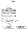
- step S1 the image processor 28 allows the imaging device 26 to pick up the image of the region including the screw portion T in the surface Ma of the object M, and thereby obtains the two-dimensional image of the object M.
- step S2 the image processor 28 operates to subject the obtained two-dimensional image to a filtering process.
- the imaging device 26 observes the screw portion T in an inclined direction, so that the image data of the hole H and the internal thread I, which should be subject to the filtering process, has an elliptical contour as viewed on a screen.
- the object M may be provided with various holes or the equivalents thereof, other than the screw portion T. Therefore, it is necessary to identify the image data of the hole H and the internal thread I, which should be subjected to the filtering process.
- an operator may previously set the positions and dimensions of a plurality of elliptical contours on the screen displaying the image from the imaging device 26, and may input the set positions and dimensions to the image processor 28.
- an additional image processing function may be provided to extract the data of the elliptical contour of the hole H and the internal thread I from the actual imaging data on the screen, and to identify the image corresponding to the extracted data as the image subject to the filtering process.
- the latter technique may appropriately deal with a case where the position and dimension of the screw portion T on the screen varies due to the fluctuation of the distance between the imaging device 26 and the object M.
- the filtering process performed by the image processor 28 includes an edge detection process.
- the output image data obtained by the filtering process includes edge data of the screw portion T.
- Filters referred to as Roberts, Sobel, Laplacian, or the like, filters may be employed as the filter for the edge detection process.
- step S3 the thread judging section (i.e., the robot controller 24 or the image processor 28) extracts the edge data obtained by the edge detection process, from the output image data through the filtering process, and acquires, by calculation, an evaluation value for the judgment of an amount of information of the edge data (e.g., a total number or a total area of pixels for displaying the edge). A proportion of the edge to the area of the obtained screw portion T on the screen may be used as the evaluation value.
- an evaluation value for the judgment of an amount of information of the edge data e.g., a total number or a total area of pixels for displaying the edge.
- a proportion of the edge to the area of the obtained screw portion T on the screen may be used as the evaluation value.
- pixels with a density gradient i.e., a varying rate between light and shade
- a predetermined threshold value i.e., a varying rate between light and shade
- [ evaluation value ] [ the number of pixels with density gradient larger than threshold ] / the total number of pixels of image of screw portion T
- step S4 the evaluation value described above is compared with a predetermined reference value. If the nut N is properly secured to the object M (Fig. 4), the light emitted from the illumination unit 30 is illuminated to the internal thread of the nut N and is diffusely reflected therefrom, and therefore the image data obtained by the imaging device 26 includes data of a plurality of bright elliptic striped patterns corresponding to the thread ridge of the internal thread. In contrast, if the nut N is not properly secured to the object M (Fig. 5), the light emitted from the illumination unit 30 passes through the hole H and, therefore, the image data obtained by the imaging device 26 includes data of a uniformly darkened region as the hole H.
- the evaluation value described above is larger than the predetermined reference value, it is judged that the nut N (i.e., the internal thread) exists and, on the other hand, when the evaluation value is smaller than the reference value, it is judged that the nut N (i.e., the internal thread) does not exist.
- the thread judging section i.e., the robot controller 24 or the image processor 28
- the screw portion inspection apparatus 20 can automatically judge, by image processing, whether the nut N is secured to the object M with the internal thread I being aligned with the hole H.
Landscapes
- Physics & Mathematics (AREA)
- General Physics & Mathematics (AREA)
- General Health & Medical Sciences (AREA)
- Chemical & Material Sciences (AREA)
- Analytical Chemistry (AREA)
- Biochemistry (AREA)
- Life Sciences & Earth Sciences (AREA)
- Health & Medical Sciences (AREA)
- Immunology (AREA)
- Pathology (AREA)
- Length Measuring Devices By Optical Means (AREA)
- Image Analysis (AREA)
- Image Processing (AREA)
Applications Claiming Priority (1)
| Application Number | Priority Date | Filing Date | Title |
|---|---|---|---|
| JP2005195135A JP2007010620A (ja) | 2005-07-04 | 2005-07-04 | ねじ部検査装置及びねじ部検査方法 |
Publications (2)
| Publication Number | Publication Date |
|---|---|
| EP1742016A1 true EP1742016A1 (de) | 2007-01-10 |
| EP1742016B1 EP1742016B1 (de) | 2008-10-22 |
Family
ID=36874706
Family Applications (1)
| Application Number | Title | Priority Date | Filing Date |
|---|---|---|---|
| EP06013734A Ceased EP1742016B1 (de) | 2005-07-04 | 2006-07-03 | Vorrichtung und Verfahren zur Überprüfung von Gewinden |
Country Status (5)
| Country | Link |
|---|---|
| US (1) | US20070002315A1 (de) |
| EP (1) | EP1742016B1 (de) |
| JP (1) | JP2007010620A (de) |
| CN (1) | CN1892677A (de) |
| DE (1) | DE602006003274D1 (de) |
Families Citing this family (20)
| Publication number | Priority date | Publication date | Assignee | Title |
|---|---|---|---|---|
| JP4758823B2 (ja) * | 2006-05-12 | 2011-08-31 | 日東精工株式会社 | めねじ成形部品の良否検査装置およびめねじ成形良否検査方法 |
| JP2008185462A (ja) * | 2007-01-30 | 2008-08-14 | Toyota Motor Corp | ねじ良否判定方法及びねじ良否判定装置 |
| ITMI20080967A1 (it) * | 2008-05-23 | 2009-11-24 | Salvatore Longoni | Metodo di progettazione e/o selezione di un dispositivo e/o materiale impiantabile in tessuti del corpo umano o animale e dispositivo e/o materiale cosi' ottenuto |
| SG158756A1 (en) * | 2008-07-10 | 2010-02-26 | Visionxtreme Pte Ltd | Hole inspection method and apparatus |
| JP5568947B2 (ja) * | 2009-10-21 | 2014-08-13 | アイシン精機株式会社 | ねじ穴または穴の内部表面欠陥検査装置 |
| EP2392896B1 (de) * | 2010-06-01 | 2019-11-27 | Tenaris Connections B.V. | Vorrichtung zur Messung der Gewindeparameter für Gewindeverbindungen |
| US8813610B2 (en) * | 2012-06-21 | 2014-08-26 | Tera Autotech Corporation | Automatic screw tightening apparatus |
| JP6278765B2 (ja) * | 2014-03-13 | 2018-02-14 | 株式会社キーレックス | ナット取付有無検査装置 |
| JP6297997B2 (ja) | 2015-03-18 | 2018-03-20 | ファナック株式会社 | ねじ穴の検査を行う数値制御装置 |
| CN105004275A (zh) * | 2015-07-21 | 2015-10-28 | 苏州佳祺仕信息科技有限公司 | 螺纹孔三ccd相机检测机构 |
| CN104990511A (zh) * | 2015-07-21 | 2015-10-21 | 苏州佳祺仕信息科技有限公司 | 螺纹孔结构质量检测方法 |
| JP6670562B2 (ja) * | 2015-07-22 | 2020-03-25 | 倉敷紡績株式会社 | 物品検査方法および装置 |
| CN105352386B (zh) * | 2015-09-07 | 2018-05-22 | 浙江工业大学 | 一种螺栓螺纹品质检测装置 |
| CN106053475B (zh) * | 2016-05-24 | 2018-10-23 | 浙江工业大学 | 基于主动式全景视觉的隧道病害全断面动态快速检测装置 |
| US10571260B2 (en) * | 2017-09-06 | 2020-02-25 | The Boeing Company | Automated rivet measurement system |
| CN108010027B (zh) * | 2017-12-27 | 2020-08-28 | 合肥市雅视智能科技有限公司 | 一种螺丝异常自动检测方法 |
| US11336831B2 (en) | 2018-07-06 | 2022-05-17 | Canon Kabushiki Kaisha | Image processing device, control method, and program storage medium |
| CN109341570B (zh) * | 2018-09-19 | 2020-09-08 | 中船重工鹏力(南京)智能装备系统有限公司 | 一种基于机器视觉的内螺纹检测方法及系统 |
| JP6885920B2 (ja) * | 2018-12-04 | 2021-06-16 | ファナック株式会社 | ネジ自動検査システム |
| TWI825932B (zh) * | 2022-08-19 | 2023-12-11 | 國立高雄科技大學 | 用於內螺紋瑕疵檢測之機構及方法 |
Citations (4)
| Publication number | Priority date | Publication date | Assignee | Title |
|---|---|---|---|---|
| US4315688A (en) * | 1979-08-08 | 1982-02-16 | Diffracto Ltd. | Electro-optical sensor systems for thread and hole inspection |
| DE4209417A1 (de) * | 1992-03-24 | 1993-10-07 | Hans Dieter Richter | Optische Prüfvorrichtung für Innengewinde |
| JP2003248813A (ja) * | 2002-02-25 | 2003-09-05 | Rozefu Technol:Kk | タップ穴検査方法およびその装置 |
| EP1544605A2 (de) * | 2003-12-19 | 2005-06-22 | Kamax-Werke Rudolf Kellermann GmbH & Co. KG | Verfahren und Vorrichtung zum Überprüfen eines Gewindes eines Verbindungselements auf Beschädigungen |
Family Cites Families (6)
| Publication number | Priority date | Publication date | Assignee | Title |
|---|---|---|---|---|
| DE3306194A1 (de) * | 1982-02-25 | 1983-09-08 | Mitsubishi Denki K.K., Tokyo | Verfahren zur pruefung von schraubenoberflaechen auf fehler und vorrichtung zu seiner durchfuehrung |
| JPS59141008A (ja) * | 1983-01-31 | 1984-08-13 | Nippon Kokan Kk <Nkk> | ねじ部検査装置 |
| JPS6396095A (ja) * | 1986-10-13 | 1988-04-26 | 株式会社キリンテクノシステム | 壜のねじ口部検査装置 |
| US5204911A (en) * | 1991-05-29 | 1993-04-20 | Nira Schwartz | Inspection method using unique templates and histogram analysis |
| US5521707A (en) * | 1991-08-21 | 1996-05-28 | Apeiron, Inc. | Laser scanning method and apparatus for rapid precision measurement of thread form |
| JP4269005B2 (ja) * | 2002-10-18 | 2009-05-27 | キリンテクノシステム株式会社 | ガラス壜の検査装置 |
-
2005
- 2005-07-04 JP JP2005195135A patent/JP2007010620A/ja active Pending
-
2006
- 2006-07-03 CN CNA2006101005417A patent/CN1892677A/zh active Pending
- 2006-07-03 EP EP06013734A patent/EP1742016B1/de not_active Ceased
- 2006-07-03 US US11/478,634 patent/US20070002315A1/en not_active Abandoned
- 2006-07-03 DE DE602006003274T patent/DE602006003274D1/de not_active Expired - Fee Related
Patent Citations (4)
| Publication number | Priority date | Publication date | Assignee | Title |
|---|---|---|---|---|
| US4315688A (en) * | 1979-08-08 | 1982-02-16 | Diffracto Ltd. | Electro-optical sensor systems for thread and hole inspection |
| DE4209417A1 (de) * | 1992-03-24 | 1993-10-07 | Hans Dieter Richter | Optische Prüfvorrichtung für Innengewinde |
| JP2003248813A (ja) * | 2002-02-25 | 2003-09-05 | Rozefu Technol:Kk | タップ穴検査方法およびその装置 |
| EP1544605A2 (de) * | 2003-12-19 | 2005-06-22 | Kamax-Werke Rudolf Kellermann GmbH & Co. KG | Verfahren und Vorrichtung zum Überprüfen eines Gewindes eines Verbindungselements auf Beschädigungen |
Non-Patent Citations (2)
| Title |
|---|
| LALIGANT O ET AL: "Wavelets transform in artificial vision inspection of threading", INDUSTRIAL ELECTRONICS, CONTROL, AND INSTRUMENTATION, 1993. PROCEEDINGS OF THE IECON '93., INTERNATIONAL CONFERENCE ON MAUI, HI, USA 15-19 NOV. 1993, NEW YORK, NY, USA,IEEE, 15 November 1993 (1993-11-15), pages 513 - 518, XP010108996, ISBN: 0-7803-0891-3 * |
| PATENT ABSTRACTS OF JAPAN vol. 2003, no. 12 5 December 2003 (2003-12-05) * |
Also Published As
| Publication number | Publication date |
|---|---|
| DE602006003274D1 (de) | 2008-12-04 |
| CN1892677A (zh) | 2007-01-10 |
| US20070002315A1 (en) | 2007-01-04 |
| JP2007010620A (ja) | 2007-01-18 |
| EP1742016B1 (de) | 2008-10-22 |
Similar Documents
| Publication | Publication Date | Title |
|---|---|---|
| EP1742016B1 (de) | Vorrichtung und Verfahren zur Überprüfung von Gewinden | |
| JP6360782B2 (ja) | ねじ類の検査方法 | |
| US20120293794A1 (en) | Method and apparatus for optical inspection, detection and analysis of double sided and wafer edge macro defects | |
| JP2005227217A (ja) | 基板検査装置及び検査方法 | |
| US20070046321A1 (en) | Apparatus and method for inspecting liquid crystal display | |
| TW201346250A (zh) | 光學複檢系統及其檢測方法 | |
| CN111443509A (zh) | 一种用于检测lcd液晶屏黑白斑和闪烁类缺陷的方法 | |
| EP2530457B1 (de) | Defektprüfgerät | |
| CN115436394A (zh) | 一种外观缺陷检测系统及方法 | |
| US7324685B2 (en) | Inspection systems and methods | |
| KR101622628B1 (ko) | 부품이 실장된 기판 검사방법 및 검사장치 | |
| US20070115462A1 (en) | Method for inspecting the quality criteria of flat textile structures embodied in a multi-layer form according to a contour | |
| EP4625311A1 (de) | Verfahren zur erkennung des materialplatzierungszustands in einer verpackungshülle | |
| CN110853031B (zh) | 汽车组合仪表指示灯点亮的排他检测方法 | |
| JP4655644B2 (ja) | 周期性パターンのムラ検査装置 | |
| KR101742260B1 (ko) | 자동이송식 하네스 비전 검사장치 | |
| JP4967245B2 (ja) | 周期性パターンのムラ検査装置及びムラ検査方法 | |
| KR100605027B1 (ko) | 카메라 또는 검사 대상의 이동 중 영상 획득에 의한영상검사방법 및 영상검사장치 | |
| JP2008026149A (ja) | 外観検査装置 | |
| JP6978131B1 (ja) | 外観検査方法及び外観検査装置 | |
| JP4794383B2 (ja) | ゴムホースの外観検査装置 | |
| JP3366760B2 (ja) | 溶液中の異物種類識別方法 | |
| Sidikova et al. | Inspection of the Cogwheel Using Virtual Instrumentation | |
| CN110057300A (zh) | 接头检测设备及其检测方法 | |
| JP3755370B2 (ja) | 半田フィレット検査方法 |
Legal Events
| Date | Code | Title | Description |
|---|---|---|---|
| PUAI | Public reference made under article 153(3) epc to a published international application that has entered the european phase |
Free format text: ORIGINAL CODE: 0009012 |
|
| AK | Designated contracting states |
Kind code of ref document: A1 Designated state(s): AT BE BG CH CY CZ DE DK EE ES FI FR GB GR HU IE IS IT LI LT LU LV MC NL PL PT RO SE SI SK TR |
|
| AX | Request for extension of the european patent |
Extension state: AL BA HR MK YU |
|
| 17P | Request for examination filed |
Effective date: 20070208 |
|
| 17Q | First examination report despatched |
Effective date: 20070319 |
|
| AKX | Designation fees paid |
Designated state(s): DE |
|
| GRAP | Despatch of communication of intention to grant a patent |
Free format text: ORIGINAL CODE: EPIDOSNIGR1 |
|
| GRAS | Grant fee paid |
Free format text: ORIGINAL CODE: EPIDOSNIGR3 |
|
| GRAA | (expected) grant |
Free format text: ORIGINAL CODE: 0009210 |
|
| AK | Designated contracting states |
Kind code of ref document: B1 Designated state(s): DE |
|
| REF | Corresponds to: |
Ref document number: 602006003274 Country of ref document: DE Date of ref document: 20081204 Kind code of ref document: P |
|
| RIN2 | Information on inventor provided after grant (corrected) |
Inventor name: ANDO, TOSHIYUKI Inventor name: WARASHINA, FUMIKAZU Inventor name: BAN, KAZUNORI |
|
| RIN2 | Information on inventor provided after grant (corrected) |
Inventor name: ANDO, TOSHIYUKI Inventor name: WARASHINA, FUMIKAZU Inventor name: BAN, KAZUNORI |
|
| PLBE | No opposition filed within time limit |
Free format text: ORIGINAL CODE: 0009261 |
|
| STAA | Information on the status of an ep patent application or granted ep patent |
Free format text: STATUS: NO OPPOSITION FILED WITHIN TIME LIMIT |
|
| 26N | No opposition filed |
Effective date: 20090723 |
|
| PG25 | Lapsed in a contracting state [announced via postgrant information from national office to epo] |
Ref country code: DE Free format text: LAPSE BECAUSE OF NON-PAYMENT OF DUE FEES Effective date: 20100202 |