EP1742012B1 - Tête de palpage - Google Patents
Tête de palpage Download PDFInfo
- Publication number
- EP1742012B1 EP1742012B1 EP06013335A EP06013335A EP1742012B1 EP 1742012 B1 EP1742012 B1 EP 1742012B1 EP 06013335 A EP06013335 A EP 06013335A EP 06013335 A EP06013335 A EP 06013335A EP 1742012 B1 EP1742012 B1 EP 1742012B1
- Authority
- EP
- European Patent Office
- Prior art keywords
- probe head
- probe
- generator
- voltage
- electrical energy
- Prior art date
- Legal status (The legal status is an assumption and is not a legal conclusion. Google has not performed a legal analysis and makes no representation as to the accuracy of the status listed.)
- Not-in-force
Links
Images


Classifications
-
- G—PHYSICS
- G01—MEASURING; TESTING
- G01B—MEASURING LENGTH, THICKNESS OR SIMILAR LINEAR DIMENSIONS; MEASURING ANGLES; MEASURING AREAS; MEASURING IRREGULARITIES OF SURFACES OR CONTOURS
- G01B21/00—Measuring arrangements or details thereof, where the measuring technique is not covered by the other groups of this subclass, unspecified or not relevant
- G01B21/02—Measuring arrangements or details thereof, where the measuring technique is not covered by the other groups of this subclass, unspecified or not relevant for measuring length, width, or thickness
- G01B21/04—Measuring arrangements or details thereof, where the measuring technique is not covered by the other groups of this subclass, unspecified or not relevant for measuring length, width, or thickness by measuring coordinates of points
- G01B21/047—Accessories, e.g. for positioning, for tool-setting, for measuring probes
-
- G—PHYSICS
- G01—MEASURING; TESTING
- G01B—MEASURING LENGTH, THICKNESS OR SIMILAR LINEAR DIMENSIONS; MEASURING ANGLES; MEASURING AREAS; MEASURING IRREGULARITIES OF SURFACES OR CONTOURS
- G01B5/00—Measuring arrangements characterised by the use of mechanical techniques
- G01B5/004—Measuring arrangements characterised by the use of mechanical techniques for measuring coordinates of points
- G01B5/008—Measuring arrangements characterised by the use of mechanical techniques for measuring coordinates of points using coordinate measuring machines
- G01B5/012—Contact-making feeler heads therefor
-
- H—ELECTRICITY
- H02—GENERATION; CONVERSION OR DISTRIBUTION OF ELECTRIC POWER
- H02K—DYNAMO-ELECTRIC MACHINES
- H02K7/00—Arrangements for handling mechanical energy structurally associated with dynamo-electric machines, e.g. structural association with mechanical driving motors or auxiliary dynamo-electric machines
- H02K7/18—Structural association of electric generators with mechanical driving motors, e.g. with turbines
- H02K7/1807—Rotary generators
- H02K7/1823—Rotary generators structurally associated with turbines or similar engines
-
- G—PHYSICS
- G01—MEASURING; TESTING
- G01B—MEASURING LENGTH, THICKNESS OR SIMILAR LINEAR DIMENSIONS; MEASURING ANGLES; MEASURING AREAS; MEASURING IRREGULARITIES OF SURFACES OR CONTOURS
- G01B2210/00—Aspects not specifically covered by any group under G01B, e.g. of wheel alignment, caliper-like sensors
- G01B2210/58—Wireless transmission of information between a sensor or probe and a control or evaluation unit
Definitions
- the invention relates to a probe according to claim 1, which is particularly suitable for a self-powered, battery-less operation.
- Tactile systems are used, for example, for determining the position of workpieces that are used in material processing machines, for. B. milling machines are clamped.
- These touch probes often include a stationary transceiver unit mounted on a stationary element of the material processing machine and a relatively mobile part, often referred to as a probe.
- the probe is usually attached to a movable element of the material processing machine, such as a milling spindle.
- the probe comprises a deflectable from a rest position stylus, or a deflectable probe element, which generates a switching signal from its rest position out at a deflection.
- Under the rest position of the probe element is a position of the probe element understood in which it has no contact with a workpiece. Upon contact of the probe element with the workpiece, the probe element is deflected out of its rest position.
- the corresponding switching signal is transmitted from the probe as an electromagnetic signal, in particular as an infrared signal, to the stationary transmitter-receiver unit.
- the output signals of the probe system are evaluated to determine the occurrence of switching signals (ie a deflection of the probe element).
- a cable connection between the probe and the stationary transmitter-receiver unit is therefore often not.
- Such a probe often has its power supply to a DC power source in the form of one or more batteries. There is a constant desire to increase the availability of such touch probes, which is why it is attempted to maximize the service life of the DC sources.
- a battery-powered probe is specified in which the life of the batteries to be extended by various measures, which ultimately improves the availability of the corresponding probe because of less downtime due to spent batteries.
- the probe next to a stylus comprises an electrical circuit, which are assigned, inter alia, a sensor unit, a CPU (Central Processing Unit) and a transmission stage.
- the probe has a generator of electrical energy for supplying power to said elements of the circuit.
- an electrical signal can be triggered by the sensor unit, which is convertible in the transmission stage into an emitable electromagnetic signal. This signal is then receivable by a stationary transceiver unit.
- the probe comprises a voltage converter, at the output of which an output voltage can be generated which is greater than the voltage applied to the voltage converter input voltage, wherein the output voltage for powering the transmission stage is used. In this way, optimal utilization of the electrical energy generated in the probe is possible.
- fluid is meant, for example, a gas, in particular air, or compressed air.
- a liquid such as a cooling liquid, as used for example in machine tools, can be used.
- the generator of electrical energy may include a turbomachine, which drives about a generator.
- the turbomachine is designed as a turbine.
- the turbine can advantageously be designed so that the fluid flows parallel to the axis of a rotating component, which is often designed as an impeller, or alternatively orthogonal (in the tangential direction) thereto.
- the turbine has a diagonal flow direction. That is, the fluid experiences a flow direction that has a tangential and axial directional component with respect to the axis of rotation of the rotating component.
- the probe has an energy storage, in particular for storing the generated electrical energy.
- an energy store may be, for example, a rechargeable accumulator or a buffer capacitor.
- buffer capacitors can here in an advantageous Such double-layer capacitors, also known as electrochemical double layer capacitors (EDLC) called capacitors, such as those sold under the brand names Goldcaps, Supercaps or Ultracaps.
- EDLC electrochemical double layer capacitors
- the energy generated can also be stored by mechanical means, such as by a spring or in the form of rotational energy of the rotating component of the turbomachine, which then works as a flywheel. This stored mechanical energy can later be converted into electrical energy.
- the invention also includes a probe without energy storage, in which then during the measuring operation of the generator of electrical energy is in operation.
- the rotating component may be mounted with a rolling bearing in the probe or by a sliding bearing, wherein the rotating component may be configured as a plastic part or as an aluminum part, which has a low coefficient of friction, so that advantageously in the construction of plastic a sliding bearing (as a bore in Pivot point of the rotating component) can be used.
- the storage can be lubricated by the fluid itself.
- gas for. As compressed air, a very low-friction air bearing can be used to support the rotating component in the probe.
- magnets are arranged on the rotating component of the turbomachine, which magnets can be designed, for example, as permanent magnets or electromagnets and opposed to stationary electrically conductive windings, for example in the form of a wire winding.
- the magnets which may for example be designed as permanent magnets or electromagnets, are integrated in the rotating component, in particular an impeller.
- the magnets may be arranged so that they do not protrude from the outer contour of the rotating component.
- At least one of the magnets is arranged so that the connecting line of the two poles has a direction component parallel to the axis of rotation of the rotating component.
- the field lines from the two poles of a magnet arranged in the rotating component with a directional component emerge from the magnet parallel to the axis of rotation of the rotating component.
- the stationary electrically conductive windings may be formed approximately in the form of a wire winding.
- the probe is configured so that an input voltage applied to the voltage converter corresponds to the output voltage of the generator of electrical energy or the output voltage of the energy store for storing the generated electrical energy.
- the probe can also be used when the generator of electrical energy is switched off.
- the output voltage at the energy storage is transformable by the voltage converter, so that the available use time is extended.
- the probe is configured such that during the operation of the generator of electrical energy, the power generated can be fed to both the energy storage and the consumers, so the sensor unit or the CPU or the transmission stage.
- the probe without any time delay immediately after the impeller is charged with the fluid to start its operation.
- the recharging time of the energy storage device then plays no role, since it is charged in parallel with the supply of the sensor unit, the CPU or the transmission stage.
- an electronic device can be provided in the probe that automatically opens a by-pass to the sensor unit, the CPU, or the transmission stage for part of the generated current at not fully charged energy storage. The then excessively generated power is used to charge the energy storage.
- the probe is constructed so that the effluent from the generator of electrical energy fluid, such as air, for cleaning a measuring point is used.
- the effluent from the generator of electrical energy fluid such as air
- corresponding flow channels are then provided in the probe, which direct the fluid to the measuring point without an unacceptably high pressure loss occurs.
- the fact that the outflowing fluid, such as the air, is not passed directly into the environment, but through the flow channels is also achieved with advantage that the operation of the generator of electrical energy is very quiet.
- the flow channels then act sound-absorbing.
- a receiving stage which can receive electromagnetic signals from a fixed transmitter-receiver unit and then causes corresponding reactions in the probe.
- the response to the received command is limited only to the functionality of enabling or disabling the probe.
- the activation is achieved by switching on the pressurized fluid, in particular by applying compressed air, to the probe.
- the button is then deactivated again, whereby, when using an energy store in the probe, depending on the installed storage capacity, a corresponding period can pass until the final deactivation.
- the generator of electrical energy comprises a turbine with an impeller rotatable about an axis, wherein magnets are attached to the impeller of the turbine, the stationary electrically conductive turns with axial distance opposite. Accordingly, there is an air gap between the magnets and the windings, which, relative to the axis of the impeller, has an axial extent. The air gap between the magnet and the impeller is thus advantageously located on one end face of the impeller.
- the solution according to the invention therefore makes it possible to increase the availability of a touch probe, or it can reduce standstill or set-up times. Because the probe can be designed so that it works completely self-sufficient energy, so that a change of batteries is not necessary at any time. The electrical energy generated in the probe is very well utilized.
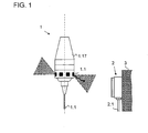
- a probe 1 is shown, which can be clamped by means of a clamping cone 1.17 in a machine tool.
- a cylindrical stylus 1.1 is provided on the probe 1, which has a probing ball at one end.
- the touch probe comprises a receiver unit 2, which is fixed to an immovable component 3 of the machine tool, so that therefore the probe head 1 is movable relative to the receiver unit 2, ie, relative to this.
- receiving elements 1.2 are distributed over the circumference of the probe 1 are provided, which are each secured offset by 60 ° along a circumferential line on the probe 1.
- electromagnetic signals in this case infrared signals, can be transmitted, which can be received by the receiver unit 2.
- FIG. 2 is a perspective view of the probe 1 in partial section without clamping cone 1.17 shown.
- the probe 1 comprises a cap 1.16, which has a fastening thread 1.161, to which the clamping cone 1.17 can be screwed. Furthermore, 1.16 four compressed air supply 1.162 are provided in the cap, which are as oblique holes through the wall the cap 1.16 are executed. Furthermore, the cap 1.16 has a central bore 1.163.
- Turbomachine 1.41 configured turbomachine comprises as a rotating component according to the FIG. 2 an impeller 1411, wherein the impeller is rotatable about an axis A, and in particular with a rolling bearing 1.412 relative to a fixed pin 1413 is rotatably mounted.
- the pin 1.413 rests in turn in the central bore 1.163 of the cap 1.16.
- the generator 1.42 consists of stationary electrically conductive windings, here in the form of windings 1.421 made of wire, in particular copper wire, and four magnets 1.422, which are integrated in the impeller 1.411.
- the magnets 1.422 are configured in all embodiments as permanent magnets.
- the usual symbolic representation for the generator 1.4 of electrical energy has been chosen for this, although in the exemplary embodiment shown there is no wave between the turbine 1.41 and the generator 1.42. Accordingly, 1.41 magnets 1.42 are fixed on the impeller 1.411 of the turbine, the stationary electrically conductive windings 1421 with axial distance, relative to the axis A of the impeller 1.411, opposite each other.
- a buffer capacitor 1.6 which is configured in the embodiment shown as a double-layer capacitor and is known under the brand name Goldcap. Such a buffer capacitor 1.6 can store comparatively much electrical energy at relatively low voltage.
- FIG. 2 Further down in the FIG. 2 is a circuit board to see 1.3, on which various electronic components of a circuit S are mounted.
- the probe 1 is clamped with its clamping cone 1.17 in a machine tool, which in turn is supplied with compressed air.
- the compressed air as a pressurized fluid, is fed through the clamping cone 1.17 in the compressed air supply 1.162.
- the compressed air is redirected so that it tangentially and with an axial direction component obliquely on the outer circumference of the impeller 1.411 and this thus set in rotation.
- an electrical voltage and an electric current are then produced in the windings 1421, that is, electrical energy is generated. This is used to charge the buffer capacitor 1.6.
- the switching on of the compressed air for flowing through the probe 1 is at the same time also the triggering event which activates the probe 1.
- the compressed air supply is switched off, so that it can not interfere with the measurement.
- the energy stored in the buffer capacitor 1.6 is used to supply the electronic components in the probe 1. If then the stylus 1.1 is deflected, ultimately, the deposition of a corresponding signal from the probe 1 to the receiver unit 2 is effected.
- FIG. 3 a further design variant of the probe according to the invention is shown.
- the turbine 1.41 is configured so that the compressed air has a tangential flow direction.
- the cap 1.16 'compressed air supply - not shown in detail in the figures -, which are aligned so that the compressed air flows tangentially to the impeller 1.411'.
- These holes are distributed at four points over the circumference of the cap 1.16 'and the impeller 1.411'.
- the probe 1 is shown in longitudinal section. Although also in the probe 1 according to FIG. 4 Flow channels are provided, which are configured such that the effluent from the turbine 1.41 fluid is usable for cleaning a measuring point, these flow channels are in the FIG. 4 not in the respective cutting planes and thus not visible.
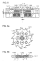
- FIG. 5 is a detail view of the longitudinal section according to FIG. 4 in the area of the impeller 1411 'and the windings 1421 shown.
- the pin 1413 'integral part of the cap 1.16' As well as in the construction according to FIG. 2 are here also attached to the impeller 1.411 'magnets 1.422, which are opposed to the stationary electrically conductive windings 1.421 with axial distance. In the FIG. 5 the distance is dimensioned with the symbol z.
- FIG. 6a is a plan view of the impeller 1.411 'shown.
- the impeller 1411 ' comprises thirteen blades.
- the impeller 1.411 ' is fed tangentially at four points distributed over the circumference compressed air. So that vibration conditions are avoided, the number of blades was chosen so that it is not integer divisible by the number of places where the compressed air is supplied.
- four magnets 1.422 are integrated in the impeller 1.411 '. The magnets 1.422 are installed in the impeller 1.411 'so that they do not protrude from the outer contour, or the end faces of the impeller 1.411'.
- the poles of the magnets 1.422 each have to the end face of the impeller 1.411 ', wherein circumferentially adjacent magnets 1.422 each have a reverse pole orientation (see also Fig. 6b ). In the execution according to FIG. 2 By the way, such an arrangement of the magnets 1422, as well as their pole orientation, is likewise present.
- a connecting line X of the poles N, S of the magnets 1.422 has a direction component parallel to the axis A of the impeller 1411, 1411 '.
- the connecting lines X are parallel to the axis A.
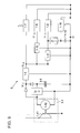
- the circuit S comprises the generator 1.4 of electrical energy consisting of the turbine 1.41 and the generator 1.42.
- the generator 1.4 of electrical energy is established. So that at high speed of the impeller 1.411 no unacceptably high DC voltage U 1.4 is formed, an overload protection circuit 1.15 is provided.
- the buffer capacitor 1.6 is charged. The negative pole of the generator 1.42 is connected to ground.
- the buffer capacitor 1.6 serves for the power supply of, inter alia, a sensor unit 1.8, a CPU 1.9 and a transmission stage 1.7.
- the circuit S comprises an RC-screening circuit, consisting of a resistor 1.13 and a capacitor 1.14 for supplying a receiving stage 1.18.
- the switching on of the probe can be effected exclusively by switching on the compressed air, instead of by setting a switch-on signal from the receiver unit 2.
- a voltage converter 1.5 is connected between the generator 1.4 of electrical energy or the buffer capacitor 1.6 and the transmission stage 1.7.
- the circuit S comprises two voltage limiters 1.11, 1.12, which supply output voltages U 1.11 , U 1.12 , which simultaneously serve as input voltage for the sensor unit 1.8 or for the CPU 1.9, respectively.
- a digital signal is generated in the sensor unit 1.8 (change of a voltage level from high to low). This signal is forwarded to the CPU 1.9 and further processed there. The further processed by the CPU signal is then passed to the transmission stage 1.7, which generates the transmission signal in the form of electromagnetic radiation or signals.
- the electromagnetic signals are formed as infrared signals, but it can also be used, for example, radio signals.
- the signals are received by the stationary transceiver unit 2. Inside the receiver unit 2, the infrared signals are converted into electrical signals and processed. Finally, the processed electrical signals arrive via a cable 2.1 in a stationary sequential electronics, where they are further processed.
- the DC voltage U 1.4 may fall below a value that is necessary for the operation of the probe 1 after a certain period of operation.
- the transmission stage requires 1.7 for proper operation, an input voltage U 1.5 of more than 5 V, in the presented embodiment, the operating target voltage for the transmission stage 1.7 at 5.5 V.
- the touch probe can continue to operate even with relatively low DC voltage U 1.4 . As a result, the possible operating time of the probe 1 is increased.
- the voltage converter 1.5 ensures that the voltage U 1.5 is at least 5 V. Therefore, it is also ensured that the input voltage U 1.12 of the sensor unit 1.8 can be reduced to the required 2.8 V by the voltage limiter 1.12.
- the DC voltage U 1.4 both at the voltage converter 1.5 and at a further voltage converter 1.5 'to.
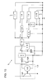
- FIG. 9 a further variant of the circuit S is shown.
- a voltage regulator 1.15 ' is used to protect against overload. This makes it possible for the generated current to be fed to both the energy store 1.6 and the sensor unit 1.8, the CPU 1.9 and the transmitting stage 1.7 during the generation of electrical energy. This can ensure that the sensor unit 1.8, the CPU 1.9 and the transmission stage 1.7 can work immediately after switching on the compressed air. A delay by the charging process of the buffer capacitor 1.6 is then excluded. On the other hand, by the operation of the turbine 1.41 and the generator 1.42 so much power is generated that in addition to the supply of the sensor unit 1.8, the CPU 1.9 and the transmission stage 1.7 and the buffer capacitor 1.6 can be charged controlled by the voltage regulator 1.15 '.
- FIG. 10 a further variant of the circuit S is shown.
- Parallel to the buffer capacitor 1.6 here is a control 1.19 connected.
- the control element 1.19 sets a short-circuit transistor 1.20 in a current-permeable state so that the windings 1421 of the generator 1.42 are short-circuited. In this way, the load is increased for the generator 1.42.
- This has the consequence that the speed of the impeller 1.411, 1.411 'is reduced.
- the maximum speed of the impeller 1.411, 1.411 ' can be limited, or it can be too high speeds of the impeller 1.411, 1.411' avoided.
- a so-called SEPIC element can also be used for the same purpose.
- the SEPIC element has the property that the predetermined output voltage is not changed in the upward direction, that is, if an output voltage of 5.5 V is specified for a SEPIC element, this voltage is not undershot if the corresponding input voltage is lower than 5.5V, but it will not be exceeded if the corresponding input voltage is greater than 5.5V. This behavior is advantageous because it results in a reduction of the power loss, or to increase the efficiency of the circuit S.
Landscapes
- Physics & Mathematics (AREA)
- General Physics & Mathematics (AREA)
- Engineering & Computer Science (AREA)
- Power Engineering (AREA)
- Connection Of Motors, Electrical Generators, Mechanical Devices, And The Like (AREA)
- Measurement Of Length, Angles, Or The Like Using Electric Or Magnetic Means (AREA)
- Surgical Instruments (AREA)
- Arrangements For Transmission Of Measured Signals (AREA)
- Electrical Discharge Machining, Electrochemical Machining, And Combined Machining (AREA)
- Length Measuring Devices With Unspecified Measuring Means (AREA)
Claims (14)
- Tête de palpeur (1) avec un palpeur (1.1), ladite tête de palpeur (1) comprenant :- une unité de détection (1.8),- une unité centrale de traitement (1.9),- une phase de transmission (1.7), et- un générateur (1.4) d'énergie électrique pour l'alimentation en énergie de l'unité de détection (1.8), de l'unité centrale de traitement (1.9) et de la phase de transmission (1.7),dans laquelle, lors de la déviation du palpeur (1.1), un signal électrique peut être déclenché à partir de l'unité de détection (1.8), lequel peut être converti en un signal électromagnétique dans la phase de transmission (1.7), et
le générateur (1.4) d'énergie électrique peut être activé à l'aide d'un fluide sous pression, où- la tête de palpeur (1) comprend en outre un transformateur de tension (1.5), à la sortie duquel peut être produite une tension de sortie (U1.5), qui est supérieure à la tension d'entrée (U1.4) appliquée au transformateur de tension (1.5), la tension de sortie (U1.5) servant à l'alimentation en énergie de la phase de transmission (1.7). - Tête de palpeur (1) selon la revendication 1, dans laquelle la tête de palpeur (1) comprend un réservoir d'énergie (1.6) pour le stockage de l'énergie électrique produite.
- Tête de palpeur (1) selon la revendication 2, dans laquelle le réservoir d'énergie (1.6) est un condensateur.
- Tête de palpeur (1) selon la revendication 2 ou 3, dans laquelle la tension d'entrée (U1.4) appliquée au transformateur de tension (1.5) correspond à- la tension de sortie (U1.4) du générateur (1.4) d'énergie électrique, ou- la tension de sortie (U1.4) du réservoir d'énergie (1.6).
- Tête de palpeur (1) selon l'une des revendications précédentes, dans laquelle celle-ci est configurée de telle manière, que pendant le fonctionnement du générateur (1.4) d'énergie électrique, le courant produit peut être alimenté aussi bien vers le réservoir d'énergie (1.6) que vers l'unité de détection (1.8), ou encore vers l'unité centrale de traitement (1.9) ou la phase de transmission (1.7).
- Tête de palpeur (1) selon l'une des revendications précédentes, dans laquelle le générateur (1.4) d'énergie électrique comprend une turbomachine (1.41).
- Tête de palpeur (1) selon la revendication 6, dans laquelle la turbomachine (1.41) est conçue comme une turbine.
- Tête de palpeur (1) selon la revendication 7, dans laquelle la turbine (1.41) est configurée de telle manière, que le fluide présente une direction d'écoulement tangentielle.
- Tête de palpeur (1) selon la revendication 6, 7 ou 8, dans laquelle des aimants (1.422), en particulier des aimants permanents, sont montés sur une pièce rotative de la turbomachine (1.41), tout en étant opposés à des spires électriquement conductrices (1.421) stationnaires.
- Tête de palpeur (1) selon la revendication 8, 9 ou 10, dans laquelle le générateur (1.4) d'énergie électrique comprend une turbine (1.41) avec un rotor (1.411, 1.411') rotatif autour d'un axe (A), dans laquelle des aimants (1.422) opposés aux spires électriquement conductrices (1.421) stationnaires, avec un écart axial (z), sont fixés au rotor (1.411, 1.411') de la turbine (1.41).
- Tête de turbine (1) selon la revendication 10, dans laquelle la ligne de liaison (X) des pôles (N, S) de l'un des aimants (1.422) comporte une composante directionnelle parallèle à l'axe (A) du rotor (1.411, 1.411').
- Tête de palpeur (1) selon l'une des revendications 6 à 11, dans laquelle celle-ci comporte une électronique de commande (1.19), par laquelle les spires électriquement conductrices (1.421) stationnaires peuvent être court-circuitées, pour limiter le nombre de tours de la turbomachine (1.41).
- Tête de palpeur (1) selon l'une des revendications précédentes, dans laquelle le fluide, en particulier de l'air comprimé, sort du générateur (1.4) d'énergie électrique, et des canaux d'écoulement correspondants dans la tête de palpeur (1) sont configurés de telle manière, que le fluide en écoulement peut être utilisé pour le nettoyage d'un point de mesurage.
- Tête de palpeur (1) selon l'une des revendications précédentes, dans laquelle celle-ci est configurée de telle manière qu'une activation de la tête de palpeur (1) peut être atteinte par l'application du fluide sous pression sur la tête de palpeur.
Applications Claiming Priority (3)
| Application Number | Priority Date | Filing Date | Title |
|---|---|---|---|
| DE102005031994 | 2005-07-08 | ||
| DE102006024491A DE102006024491A1 (de) | 2005-07-08 | 2006-05-26 | Tastkopf |
| DE102006024492A DE102006024492A1 (de) | 2005-07-08 | 2006-05-26 | Tastkopf |
Publications (3)
| Publication Number | Publication Date |
|---|---|
| EP1742012A2 EP1742012A2 (fr) | 2007-01-10 |
| EP1742012A3 EP1742012A3 (fr) | 2010-02-17 |
| EP1742012B1 true EP1742012B1 (fr) | 2010-11-03 |
Family
ID=36791615
Family Applications (2)
| Application Number | Title | Priority Date | Filing Date |
|---|---|---|---|
| EP06013334A Not-in-force EP1742011B1 (fr) | 2005-07-08 | 2006-06-28 | Tête de palpage |
| EP06013335A Not-in-force EP1742012B1 (fr) | 2005-07-08 | 2006-06-28 | Tête de palpage |
Family Applications Before (1)
| Application Number | Title | Priority Date | Filing Date |
|---|---|---|---|
| EP06013334A Not-in-force EP1742011B1 (fr) | 2005-07-08 | 2006-06-28 | Tête de palpage |
Country Status (4)
| Country | Link |
|---|---|
| US (1) | US7464483B2 (fr) |
| EP (2) | EP1742011B1 (fr) |
| AT (2) | ATE487107T1 (fr) |
| DE (2) | DE502006008214D1 (fr) |
Families Citing this family (16)
| Publication number | Priority date | Publication date | Assignee | Title |
|---|---|---|---|---|
| JP2009053052A (ja) * | 2007-08-27 | 2009-03-12 | Mitsutoyo Corp | 形状測定機及びその測定子 |
| DE102007054838A1 (de) * | 2007-11-16 | 2009-05-20 | Dr. Johannes Heidenhain Gmbh | Tastsystem und Verfahren zum Betrieb eines Tastsystems |
| JP4291394B1 (ja) * | 2008-03-12 | 2009-07-08 | ファナック株式会社 | 接触式計測装置 |
| EP2112461B1 (fr) | 2008-04-24 | 2012-10-24 | Hexagon Metrology AB | Palpeur de mesure autoalimenté |
| JP5262630B2 (ja) * | 2008-12-01 | 2013-08-14 | 富士通株式会社 | セルフテスト回路を有するクロック生成回路 |
| JP6010045B2 (ja) | 2011-01-19 | 2016-10-19 | レニショウ パブリック リミテッド カンパニーRenishaw Public Limited Company | 工作機械装置用のアナログ測定プローブおよび操作方法 |
| DE102011084755A1 (de) | 2011-03-24 | 2012-09-27 | Dr. Johannes Heidenhain Gmbh | Tastkopf und Verfahren zum Betreiben eines Tastkopfs |
| DE102011100467B3 (de) * | 2011-05-02 | 2012-07-05 | Carl Zeiss Industrielle Messtechnik Gmbh | Messkopf für ein Koordinatenmessgerät zum Bestimmen von Raumkoordinaten an einem Messobjekt |
| EP2920549B1 (fr) * | 2012-11-14 | 2020-01-08 | Renishaw Plc. | Procédé et appareil pour la mesure d'une pièce avec une machine-outil |
| US20150125230A1 (en) * | 2013-11-01 | 2015-05-07 | Lockheed Martin Corporation | Apparatus for an on-tool power supply |
| EP3524587A1 (fr) | 2015-08-21 | 2019-08-14 | SABIC Global Technologies B.V. | Procédé de production de btx à partir d'un mélange d'hydrocarbures c5-c12 |
| DE102016012726A1 (de) * | 2016-10-24 | 2018-04-26 | Blum-Novotest Gmbh | Messsystem zur Messung an Werkzeugen in einer Werkzeugmaschine |
| EP3688404B1 (fr) * | 2017-09-29 | 2023-06-07 | Mitutoyo Corporation | Configuration de dispositif de mesure compact pour intégrer des circuits complexes |
| US12179276B2 (en) * | 2021-01-20 | 2024-12-31 | Iscar, Ltd. | Rotary cutting tool having an energy harvesting arrangement |
| DE102021128314A1 (de) | 2021-10-29 | 2023-05-04 | Blum-Novotest Gmbh | Rundlaufüberwachungsmodule und Rundlaufüberwachungsverfahren für ein im Betrieb zu rotierendes Werkzeug |
| US11821811B2 (en) * | 2022-02-04 | 2023-11-21 | Pratt & Whitney Canada Corp. | Fluid measurement system for an aircraft gas turbine engine and method for operating same |
Family Cites Families (23)
| Publication number | Priority date | Publication date | Assignee | Title |
|---|---|---|---|---|
| US4339714A (en) * | 1978-07-07 | 1982-07-13 | Rolls Royce Limited | Probe having passive means transmitting an output signal by reactive coupling |
| CH660421A5 (de) * | 1982-12-18 | 1987-04-15 | Maag Zahnraeder & Maschinen Ag | Zahnmesstaster fuer zahnradmessmaschine. |
| US4513507A (en) * | 1983-09-02 | 1985-04-30 | Bendix Automation Company | Contact sensing probe for a measuring apparatus |
| GB8503355D0 (en) * | 1985-02-09 | 1985-03-13 | Renishaw Plc | Sensing surface of object |
| US4654956A (en) * | 1985-04-16 | 1987-04-07 | Protocad, Inc. | Drill apparatus for use with computer controlled plotter |
| DE68916463T2 (de) * | 1988-04-12 | 1994-11-17 | Renishaw Plc | Signalübertragungssystem für Werkzeugmaschinen, Inspektionsmaschinen und dergleichen. |
| DE3813949A1 (de) * | 1988-04-26 | 1989-11-09 | Heidenhain Gmbh Dr Johannes | Vorrichtung zur induktiven signaluebertragung bei tastkoepfen |
| JPH03223602A (ja) * | 1990-01-29 | 1991-10-02 | Tokyo Seimitsu Co Ltd | 自動計測プローブ |
| DE69127277T2 (de) * | 1990-03-23 | 1998-01-29 | Geotronics Ab | Analoger abweichungssensor |
| FR2715222B1 (fr) * | 1994-01-14 | 1996-04-05 | Giat Ind Sa | Compteur auto-alimenté. |
| US5564872A (en) * | 1994-03-21 | 1996-10-15 | Veil; Wilfried | Implement for machine tools and process for generating electric power in one such implement |
| DE4424225A1 (de) * | 1994-07-09 | 1996-01-11 | Zeiss Carl Fa | Tastkopf für Koordinatenmeßgeräte |
| IT1309248B1 (it) * | 1999-05-13 | 2002-01-16 | Marposs Spa | Sistema per rilevare dimensioni lineari di pezzi meccanici, con unita' di ricetrasmissione di segnali via etere |
| SE523573C2 (sv) * | 2000-12-22 | 2004-04-27 | Atlas Copco Tools Ab | Tryckluftdrivet maskinverktyg. |
| ATE407389T1 (de) * | 2001-02-02 | 2008-09-15 | Renishaw Plc | Durch biegung des messfühlers konfigurierbare messsonde für eine werkzeugmaschine |
| JP2003170328A (ja) * | 2001-11-30 | 2003-06-17 | Toshiba Mach Co Ltd | 工具、工具ホルダおよび工作機械 |
| JP4959111B2 (ja) * | 2002-04-20 | 2012-06-20 | レニショウ パブリック リミテッド カンパニー | 機械の適合構造 |
| DE10303551A1 (de) * | 2003-01-29 | 2004-08-12 | Dr. Johannes Heidenhain Gmbh | Verfahren zum Übertragen von Steuerbefehlen von einem Sendeelement zu einem Messtaster |
| GB0308149D0 (en) * | 2003-04-09 | 2003-05-14 | Renishaw Plc | Probe for sensing the position of an object |
| GB0325353D0 (en) * | 2003-10-30 | 2003-12-03 | Renishaw Plc | Machine adaptation |
| DE102004003487A1 (de) | 2004-01-23 | 2005-08-11 | Dr. Johannes Heidenhain Gmbh | Tastsystem und Verfahren zum Betreiben eines Tastsystems |
| DE102004011730A1 (de) * | 2004-03-05 | 2005-09-22 | Carl Zeiss Industrielle Messtechnik Gmbh | Tastkopf für ein Koordinatenmessgerät |
| DE102006054978A1 (de) * | 2006-11-22 | 2008-05-29 | Dr. Johannes Heidenhain Gmbh | Tastsystem |
-
2006
- 2006-06-28 DE DE502006008214T patent/DE502006008214D1/de active Active
- 2006-06-28 AT AT06013334T patent/ATE487107T1/de active
- 2006-06-28 AT AT06013335T patent/ATE487108T1/de active
- 2006-06-28 DE DE502006008215T patent/DE502006008215D1/de active Active
- 2006-06-28 EP EP06013334A patent/EP1742011B1/fr not_active Not-in-force
- 2006-06-28 EP EP06013335A patent/EP1742012B1/fr not_active Not-in-force
- 2006-07-10 US US11/484,272 patent/US7464483B2/en not_active Expired - Fee Related
Also Published As
| Publication number | Publication date |
|---|---|
| EP1742011A3 (fr) | 2010-02-17 |
| US20070006473A1 (en) | 2007-01-11 |
| ATE487107T1 (de) | 2010-11-15 |
| US7464483B2 (en) | 2008-12-16 |
| DE502006008215D1 (de) | 2010-12-16 |
| EP1742011B1 (fr) | 2010-11-03 |
| ATE487108T1 (de) | 2010-11-15 |
| EP1742011A2 (fr) | 2007-01-10 |
| EP1742012A2 (fr) | 2007-01-10 |
| DE502006008214D1 (de) | 2010-12-16 |
| EP1742012A3 (fr) | 2010-02-17 |
Similar Documents
| Publication | Publication Date | Title |
|---|---|---|
| EP1742012B1 (fr) | Tête de palpage | |
| EP1878535B1 (fr) | Système de capteur pour machines-outils | |
| DE69928895T2 (de) | Hochgeschwindigkeitsbohrspindel mit einer hin- und hergehenden keramischen Welle und einem doppeltgreifenden Zentrifugalspannfutter | |
| EP2049302B1 (fr) | Dispositif de roulement et d'entraînement d'une table circulaire | |
| EP3028804B1 (fr) | Agencement de transmission, en particulier la transmission d'énergie et/ou de signal | |
| DE102011105306A1 (de) | Tragbares Werkzeug mit drahtloser Messwertübertragung | |
| EP0972868A2 (fr) | Palier pour une machine de filature à bout ouvert | |
| EP1207299A2 (fr) | Eolienne avec palier magnétique | |
| WO2007093465A1 (fr) | Machine électrique munie d'un dispositif pour éviter les courants de palier dommageables et procédé correspondant | |
| DE102012201347A1 (de) | Elektromaschine, insbesondere Elektromotor für ein Kraftfahrzeug | |
| DE102018215796A1 (de) | Positionserfassungssystem und Verfahren zur Erfassung einer Bewegung einer Maschine | |
| DE10302531B4 (de) | Messeinrichtung und Messverfahren für Elektromotoren | |
| EP2843784A2 (fr) | Commutation d'entraînement pour un moteur monté sur coussin d'air | |
| DE102009041340A1 (de) | Schäleinrichtung und Schälmaschine | |
| DE102016119821A1 (de) | Motorspindel | |
| DE102006024492A1 (de) | Tastkopf | |
| DE102006024491A1 (de) | Tastkopf | |
| EP2699916B1 (fr) | Dispositif de surveillance pour une machine asynchrone à double alimentation | |
| DE102023126766A1 (de) | Vorrichtung und Verfahren zur Bestimmung einer Zustandsgröße eines Motorlagers | |
| DE102016208341A1 (de) | Dampfturbinenanlage mit Magnetlagerung | |
| DE102010005557A1 (de) | Werkstücktisch für Werkzeugmaschinen zur spanenden Drehbearbeitung von Werkstücken | |
| EP1557639B1 (fr) | Système palpeur et procédé pour le faire fonctionner | |
| EP4137699B1 (fr) | Appareil à vide et procédé de fonctionnement d'un tel appareil à vide | |
| WO2008098846A2 (fr) | Dispositif électrique d'entraînement direct, en particulier pour un plateau rotatif | |
| DE102017118771A1 (de) | Abtriebsstation für die Betätigung einer Klappe an einem Flugzeugflügel und Flugzeug mit solchen Abtriebsstationen |
Legal Events
| Date | Code | Title | Description |
|---|---|---|---|
| PUAI | Public reference made under article 153(3) epc to a published international application that has entered the european phase |
Free format text: ORIGINAL CODE: 0009012 |
|
| AK | Designated contracting states |
Kind code of ref document: A2 Designated state(s): AT BE BG CH CY CZ DE DK EE ES FI FR GB GR HU IE IS IT LI LT LU LV MC NL PL PT RO SE SI SK TR |
|
| AX | Request for extension of the european patent |
Extension state: AL BA HR MK YU |
|
| 17P | Request for examination filed |
Effective date: 20091126 |
|
| PUAL | Search report despatched |
Free format text: ORIGINAL CODE: 0009013 |
|
| AK | Designated contracting states |
Kind code of ref document: A3 Designated state(s): AT BE BG CH CY CZ DE DK EE ES FI FR GB GR HU IE IS IT LI LT LU LV MC NL PL PT RO SE SI SK TR |
|
| AX | Request for extension of the european patent |
Extension state: AL BA HR MK RS |
|
| GRAP | Despatch of communication of intention to grant a patent |
Free format text: ORIGINAL CODE: EPIDOSNIGR1 |
|
| RIC1 | Information provided on ipc code assigned before grant |
Ipc: G01B 5/012 20060101AFI20100723BHEP |
|
| GRAS | Grant fee paid |
Free format text: ORIGINAL CODE: EPIDOSNIGR3 |
|
| GRAA | (expected) grant |
Free format text: ORIGINAL CODE: 0009210 |
|
| AKX | Designation fees paid |
Designated state(s): AT BE BG CH CY CZ DE DK EE ES FI FR GB GR HU IE IS IT LI LT LU LV MC NL PL PT RO SE SI SK TR |
|
| AK | Designated contracting states |
Kind code of ref document: B1 Designated state(s): AT BE BG CH CY CZ DE DK EE ES FI FR GB GR HU IE IS IT LI LT LU LV MC NL PL PT RO SE SI SK TR |
|
| REG | Reference to a national code |
Ref country code: GB Ref legal event code: FG4D Free format text: NOT ENGLISH |
|
| REG | Reference to a national code |
Ref country code: CH Ref legal event code: NV Representative=s name: ICB INGENIEURS CONSEILS EN BREVETS SA Ref country code: CH Ref legal event code: EP |
|
| REG | Reference to a national code |
Ref country code: IE Ref legal event code: FG4D Free format text: LANGUAGE OF EP DOCUMENT: GERMAN |
|
| REF | Corresponds to: |
Ref document number: 502006008215 Country of ref document: DE Date of ref document: 20101216 Kind code of ref document: P |
|
| REG | Reference to a national code |
Ref country code: NL Ref legal event code: VDEP Effective date: 20101103 |
|
| LTIE | Lt: invalidation of european patent or patent extension |
Effective date: 20101103 |
|
| PG25 | Lapsed in a contracting state [announced via postgrant information from national office to epo] |
Ref country code: LT Free format text: LAPSE BECAUSE OF FAILURE TO SUBMIT A TRANSLATION OF THE DESCRIPTION OR TO PAY THE FEE WITHIN THE PRESCRIBED TIME-LIMIT Effective date: 20101103 |
|
| REG | Reference to a national code |
Ref country code: IE Ref legal event code: FD4D |
|
| PG25 | Lapsed in a contracting state [announced via postgrant information from national office to epo] |
Ref country code: BG Free format text: LAPSE BECAUSE OF FAILURE TO SUBMIT A TRANSLATION OF THE DESCRIPTION OR TO PAY THE FEE WITHIN THE PRESCRIBED TIME-LIMIT Effective date: 20110203 Ref country code: FI Free format text: LAPSE BECAUSE OF FAILURE TO SUBMIT A TRANSLATION OF THE DESCRIPTION OR TO PAY THE FEE WITHIN THE PRESCRIBED TIME-LIMIT Effective date: 20101103 Ref country code: SE Free format text: LAPSE BECAUSE OF FAILURE TO SUBMIT A TRANSLATION OF THE DESCRIPTION OR TO PAY THE FEE WITHIN THE PRESCRIBED TIME-LIMIT Effective date: 20101103 Ref country code: IS Free format text: LAPSE BECAUSE OF FAILURE TO SUBMIT A TRANSLATION OF THE DESCRIPTION OR TO PAY THE FEE WITHIN THE PRESCRIBED TIME-LIMIT Effective date: 20110303 Ref country code: NL Free format text: LAPSE BECAUSE OF FAILURE TO SUBMIT A TRANSLATION OF THE DESCRIPTION OR TO PAY THE FEE WITHIN THE PRESCRIBED TIME-LIMIT Effective date: 20101103 Ref country code: LV Free format text: LAPSE BECAUSE OF FAILURE TO SUBMIT A TRANSLATION OF THE DESCRIPTION OR TO PAY THE FEE WITHIN THE PRESCRIBED TIME-LIMIT Effective date: 20101103 Ref country code: PT Free format text: LAPSE BECAUSE OF FAILURE TO SUBMIT A TRANSLATION OF THE DESCRIPTION OR TO PAY THE FEE WITHIN THE PRESCRIBED TIME-LIMIT Effective date: 20110303 Ref country code: SI Free format text: LAPSE BECAUSE OF FAILURE TO SUBMIT A TRANSLATION OF THE DESCRIPTION OR TO PAY THE FEE WITHIN THE PRESCRIBED TIME-LIMIT Effective date: 20101103 |
|
| PG25 | Lapsed in a contracting state [announced via postgrant information from national office to epo] |
Ref country code: GR Free format text: LAPSE BECAUSE OF FAILURE TO SUBMIT A TRANSLATION OF THE DESCRIPTION OR TO PAY THE FEE WITHIN THE PRESCRIBED TIME-LIMIT Effective date: 20110204 |
|
| PG25 | Lapsed in a contracting state [announced via postgrant information from national office to epo] |
Ref country code: CZ Free format text: LAPSE BECAUSE OF FAILURE TO SUBMIT A TRANSLATION OF THE DESCRIPTION OR TO PAY THE FEE WITHIN THE PRESCRIBED TIME-LIMIT Effective date: 20101103 Ref country code: EE Free format text: LAPSE BECAUSE OF FAILURE TO SUBMIT A TRANSLATION OF THE DESCRIPTION OR TO PAY THE FEE WITHIN THE PRESCRIBED TIME-LIMIT Effective date: 20101103 Ref country code: IE Free format text: LAPSE BECAUSE OF FAILURE TO SUBMIT A TRANSLATION OF THE DESCRIPTION OR TO PAY THE FEE WITHIN THE PRESCRIBED TIME-LIMIT Effective date: 20101103 Ref country code: ES Free format text: LAPSE BECAUSE OF FAILURE TO SUBMIT A TRANSLATION OF THE DESCRIPTION OR TO PAY THE FEE WITHIN THE PRESCRIBED TIME-LIMIT Effective date: 20110214 |
|
| PG25 | Lapsed in a contracting state [announced via postgrant information from national office to epo] |
Ref country code: RO Free format text: LAPSE BECAUSE OF FAILURE TO SUBMIT A TRANSLATION OF THE DESCRIPTION OR TO PAY THE FEE WITHIN THE PRESCRIBED TIME-LIMIT Effective date: 20101103 Ref country code: SK Free format text: LAPSE BECAUSE OF FAILURE TO SUBMIT A TRANSLATION OF THE DESCRIPTION OR TO PAY THE FEE WITHIN THE PRESCRIBED TIME-LIMIT Effective date: 20101103 Ref country code: PL Free format text: LAPSE BECAUSE OF FAILURE TO SUBMIT A TRANSLATION OF THE DESCRIPTION OR TO PAY THE FEE WITHIN THE PRESCRIBED TIME-LIMIT Effective date: 20101103 Ref country code: DK Free format text: LAPSE BECAUSE OF FAILURE TO SUBMIT A TRANSLATION OF THE DESCRIPTION OR TO PAY THE FEE WITHIN THE PRESCRIBED TIME-LIMIT Effective date: 20101103 |
|
| PLBE | No opposition filed within time limit |
Free format text: ORIGINAL CODE: 0009261 |
|
| STAA | Information on the status of an ep patent application or granted ep patent |
Free format text: STATUS: NO OPPOSITION FILED WITHIN TIME LIMIT |
|
| 26N | No opposition filed |
Effective date: 20110804 |
|
| REG | Reference to a national code |
Ref country code: DE Ref legal event code: R097 Ref document number: 502006008215 Country of ref document: DE Effective date: 20110804 |
|
| BERE | Be: lapsed |
Owner name: DR. JOHANNES HEIDENHAIN G.M.B.H. Effective date: 20110630 |
|
| REG | Reference to a national code |
Ref country code: FR Ref legal event code: ST Effective date: 20120229 |
|
| PG25 | Lapsed in a contracting state [announced via postgrant information from national office to epo] |
Ref country code: BE Free format text: LAPSE BECAUSE OF NON-PAYMENT OF DUE FEES Effective date: 20110630 |
|
| PG25 | Lapsed in a contracting state [announced via postgrant information from national office to epo] |
Ref country code: FR Free format text: LAPSE BECAUSE OF NON-PAYMENT OF DUE FEES Effective date: 20110630 |
|
| REG | Reference to a national code |
Ref country code: AT Ref legal event code: MM01 Ref document number: 487108 Country of ref document: AT Kind code of ref document: T Effective date: 20110628 |
|
| PG25 | Lapsed in a contracting state [announced via postgrant information from national office to epo] |
Ref country code: AT Free format text: LAPSE BECAUSE OF NON-PAYMENT OF DUE FEES Effective date: 20110628 |
|
| PG25 | Lapsed in a contracting state [announced via postgrant information from national office to epo] |
Ref country code: MC Free format text: LAPSE BECAUSE OF NON-PAYMENT OF DUE FEES Effective date: 20110630 |
|
| PG25 | Lapsed in a contracting state [announced via postgrant information from national office to epo] |
Ref country code: LU Free format text: LAPSE BECAUSE OF NON-PAYMENT OF DUE FEES Effective date: 20110628 Ref country code: CY Free format text: LAPSE BECAUSE OF FAILURE TO SUBMIT A TRANSLATION OF THE DESCRIPTION OR TO PAY THE FEE WITHIN THE PRESCRIBED TIME-LIMIT Effective date: 20101103 |
|
| PG25 | Lapsed in a contracting state [announced via postgrant information from national office to epo] |
Ref country code: TR Free format text: LAPSE BECAUSE OF FAILURE TO SUBMIT A TRANSLATION OF THE DESCRIPTION OR TO PAY THE FEE WITHIN THE PRESCRIBED TIME-LIMIT Effective date: 20101103 |
|
| PG25 | Lapsed in a contracting state [announced via postgrant information from national office to epo] |
Ref country code: HU Free format text: LAPSE BECAUSE OF FAILURE TO SUBMIT A TRANSLATION OF THE DESCRIPTION OR TO PAY THE FEE WITHIN THE PRESCRIBED TIME-LIMIT Effective date: 20101103 |
|
| PGFP | Annual fee paid to national office [announced via postgrant information from national office to epo] |
Ref country code: IT Payment date: 20190419 Year of fee payment: 14 |
|
| PGFP | Annual fee paid to national office [announced via postgrant information from national office to epo] |
Ref country code: CH Payment date: 20190619 Year of fee payment: 14 |
|
| PGFP | Annual fee paid to national office [announced via postgrant information from national office to epo] |
Ref country code: GB Payment date: 20190619 Year of fee payment: 14 |
|
| REG | Reference to a national code |
Ref country code: CH Ref legal event code: PL |
|
| GBPC | Gb: european patent ceased through non-payment of renewal fee |
Effective date: 20200628 |
|
| PG25 | Lapsed in a contracting state [announced via postgrant information from national office to epo] |
Ref country code: CH Free format text: LAPSE BECAUSE OF NON-PAYMENT OF DUE FEES Effective date: 20200630 Ref country code: LI Free format text: LAPSE BECAUSE OF NON-PAYMENT OF DUE FEES Effective date: 20200630 Ref country code: GB Free format text: LAPSE BECAUSE OF NON-PAYMENT OF DUE FEES Effective date: 20200628 |
|
| PG25 | Lapsed in a contracting state [announced via postgrant information from national office to epo] |
Ref country code: IT Free format text: LAPSE BECAUSE OF NON-PAYMENT OF DUE FEES Effective date: 20200628 |
|
| PGFP | Annual fee paid to national office [announced via postgrant information from national office to epo] |
Ref country code: DE Payment date: 20230620 Year of fee payment: 18 |
|
| REG | Reference to a national code |
Ref country code: DE Ref legal event code: R119 Ref document number: 502006008215 Country of ref document: DE |
|
| PG25 | Lapsed in a contracting state [announced via postgrant information from national office to epo] |
Ref country code: DE Free format text: LAPSE BECAUSE OF NON-PAYMENT OF DUE FEES Effective date: 20250101 |